Designing with composites: Optimizing for performance and manufacturing
David Leigh Hudson, the director of product and market strategy for the Fibersim product portfolio at Siemens PLM Software (Waltham, MA, US), the need in the field of composite part design for a serious commitment to what he terms "concurrent engineering" processes.
The choice to design with composites is often driven by market demand and cost. The promise of mass reductions, performance improvements and material and assembly cost reductions is enticing, but realizing a design with fiber-reinforced plastic (FRP) remains challenging. As FRP become the material of choice, based on design potential, traditional methods of analysis, design and manufacturing will not suffice. Based purely on the nature of the material itself, a composite design must be optimized not only for finished part performance but for manufacturability as well. Specifically, analysis and design must be performed in the context of the manufacturing process. Therefore, composite design requires a serious commitment to what I’ll call concurrent engineering processes.
FRP parts are “inseparable assemblies” made up of tens to hundreds of plies that vary in number, and therefore thickness, across the desired part geometry. A combination of the part geometry, the material form and the manufacturing process affects the fiber orientations within the part; therefore, understanding all three characteristics is critical during the design phase. Fibers that deviate from the analyst’s defined orientations will affect structural performance due to a significant impact on modulus and strength. In addition, in-plane or out-of-plane deformations that occur during production will result in increased manufacturing cost and effort to resolve issues downstream.
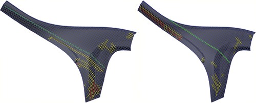
Preliminary analysis of composite parts is often performed based on idealized geometry and fiber orientations that meet loading conditions. However, without the understanding of fiber deviation, material knockdown factors are used to reduce the material’s mechanical properties. The result is an overbuilt composite part, which neither achieves the structural performance nor the desired mass reductions. Virtual visibility into the deviation and deformation of the material during the manufacturing process can minimize the risk of overdesigning parts. Often referred to as “simulation of manufacturing producibility,” this software-based capability is where the true fiber orientations can be known and then can be exchanged with those who do the analysis, as illustrated in Fig. 1, at left.
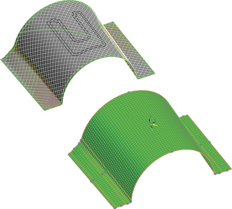
Taking a closer look, the detailed design process is started by importing the material lay-up from the analyzed finite element model and applying it to the CAD part. Next, the designer and manufacturing engineer, together, elect the best lay-up process and simulate it in the CAD environment, making the detailed part the basis for understanding the resulting material fiber orientations (Fig. 2). The resulting material properties and true fiber orientations are then passed back to the analyst’s pre-/post-solution, ensuring that local fiber orientations are known; thus, the analyst no longer is relying on theoretical orientations. The result is a part identified by correlating non-linear analysis with real part behavior, and can be designed within tight safety margins.
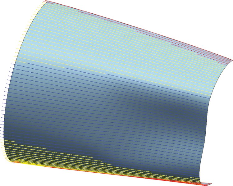
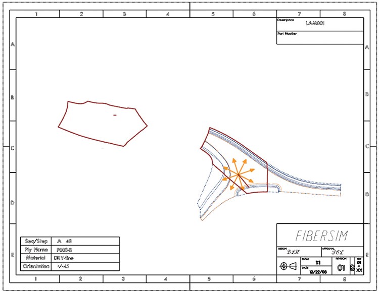
Delivering an optimized composite part requires that the fiber orientations of the production part fall within tolerance of an analyst’s desired part, which requires consistent manufacturing. Today, the majority of composite parts are still produced with manual lay-up processes, which innately introduce the risk of inconsistency. Although consistency increases when automated manufacturing processes are employed, additional constraints are introduced, which can affect fiber orientations, thus impacting designed performance. In the case of automated tape laying and fiber placement methods, for example, intended fiber orientation can be constrained by material radius-of-curvature limits. To ensure consistency, then, it is always necessary to compare the as-manufactured fiber orientations with the as-designed orientations (Fig. 3), and to communicate the simulated lay-up process used in part and flat pattern development (Fig. 4). Consistency can be achieved by simulating the manufacturing process in the context of the desired fiber orientations, ensuring delivery of an optimized composite part for performance and manufacturing.
To learn more, register for Siemens PLM Software’s Webinar on Thursday, Aug. 20, 2015 | attendee.gotowebinar.com/register/2967250198386487298
Related Content
Thermoset-thermoplastic joining, natural fibers enable sustainability-focused brake cover
Award-winning motorcycle brake disc cover showcases potential for KTM Technologies’ Conexus joining technology and flax fiber composites.
Read MoreASCEND program update: Designing next-gen, high-rate auto and aerospace composites
GKN Aerospace, McLaren Automotive and U.K.-based partners share goals and progress aiming at high-rate, Industry 4.0-enabled, sustainable materials and processes.
Read MoreJEC World 2022, Part 3: Emphasizing emerging markets, thermoplastics and carbon fiber
CW editor-in-chief Jeff Sloan identifies companies exhibiting at JEC World 2022 that are advancing both materials and technologies for the growing AAM, hydrogen, automotive and sustainability markets.
Read MoreJeep all-composite roof receivers achieve steel performance at low mass
Ultrashort carbon fiber/PPA replaces steel on rooftop brackets to hold Jeep soft tops, hardtops.
Read MoreRead Next
CW’s 2024 Top Shops survey offers new approach to benchmarking
Respondents that complete the survey by April 30, 2024, have the chance to be recognized as an honoree.
Read MoreComposites end markets: Energy (2024)
Composites are used widely in oil/gas, wind and other renewable energy applications. Despite market challenges, growth potential and innovation for composites continue.
Read MoreFrom the CW Archives: The tale of the thermoplastic cryotank
In 2006, guest columnist Bob Hartunian related the story of his efforts two decades prior, while at McDonnell Douglas, to develop a thermoplastic composite crytank for hydrogen storage. He learned a lot of lessons.
Read More






.jpg;maxWidth=300;quality=90)


