
Designing The Chanute Aerobatic Aircraft
Finite element modeling speeds development time and reduces uncertainty.


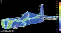
Source: Composites UnlimitedStep 5: Analysis of the entire fuselage shows highly stressed areas in red.
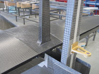
Intersection of the Chanute tail structure with the fuselage. The wide weave pattern of Toray's T700S 12K fabric is clearly visible.
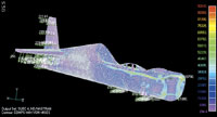
Source: Composites UnlimitedStep 7: The stress distribution in a model with more elements is similar to the coarse-mesh model, but shows finer detail.

Source: Composites UnlimitedStep 2: After the surfaces for all components are defined, a solid assembly model of the entire aircraft is created.
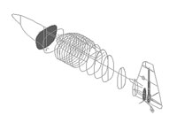
Source: Composites UnlimitedStep 1: Fuselage cross-sections will be joined with splines to define the aircraft lofting.
Composites Unlimited (Scappoose, Ore., U.S.A.) has manufactured aircraft components and assemblies since it was founded in 1994. Originally devoted to experimental aircraft, the company has expanded into certified aircraft, space, automotive, marine and industrial markets in recent years. But experimental aircraft still remain an important part of the business, and its customer services go beyond simple build-to-print work.
Composites Unlimited also designs composite tooling that keeps cost to a minimum. In some cases, tooling supplied by customers must be modified based on either manufacturing needs or changing design requirements. Further, the company provides engineering support for material selection, qualification and drafting for experimental and certified aircraft, and assists customers with non-structural systems such as fuel and flight control, as well. When Composites Unlimited contracted with kit-airplane supplier CADCOR (Bend, Ore., U.S.A.) to build the airframe for the Chanute, CADCOR's new two-seat, full-competition aerobatic aircraft, the company realized it could expedite the design process by performing the structural analysis in-house.


Optimizing design time
New aircraft design is an iterative process, with each design change requiring a new analysis. At any stage, this analysis might show that further design changes are required, which, in turn, would require another round of analysis. When design and analysis groups are located in different companies, the lead times between iterations can be very long. By performing much of the design and analysis work in-house, Composites Unlimited improves communication between the different groups and minimizes the time necessary for design change turnaround.
Structurally, the primary design requirement for the Chanute is a gross weight of 884 kg/1,950 lb and an aerobatic weight of 771 kg/1,700 lb. Gross weight refers to the maximum legal weight, including fuel, luggage, pilot and passenger, and other items. The gross weight determines how the plane performs and stalls during normal flight, establishing safe performance parameters for the average pilot. The aerobatic weight refers to the aircraft weight plus the minimum fuel, pilot and passenger weight for competition, and allows for higher performance parameters. Matt Giles, structural engineer at Composites Unlimited, set the target weight of the empty airframe at 544 kg/1,200 lb, which includes some margin for potential design changes.
Achieving maximum performance requires that the airframe be very stiff. With most airframes, stiffness becomes the primary design driver: if the material meets stiffness requirements, its strength will comfortably exceed that required to handle the stresses of aerobatic maneuvers. That means, however, that the airframe is over-designed for strength. For the Chanute, "the low aerobatic weight allows us to stress the frame as much as possible in competition," explains Giles, reducing the excess strength margin and improving performance.
Based on past experience, CADCOR had a good idea of what the Chanute should look like. The company provided Composites Unlimited with the general shape of the canopy, and cross-section templates of the fuselage at locations behind the pilot and behind the engine. Giles began his design work by importing these shapes into CAD software, selecting CADKEY (CADKEY Corp., Marlborough, Mass., U.S.A.), one of several popular CAD programs suitable for such applications. He then connected the shapes with splines (curves that connect points in space, calculated using a special mathematical algorithm to make sure they are smooth) to create a wireframe lofting of the entire fuselage. (A lofting is a full-scale model of the fuselage shape. The name comes from the factory lofts where full-size sailing ship patterns were made during the 19th century.)
To create a solid model of the aircraft, Giles imported the wireframe into SolidWorks (SolidWorks Corp., Concord, Mass., U.S.A.) to take advantage of the program's advanced 3-D capabilities. Both the fuselage and individual components were modeled. "The visualization is incredible," says Giles. "It allows me to see how components fit within a curved surface. Wireframes alone don't show part interferences." Each component is modeled as a separate, three-dimensional part, enabling Giles to move them around while trying to achieve the optimal position. SolidWorks can calculate mass properties for each part, so the overall weight and inertial properties of the aircraft can be determined as the design progresses.
CAD to finite element
The Chanute's design and performance parameters, along with preliminary drawings, were sent to an outside aerodynamicist. The aerodynamicist calculated lift requirements and aerodynamic loads (aeroloads), wing and tail airfoils and planforms, and the position of the tail with respect to the wing. Giles took these geometric details and incorporated them into the overall aircraft model. After roughing in some interior bulkheads as simple planes, the geometry was complete enough to begin detailed analysis.
Giles uses NE/Nastran for Windows (Noran Engineering, Los Alamitos, Calif., U.S.A.) for finite element analysis (FEA). NE/Nastran was developed for Windows systems and is fully compatible with other legacy Nastran programs. It includes a fully integrated pre- and post-processor for developing finite element models and reviewing the results.
Although the NE/Nastran modeler can directly read geometry created by SolidWorks' Parasolid engine, Giles decided to first translate the geometry into a neutral format, then import it into the modeler. Solid models are often too detailed for finite element analysis, and this approach allowed him to more easily restrict the model to the portions he needed. Giles used both STEP and IGES files (neutral formats developed by the CAD industry for data exchange between programs) for the conversion — depending on the particular component, sometimes one format provided a more accurate translation than the other. Two main FE models were created: one for the wing and one for the fuselage. Several smaller models were created to analyze individual control surfaces and other components.
Finite element modeling works by dividing a complex surface into smaller, simpler elements that can be modeled mathematically. Meshing, the process of overlaying elements onto the geometric surfaces is arguably the most difficult step in the modeling process. Element shapes should be as regular as possible (close to squares or triangles for shell elements) to improve accuracy. Smaller elements improve accuracy, but solution time or memory requirements can become prohibitive if the elements are too small. Element edges also must line up at geometric boundaries.
The NE/Nastran modeler includes an auto-mesher that can generate a mesh based on general parameters such as element size or density. It even has special features like size grading, that places small elements where needed for accuracy, but increases the element size where possible in order to minimize the total model size. Giles started by using the auto-mesher, but he found the mesh quality wasn't sufficient in areas where the geometry was complex. In the end, he used a custom mapping method that allowed him to manually specify the number of elements along a geometric edge. The initial mesh of the fuselage took about two weeks to create; the second iteration of the same model took less than one week. A low-fidelity model had about 7,000 elements, which was good for quick parametric studies, while the detailed model had about 30,000 elements. The wing model had between 5,000 and 9,000 elements. (The more common measure of model size is the total degrees of freedom, which is the number of possible translational and rotational motions possible at the model nodes. Giles didn't have those numbers available, but a rough estimate would be 6 to 12 times the number of elements. For more on FEA modeling, see "Accurate Simulation with Finite Element Modeling," HPC May 2002, p. 48.)
After meshing, geometric boundary conditions were applied to the model. These conditions fix the model in space to prevent rigid body translations or rotations from appearing in the analysis, and to represent how the different parts attach to each other. The wing model was pinned at the point the spar attaches to the fuselage; two other points, corresponding to actual joint fasteners, were fixed vertically to prevent rotations about the pinned joint. The fuselage model was constrained in a similar manner at the point it attaches to the wing.
Next come loads, which mathematically are treated as a type of boundary condition. The NE/Nastran modeler allows loads to be applied directly to nodes and elements, or to the underlying geometry. Giles applied most loads to the geometry, in part because the loads do not have to be redefined if the mesh is changed — the NE/Nastran modeler automatically translates the geometric loads into mesh-based loads. Loads must actually be planned for during the meshing process. To map the aerodynamic loads onto the structure, Giles divided the wing surface into regions. This forced element boundaries to lie along the edges of the regions and allowed him to apply loads to each region independently. Individual component weights were modeled as point loads; geometric features had to be created at each point to insure a node would be present for load application. Additional fuselage loads included tail loads, to twist the fuselage about the wing, and engine loads, to pull the fuselage against the wing. The weight of the fuselage itself was modeled as a distributed loading.
The final step was to assign physical and material properties to each element. Composites Unlimited had decided in advance to use Toray Composites America Inc.'s (Tacoma, Wash., U.S.A.) AGATE-qualified prepregs, including the 7781 fiberglass, the T700G 12K unidirectional carbon and the T700S 12K plain-weave fabric. Site equivalence testing was not needed, because the plane would not be certified, but the AGATE materials still provided high quality and high repeatability of properties.
Running the model
The wing model was initially run with a sandwich core layup consisting of two plies of ±45° carbon fabric for each facesheet and a 0.25-inch thick, 3.0 lb/ft3 Nomex honeycomb core from Hexcel Composites (Dublin, Calif., U.S.A.). The fuselage model started with the same sandwich laminate. Using the results of the analysis, the layups in different regions were adjusted to reduce the material used and hence reduce the weight of the aircraft. The target empty weight of 454 kg/1000 lb left only 181 kg to 227 kg/400 lb to 500 lb for the structural weight, so optimizing the laminates was critical to the success of the program. Giles used the initial layup for most of the wing and control surface structures, simply adjusting the core thickness in a few areas. After the first run, Giles added stiffeners made from unidirectional (UD) carbon to the fuselage. Later, he found that selectively reinforcing the fuselage with UD carbon in high stress areas (rather than adding stiffeners) provided the best performance and lowest weight.
Each model was run through the NE/Nastran solver to determine stresses, strains and deflections. The NE/Nastran modeler automatically translates the model into a Nastran input deck (command file), so it is not necessary for the analyst to know the specific Nastran terms for the finite element entities. For example, the analyst simply specifies shell elements instead of QUAD4s and laminate properties instead of PCOMPs.
Two types of analysis have been run to date: static and buckling (stability). The static analysis simply applies a constant load to the structure and solves the model in a single step. The 7,000-element model took between two and five minutes to run; the 30,000-element model took fewer than 10 minutes (run times can vary depending on the speed of the computer's processor, memory and hard drive). NE/Nastran calculated maximum strain and Tsai-Wu failure criteria from the stress and strain results, showing which areas of the structure needed to be reinforced. (Both failure criteria compare predicted ply stresses to strengths determined from unidirectional tests. The maximum stress criterion looks at each stress component individually to determine if a ply in the laminate fails. The Tsai-Wu criterion combines all stress components into a single equation, and includes terms to account for the interaction between individual stress components.) Giles also looked at interlaminar shear values in the areas with transitions between UD tape and fabric.
The buckling loads were determined using a linear eigenvalue analysis. This establishes a mathematical property (the eigenvalue) of the stiffness equations generated by the finite element program, which is related to the buckling and dynamic behavior of the structure. Eigenvalue analysis applies the loads in a single step, but the solution requires several iterations, which makes the overall solution time longer than a simple static analysis. The alternative is a nonlinear buckling analysis, which is more accurate but significantly slower than the eigenvalue analysis. Ultimately, buckling did not drive the design because the buckling loads were much higher than the flight loads.
At this time, the analysis has been completed and some prototype and testing parts have been made. Testing of material samples and smaller parts has begun. Testing of the larger structures is still in the planning stages, but Giles has high confidence in the design. While much of that confidence comes from experience with similar aircraft, finite element analysis can accurately predict structural behavior, removing much of the uncertainty from the structural design process.


.jpg;maxWidth=300;quality=90;format=webp)


Related Content

CFRTP enables better, greener smartphones
Carbon Mobile’s “monocoque” design eliminates separate case, cover and frame, better protects electronics and simplifies disassembly.
Read More
3D-printed CFRP tools for serial production of composite landing flaps
GKN Aerospace Munich and CEAD develop printed tooling with short and continuous fiber that reduces cost and increases sustainability for composites production.
Read More
Multi-material steel/composite leaf spring targets lightweight, high-volume applications
Rassini International was challenged by Ford Motor Co. to take weight out of the F-150 pickup truck. Rassini responded with a multi-material steel/composite hybrid leaf spring system that can be manufactured at high volumes.
Read More
Nine factors to consider when designing composites cure tooling
Gary Bond discusses the common pitfalls and compromises when designing good cure tooling and their holistic significance for a robust composite production process.
Read MoreRead Next

From the CW Archives: The tale of the thermoplastic cryotank
In 2006, guest columnist Bob Hartunian related the story of his efforts two decades prior, while at McDonnell Douglas, to develop a thermoplastic composite crytank for hydrogen storage. He learned a lot of lessons.
Read More
Composites end markets: Energy (2024)
Composites are used widely in oil/gas, wind and other renewable energy applications. Despite market challenges, growth potential and innovation for composites continue.
Read More
CW’s 2024 Top Shops survey offers new approach to benchmarking
Respondents that complete the survey by April 30, 2024, have the chance to be recognized as an honoree.
Read More