
Designing for high pressure: Large-diameter underground pipe
Careful analysis is needed to ensure success of buried composite piping for industrial applications.

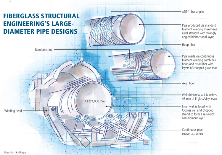
Fiberglass Structural Engineering's Large-Diameter Pipe Designs Illustration: Karl Reque
Large-diameter composite pipe intended for burial underground requires careful design to account for a range of load conditions that can impact performance. Source: FSE
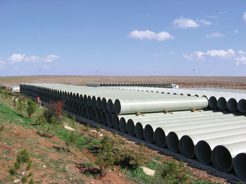
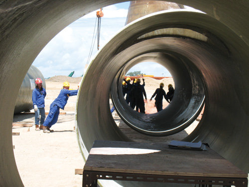
Completed large-diameter pipe (below) awaits installation at a project site. Source: FSE
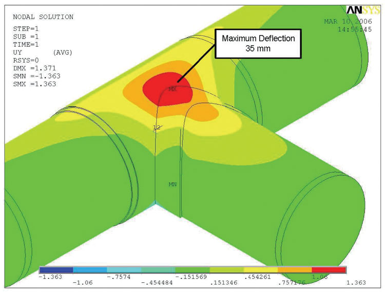
This screen shots show FE analysis of large-diameter pipe at a T-junction where two pipes will be joined using wet-laminating techniques (see also image below). Source: FSE
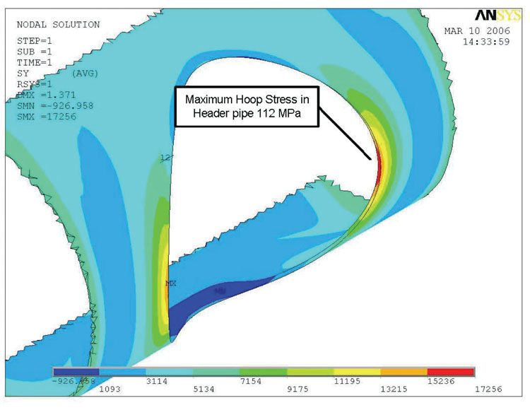
Another view of the large-diameter pipe T-junction shown above. Source: FSE
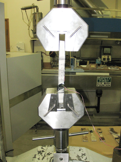
A sample section of large-diameter filament-wound pipe is tested in the laboratory for axial tensile properties. Source: FSE


Engineering Challenge:
For a yet-to-be-selected fabricator, design large-diameter, corrosion-resistant, filament-wound composite pipe with sufficient strength to resist burial and settlement loads as well as internal pressure and axial loads due to restrained contraction, without failing.
Design Solution:
Supplement industry pipe guidelines with calculations and finite element analysis that account for job-specific conditions, and then design ply schedules for both conventional and continuous filament winding processes that will yield comparable finished-pipe performance.


Underground pipe may seem mundane and unglamorous, but when those buried pipes are very large and specified in composite materials, design and fabrication is a big challenge. Although large-diameter composite pipes (48-inch/1,200-mm diameter and larger) have been specified as an alternative to thermoplastic, steel, iron and concrete pipe since the 1960s, a few spectacular failures during the 1980s forced the industry to take a hard look at its design process, notes Chris Renoud, professional engineer and CEO of Fiberglass Structural Engineering Inc. (FSE, Bellingham, Wash.). “Our corrosion industry has had a number of failures when compared to other composite applications,” he points out. “Underground composite piping is a growing application, great for many sectors, but good design is critical for success.”
FSE specializes in developing designs and specifications for project owners, who then procure pipes from third-party fabricators, Renoud explains. Fabrication techniques are typically standard helical filament winding or “continuous” winding (see “Making continuous composite pipe,” under "Editor's Picks," at right) but can include hand layup. The pipe sizes often exceed 10 ft/3m in diameter. The destinations for large pipe that will be buried below grade include power and chemical plants, oil refineries, desalinization projects and cooling-tower installations.
Underground pipe design process
A recent confidential project involved a design for about 5,000 linear ft/1,540m of 13-ft/4,000-mm diameter piping to convey seawater for a process cooling system at a Middle Eastern petrochemical plant. FSE’s principal engineer, Randy Rapoza, explains that composites were a given. They offered a favorable installed cost and neither coated steel pipe, cathodically protected steel pipe nor concrete pipe could match the 50-year maintenance-free service life of composites in a corrosive environment created by seawater, internally, and underground burial, externally. And, because fiberglass pipe has a smoother inside surface than other materials and accumulates no scale or deposits over time, it could permit a greater water flow over the life of the project.
The pipe was to be buried 7 ft/2.15m below grade and butt-and-strap joined. The joined pipe, therefore, would be restrained — that is, the pressure of the surrounding soil would lock the pipe in place with friction, limiting any movement without having to use thrust blocks (fixed structures that hold pipes in alignment). Rapoza stresses that the soil forces on the buried pipe are not trivial.
“You have to take into consideration the entire situation — the native soil conditions, the depth of water table, the temperature of the fluids that the piping will convey as well as ambient temperature during installation, traffic loads and so on. Loads due to burial, including those caused by differential soil settlement that causes the pipe to bend, far outweigh the typical forces on a pipe in an above-ground installation.”
The basis for the design was a widely used guide supplied by the American Water Works Assn. (AWWA), titled Fiberglass Pipe Design (a/k/a Manual M45). The manual provides equations that take into account the velocity and pressure of the conveyed fluid, head loss due to turbulent flow, water hammer, buckling pressure and surge pressure. But, explains Rapoza, that basic concept was supplemented with other calculations to cover a host of site-specific design conditions that can’t be addressed by the M45 guide, including soil type and density, depth of cover and allowable vehicular traffic load. Sometimes FSE also must consider severe live loads from cranes and construction equipment in the calculations, which the backfill must support, as well as average and maximum service temperatures, shape factor (or deflection due to bending stress from soil loads) and more. “It’s a fairly extensive calculation process,” he reports. Ultimately, this process led to an interim solution for the pipe wall thickness and stiffness that was necessary to handle water pressure loads and to prevent any buckling or excessive deflection and stress under the project burial and operating conditions.
The designers then employed finite element analysis (FEA) methods for detailed stress analysis, combining hoop and axial loads, to verify the pipe design. FSE uses ANSYS Inc. (Canonsburg, Pa.) for FE modeling software. Depending on the pipe’s modeled performance at the calculated wall thickness under project conditions, Rapoza says designers might have to go back through the calculations to tweak the design, optimizing thickness and laminate design or increasing axial stiffness to meet the performance goals. “The analysis often requires several iterations,” he says.
The final calculated wall thickness for the 13-ft/4m diameter pipe was a considerable 1.8 inches/46 mm for pipe sections that were 39 ft/12m in length. The design pressure was 10 bar (gauge)/145 psi (the operating pressure would be 8 bar/116 psi), and the design temperature was 150°F/66°C, although the operating temperatures were expected to be around 115°F/46°C.
Key to the analysis and design of the glass reinforcement schedule was “restrained thermal contraction and restrained contraction from the Poisson effect of internal pressure,” says Renoud, who points out that these often-overlooked conditions were the cause of many early composite pipe failures. When a pipe is buried in hot ambient conditions and then operated (or shut down) at a lower temperature, he explains, it wants to contract, but it is axially restrained by the soil and can’t move. Similarly, when the pipe tends to expand in the hoop direction due to pressure, it tries to contract in the axial direction but cannot, resulting in significant axial forces. Composite pipe, unlike steel or concrete, tends to be weakest in the axial direction, says Rapoza. “The tensile stress can literally tear the pipe apart.” To account for these restrained loads, he explains, sufficient axial fibers were specified in the design to ensure adequate axial tensile strength in the pipe wall. Additionally, the installation instructions specify the maximum temperature at the time of burial to control the differential between the installation temperature and the pipe’s minimum use temperature (60°F/15.5°C, in this case).
Composites meet conditions
Next, designers specified E-glass, and a vinyl ester from Ashland Performance Materials (Dublin, Ohio), with a fiber-to-resin ratio of about 60 percent by weight. FSE’s senior project manager Steve Gaber says vinyl ester offers better corrosion resistance and is “more flexible and provides better strain properties than a polyester.”
FSE then developed the laminate architecture. Rapoza explains that because the fabricator had not yet been chosen, it was unknown whether standard helical winding or continuous winding methods would be used. “We actually developed one specification covering both methods, each about equal in thickness and with ... materials adjusted so that pipe performance would be the same, regardless.”
For standard filament winding, in which a fixed male mandrel equal in length to each pipe length is rotated by a headstock and tailstock, an initial C-glass surfacing veil (0.01 inch/0.25 mm in thickness) would enable a resin-rich inner surface, followed by one ply of chopped strand mat to complete a chemical-resistant and flexible pressure containment barrier. Then, 35 cycles of E-glass fiber would be wound (from the head to the tail and back) at a ±55° winding angle (with the pipe’s horizontal axis at 0°) to maximize axial strength, says Rapoza.
For pipe made in a continuous winding process, the reinforcement spec was considerably different. The same C-glass veil was followed by a layer of random chopped glass mat, then more than 100 plies of alternating hoop-wound glass fibers (90° winding angle) and chopped glass, with multiple interspersed plies of unidirectional (0°) tapes. The hoop fiber contains the internal pressure loads and provides the stiffness necessary to resist deflection or “ovaling” due to burial loads. The uni tapes, applied by hand or machine wound, add axial strength to resist the previously noted restrained thermal and Poisson loads and other axial loads.
To ensure that pipe lengths would be consistent with the specifications, FSE developed testing and quality-assurance guidelines for the fabricator. Samples would be taken periodically and tested for thickness, glass content (ASTM D2584), correct ply sequence, hoop tensile strength, hoop modulus of elasticity, axial tensile strength and axial modulus of elasticity and stiffness (per guidance provided in AWWA C950). A key FSE specification concerned the joining of pipes during installation. Rapoza and Gaber emphasize that FSE’s preferred method for this project type is a wet-laminated butt joint, using glass woven roving and chopped strand mat. “If correctly completed, the joint will be stronger than the pipe itself,” Gaber claims. FSE offers its clients the option of onsite QA surveillance of joining operations and can recommend contractors with experience in both joinery and repairs.
To ensure a consistent, predictable backfill, FSE specified a clean, well-graded soil and backfill with a density of no more than 120 lb/ft3, says Rapoza. Although some settlement is inevitable, he recommends that engineers design for no more than 20 mm/0.8 inch of settlement in each 20m/65 ft of pipe length.
Concludes Renoud, “A lot of these design steps are often overlooked by project engineers and designers. Everyone in the industry will benefit by recognizing that these large structures must be carefully engineered.”


.jpg;maxWidth=300;quality=90;format=webp)


Related Content

Protecting EV motors more efficiently
Motors for electric vehicles are expected to benefit from Trelleborg’s thermoplastic composite rotor sleeve design, which advances materials and processes to produce a lightweight, energy-efficient component.
Read More
Drawing design cues from nature: Designing for biomimetic composites, Part 1
Biomimicry is an interdisciplinary methodology that can inform composites design and manufacturing via use of more effective and sustainable materials, structural fabrication and technological practices.
Read More
The next evolution in AFP
Automated fiber placement develops into more compact, flexible, modular and digitized systems with multi-material and process capabilities.
Read More
Optimizing AFP for complex-cored CFRP fuselage
Automated process cuts emissions, waste and cost for lightweight RACER helicopter side shells.
Read MoreRead Next

CW’s 2024 Top Shops survey offers new approach to benchmarking
Respondents that complete the survey by April 30, 2024, have the chance to be recognized as an honoree.
Read More
Composites end markets: Energy (2024)
Composites are used widely in oil/gas, wind and other renewable energy applications. Despite market challenges, growth potential and innovation for composites continue.
Read More