
Composites take the hit in U.S. Navy patrol boat
New carbon/Kevlar composite hull and deck provide impact-absorbing solution to crew injury problems caused by severe vertical acceleration of previous high-speed, all-metal patrol boat.


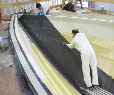
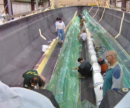
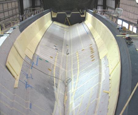
Step 3: The outer layer of hull laminate fabrics were installed: a thin veil first, then one ply of Kevlar, followed by first carbon layer shown here.
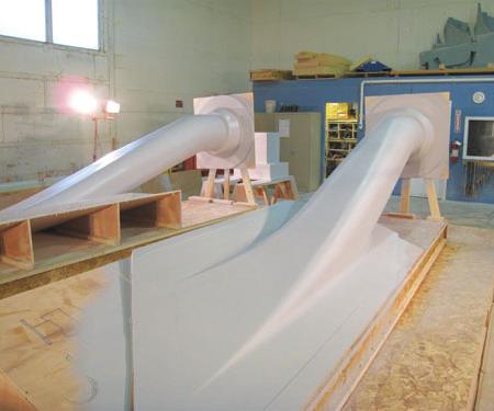
Janseneering used a 5-axis CNC mill to cut the complex foam molds used to fabricate MAKO's carbon fiber composite waterjet tunnels. Source: Janseneering
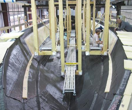
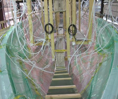
Step 4: After laying in Kevlar/carbon outer skin reinforcements, the pre-fit Corecell foam was reinstalled using this suspended scaffolding system.
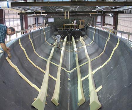
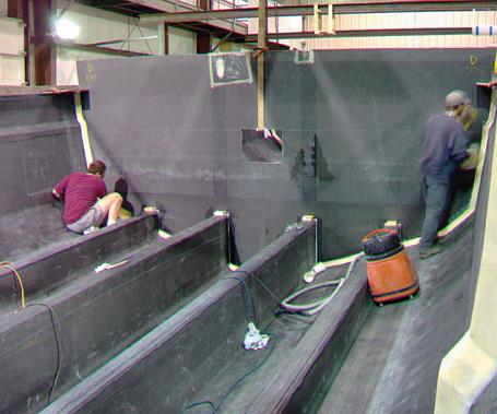
Step 6: Laser projection devices were used to locate the CNC-cut longitudinal core forms. Transverse stringer core forms were then added, via an interlocking system.
Step 7: Longitudinal core forms were finished with carbon fiber reinforcements, bagged and infused.
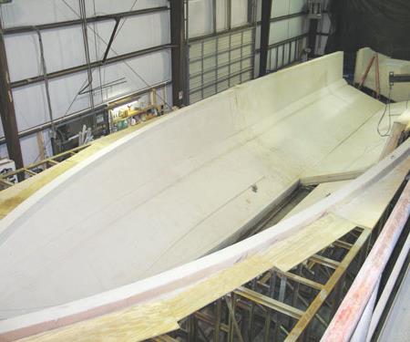
Step 1: The polyurethane foam and fiberglass hull mold was cut into five pieces for transport to Maine, then reassembled, faired smooth, coated with fiberglass and Duratec. Source: Maine Marine Manufacturing
Step 12a
Step 11a.
Step 2: Corecell core pieces were cut and prefit into the mold, then labeled and removed for later installation.
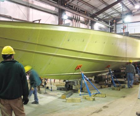
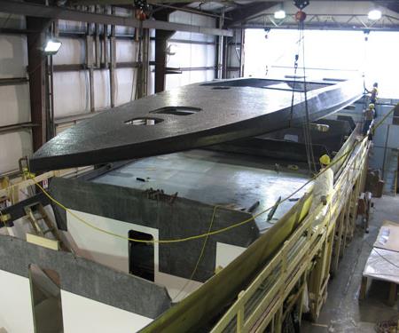
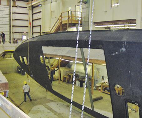
Step 10: Once all internal structure was installed, the hull was removed form the mold and readied for postcuring.
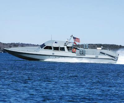
The all-composite MAKO patrol boat (pictured) is 50 percent stronger and slightly lighter than the all-aluminum Mark V now in use by U.S. Navy SEALs. It was launched in January 2008 and is currently being tested by the Navy alongside the Mark V for comparison. Source: Maine Marine Manufacturing
Step 9: Pre-infused bulkheads were fitted- like this one, to the transverse cleat- and then tabbed to the hull using carbon tape and epoxy.
Step 12: The deck was built upside down on a male mold, infused, post- cured and then rolled over prior to being installed on the hull (inset).
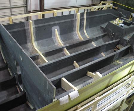
Step 8: After longitudinals were infused, transverse stringer cores were finished with carbon reinforcements and infused.
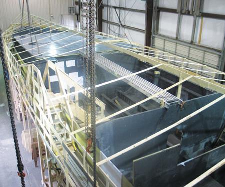
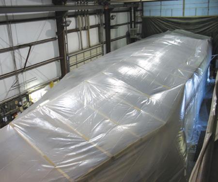
Step 11: After demolding, the hull/structural grid assembly was sealed in a tent oven (framework shown in large photo) and postcured for 10 hours.
Step 5: Infusion began at the hull bottom and the flow front worked up uniformly in seven vertical feed zones per hull side, taking about 1 hour, 45 minutes.
The Mark V Special Operations Craft (SOC) is the U.S. Navy SEALs' high-speed, medium-range insertion and extraction vehicle, also used for limited coastal interdiction. The 82-ft/25m-long, 57-ton patrol boat was designed to carry 16 fully equipped Navy SEALs through rough seas at speeds of greater than 50 knots to destinations as far as 500 miles/805 km from their base, on missions lasting as long as 12 hours. Originally built from aluminum by Halter Marine (Gulfport, Miss.), the Mark V was developed fairly quickly, with first delivery in September 1995, only 18 months after the initial contract award. By 1999, the entire fleet of 20 Mark V SOCs had been delivered at a cost of $3.7 million apiece. Twelve were assigned to Naval Special Warfare Group THREE (NSWG-3) in Coronado, Calif., and eight others went to NSWG-4 in Little Creek, Va.
In action, the boats proved to be very tough, but they also were tough on occupants. According to Lt. Damon Shearer, senior medical officer of the NSWG-4, forces upward of 20 times that of gravity (20 Gs) have been produced by the aluminum Mark V as it slammed against large waves. (Note that fighter pilots are subjected to forces up to 10 Gs). Accelerometers mounted on Mark Vs showed that crews were being subjected to 4- to 5-G impacts one to two times per minute during operations at cruising speed (35 knots) in 3-ft to 4-ft (0.91m to 1.22m) waves. This subjected all onboard personnel to extreme vertical accelerations, producing a wide range of injuries (e.g., sprained ankles, fractured molars, whiplash and spinal injuries) and leaving the uninjured exhausted and compromised before the mission's real work began.
By 2003, the Navy had determined that at least part of the problem was inherent in the design and construction of the Mark V. Unfortunately, that same design also achieves key performance factors: Its deep-V (24° of dead rise from midship aft) planing hull, made from 5086 aluminum, is designed such that when the boat reaches a certain velocity, called the planing speed, the front part of the hull rides up out of the water. With a relatively small surface area in contact with the water, the planing hull is subject to less drag, enabling the boat to travel at higher speeds with greater maneuverability. Also, the Mark V's angular design and low silhouette reduces its radar signature, making it harder to see and detect, which improves survivability. The problem the Navy faced, therefore, was how to redesign the SEALs' workhorse vessel to ensure crew safety without losing the operational advantages of the existing design.
Tapping two centuries of boatbuilding experience
About that same time, Tim Hodgdon formed Maine Marine Manufacturing LLC of Portland to parlay his family's nearly 200 years of boatbuilding technology and experience into military marine and other advanced composites projects. The Hodgdon family has been building boats in East Boothbay, Maine, since 1816. Father and son, George I. Hodgdon Sr. and Jr., built wooden minesweepers and transports during World War II, earning a banner from the Navy with the insignia "E for Excellence." Grandson Tim had taken the helm as president of Hodgdon Yachts, overseeing the launch of a number of large sailing vessels and motoryachts, often combining wood and carbon/epoxy composites to meet challenging customer requirements for luxury and performance. Aware of the Navy's need for a Mark V redesign, he saw it as an ideal first project for Maine Marine Manufacturing and approached the University of Maine's Advanced Engineered Wood Composites (AEWC) Center (Orono, Maine) to form a design team. The AEWC was a strategic choice because it had been working with the Office of Naval Research (ONR) in Arlington, Va., for several years. (AEWC's current boatbuilding projects are worth more than $1 million USD per year.) The team worked with Maine's congressional delegates to organize a four-year technology demonstrator project, funded by the ONR, to develop a completely new, all-composite design and build a prototype for extensive testing by the Navy.
Absorbing impact with all-new composite design
Maine Marine Manufacturing brought in renowned naval architectural firm Donald L. Blount & Associates Inc. (DLBA, Chesapeake, Va.). According DLBA's technical director Dean Schleicher, the company's focus was not on how to absorb slamming loads but instead on how to avoid generating 20-G loads in the first place. It was clear that the new vessel, named MAKO, after the shark that prowls the waters near the Gulf of Maine, would need a completely new hull design.
During the Navy's Coastal Patrol Interdiction Craft (CPIC) project in the 1970s, DLBA had gained experience analyzing seakeeping criteria for high-speed patrol boats. (Seakeeping is the ability of a vessel to navigate safely and operate effectively at sea, even in high waves, for prolonged periods.) The company also had done seakeeping research on the Mark V for the Navy and had worked on a generic 100-knot patrol boat project during 2000-2004. The knowledge acquired on these projects led DLBA to propose for the MAKO a double-chined hull form (like that of the CPIC), which significantly reduces slamming versus a single-chine hull by offering a narrower hull bottom. The chine is the creased mating line where the side and bottom of a V-bottomed boat meet. As can be seen in Step 10 (see process step photos, at left), there are two chines on each side of the hull between MAKO's in-water hull bottom and above-water hull sides. The Mark V hull has only one chine on each side. Schleicher explains: "At slow speeds, this hull form presents the full beam of the boat (17.5 ft/5.3m), providing stability; but when the boat is running at planing speed, the 45° panel between the two chines exposes a narrower beam, minimizing the area for slamming." The new hull was designed with an overall length of 82 ft/25m.
The new hull design was the first aspect of what would be a multifaceted impact reduction system. The next question that confronted the team was, Can composites reduce the vertical acceleration problem? Maine Marine Manufacturing had enlisted the services of Eric Greene Associates (Annapolis, Md.) early on to perform preliminary composites structural design and laminate trade-off studies, looking at composite panels that would be strong enough but less stiff to provide shock mitigation. However, the team needed a test method that would replicate the slamming forces on the boat's hull and enable designers to evaluate which laminates and construction methods actually performed best. This was AEWC's part of the program, in addition to providing overall technical management and the interface with ONR. AEWC began with a test method originally developed by the Florida Institute of Technology (Melbourne, Fla.) in which a large flat panel is subjected to loads using a water bladder to simulate wave slamming. AEWC used realistically sized 5-ft by 10-ft (1.5m by 3.0m) panels for testing. Internal stiffeners were attached to the panels to more accurately simulate the deflection and stress conditions experienced in service.
The panels were held in place by a wooden box built 0.5 inch/127 mm wider than the panels and lined with plastic to contain leaks. AEWC then built a steel impact tower, which enables a 200-lb/91-kg weight to be dropped from heights of 5, 10, 15 and 20 ft (1.52, 3.05, 4.57 and 6.10m); it also built a rectangular steel loading frame that distributes the impact load to the edges of the panel. During testing, panels were bolted to the loading frame and placed on top of the water bladder. The panel-frame assembly was then bolted to the impact tower. When the weight was dropped onto the loading frame, the impact drove the test panel into the water bladder, simulating the action of a boat hull slamming into a wave. The panel and frame were instrumented with 16 accelerometers capable of measuring forces up to 5,000 Gs. The impact absorbed by the test panels was measured as the difference between the acceleration recorded on the panel and that recorded on the frame. The panel with the lowest recorded acceleration was the composite laminate determined to absorb the most impact.
5086 aluminum and four composite material systems were evaluated using the AEWC impact test method: (1) a solid laminate of E-glass/vinyl ester resin, (2) a solid laminate of carbon fiber/epoxy, (3) a sandwich construction with E-glass/vinyl ester skins and styrene acrylonitrile (SAN) foam core, and (4) a sandwich construction with hybrid carbon/aramid fiber-reinforced epoxy skins and SAN foam core.
All of the composite test panels were made by Maine Marine Manufacturing via a generic closed mold VARTM process that has been used for years by the Navy due to the high quality of the resulting laminate. Already committed to the use of a closed-mold infusion process, Maine Marine Manufacturing was comfortable with VARTM.
The internal stiffeners — foam-cored hat stiffeners — also were infused, using PRISMA beam preforms supplied by Compsys Inc. (Melbourne, Fla.). The stiffener preforms were secondarily infused over the previously VARTM'd composite panels. Longitudinal string-ers were spaced on 18-inch/460-mm centers for the quasi-isotropic single-skin panels and on 27-inch/670-mm centers for the cored constructions. Transverse stringers were located 54 inches/1,400 mm apart for both single-skin and sandwich panels.
All of the composite test panels showed lower acceleration measurements from the same height than did the 5086 aluminum panels, with the carbon/aramid reinforced epoxy sandwich absorbing the most impact load among the four composite systems evaluated. The team input the latter's test results into structural analysis and design software to develop an overall hull and internal support structure that would match the stiffness of the Mark V's hull, yet maintain the impact absorption capability demonstrated in testing. Other factors that had to be considered were weight, manufacturability and cost. AEWC used both Vectorlam, a laminate design program developed by Vectorply Corp. (Phenix City, Ala.), and its own internally developed laminate analysis software. To help meet project deadlines, Maine Marine Manufacturing also contracted with Applied Thermal Sciences (ATS, Sanford, Maine) to complete finite element analysis (FEA) and structural design, primarily on the MAKO's crew deck.
Maine Marine Manufacturing's in-house design group developed a laminate schedule to meet FEA-identified loads and stress areas, featuring a combination of fiber orientations, including double-bias and unidirec-tional carbon reinforcements. Woven aramid reinforcement (Kevlar brand, manufactured by DuPont Advanced Fiber Systems, Wilmington, Del.) was added in the outer skin to boost impact resistance and build thickness. The SAN foam core — Corecell, manufactured by Gurit NA (Magog, Quebec, Canada) — varied in thickness from 1.5 inches to 2 inches (38 mm to 51mm), depending on its location in the hull: The transom, forward hull and hull bottom required greater thickness, as did areas where the hull panel area between stiffeners would be greater, to keep deflection in check.
Building a virtual and physical prototype
While AEWC worked on developing a test method, completing all of the impact testing and then applying those results to the computer-aided design process, Maine Marine Manufacturing developed the materials candidates for impact testing and began infusing test panels as well as experimenting with different infusion setups and process variables. The company tested a wide range of epoxy resins, and though all had comparable properties, they selected Gurit's epoxy infusion resin because it gave the best balance of properties and manufacturability. Andre Cocquyt, president of GRPguru (Brunswick, Maine), was brought in to assist with finalizing process parameters and process control. By summer 2006, the MAKO development project was ready to begin prototype fabrication.
Chesapeake, Va.-based DLBA Ro-botics Ltd., a separate and independent provider of CNC machining services for large structures, fabricated the female mold for MAKO's hull — a temporary tool with a capacity of 5 to 10 parts, CNC-cut from polyurethane foam. To help make the mold vacuum tight, DLBA Robotics used Polyfair T27, a sprayable, machinable resin specially formulated for CNC machining by ATC Formulated Polymers Inc. (Burlington, Ontario, Canada). The mold was cut into five pieces for transport to Maine. There, it was reassembled, faired smooth, coated with fiberglass and the Duratec polyester tool-coating system formulated by Hawkeye Industries Inc. (Marietta, Ga.) and then checked for vacuum integrity. Maine Marine Manufacturing built the tooling for the MAKO's deck and canopy in-house, using glass/epoxy-covered foam and plywood.
Prior to layup of the hull's outer skin, Corecell foam core was cut and prefit into the mold. When all the core pieces were in place, they were labeled and removed for reinsertion later. For the outer skin layup, a thin (1.5 oz) fiberglass veil was applied first to enhance cosmetics, followed by one ply of woven Kevlar and then the carbon reinforcements. Next, the prefit, precut Corecell foam core and carbon inner skin materials were applied. A suspended scaffolding system enabled workers to install core and reinforcements without damaging or skewing the materials.
The infusion process was designed to begin at the bottom of the hull using seven vertical zones per hull side. A resin feed line was established for each zone, and was, in turn, connected to interlaminate flow media. Zones were infused simultaneously, with the resin front working its way uniformly to the top of the hull. Wetout was complete in 1 hour, 45 minutes.
When the hull laminate was solid, bulkheads and stringers were added while the hull continued to cure in the mold. The preforms used in the composite test panel stiffeners were not used in the actual hull fabrication. Instead, hull stiffeners were cored with Corecell foam in high-load areas and with 2-lb polyurethane foam where structural properties were not required. The Corecell was CNC-cut by David Jansen of Janseneering Inc. (Topsham, Maine) using a 5-axis CNC profiling mill. A 3D CAD file was required because the stringers were designed to follow the shape of the hull, and actually twisted and changed height as they progressed from the stern of the boat forward. Jansen fabricated the stringer cores to interlock and snap together like puzzle pieces, and to index where each stringer section fits into the next section.
Similar to those for the test panels, the prototype's stiffeners were secondarily infused; doing so enabled a simpler and more foolproof yet high-quality process. Laser projection devices were used to shoot the location lines for the stringers onto the hull surface, and then the puzzle-piece system enabled the remaining grid components to be located. Spray adhesive was used to adhere the foam to the hull, and then dry carbon fabric was laid over the top. The longitudinals were infused first, one at a time, followed by the transverse stringers. Then pre-infused carbon/foam-cored bulkheads were installed. As was the case with the hull laminate, the stiffener grid was allowed to fully cure before the entire assembly was demolded. A Navy requirement for VARTM'd structures, this delay reportedly ensures a solid assembly and prevents twisting and warpage.
After demolding, the hull was instrumented with thermocouples hardwired to a remote readout and sealed in a temporary tent for postcure at 140°F/60°C for 10 hours. (The hull could not be postcured in its mold because the foam-cored mold would insulate the hull's outer skin and prevent it from exposure to the necessary elevated temperature.) When fabrication of MAKO's hull was complete, its deck and canopy were infused, postcured and attached.
The program then entered its next phase in which the vessel was outfitted with two MTU 2000 series 2,400-hp diesel engines (made by MTU in Friedrichshafen, Germany) and twin water jets made by Kamewa (Kristinehamn, Sweden), a subsidiary of Rolls-Royce (Derby, England). Systems installation followed, including steering, piping, electrical and interior structure. Maine Marine Manufacturing and Hodgdon Yachts launched the MAKO on Jan. 11, 2008. The boat was then put through boatbuilder and customer acceptance trials off Maine, and it was finally delivered to NSWG-4 in Norfolk, Va., in early March 2008. According to Maine Marine Manufacturing president and CEO, David Packhem Jr., team members and the Navy are pleased. "We achieved our goals in designing and building this boat. It is actually 50 percent stronger and slightly lighter than its aluminum predecessor, and we expect that Navy testing will confirm that we've been able to reduce transmission of slamming loads." MAKO has completed the Navy's calm-water testing and is now undergoing rough-water testing. Other instrumented testing should be concluded this summer, including running the Mark V and MAKO side by side for comparison.
Meanwhile, Maine Marine Manufacturing is completing additional work to further refine the MAKO design — Packhem believes even more weight can be cut while maintaining the MAKO's performance. In addition, the company is already looking at a variant that would maintain the original speed and range but include interior crew accommodations that would permit the Navy to extend mission deployments. Other projects under consideration include 43-ft/13.1m and 140-ft/42.7m vessels with hull forms and carbon-aramid/epoxy composite technology similar to the MAKO.


.jpg;maxWidth=300;quality=90;format=webp)


Related Content

CityAirbus NextGen to be developed for future medical missions in Norway
Airbus and the Norwegian Air Ambulance Foundation partner to measure the added value of eVTOL aircraft for medical use cases across Norway.
Read More
The state of recycled carbon fiber
As the need for carbon fiber rises, can recycling fill the gap?
Read More
Materials & Processes: Composites fibers and resins
Compared to legacy materials like steel, aluminum, iron and titanium, composites are still coming of age, and only just now are being better understood by design and manufacturing engineers. However, composites’ physical properties — combined with unbeatable light weight — make them undeniably attractive.
Read More
Cevotec’s fiber patch placement is part of digital process chain for automated composite prosthetics
Multiple partners work to develop automated data collection, composite laminate generation for customized medical applications using FPP technology in German-funded Patch2Patient project.
Read MoreRead Next

From the CW Archives: The tale of the thermoplastic cryotank
In 2006, guest columnist Bob Hartunian related the story of his efforts two decades prior, while at McDonnell Douglas, to develop a thermoplastic composite crytank for hydrogen storage. He learned a lot of lessons.
Read More
CW’s 2024 Top Shops survey offers new approach to benchmarking
Respondents that complete the survey by April 30, 2024, have the chance to be recognized as an honoree.
Read More
Composites end markets: Energy (2024)
Composites are used widely in oil/gas, wind and other renewable energy applications. Despite market challenges, growth potential and innovation for composites continue.
Read More