
Complex Composites Lighten Nato Copter
Dutch consortium develops advanced composite critical landing gear that meets NH90 helicopter performance requirements.


Source: NLRA finite element analysis model of the highly loaded center section of the trailing arm.
Source: NLRCarbon fiber/epoxy torque link, produced via RTM.
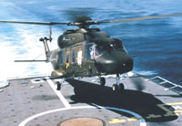
Source: NH IndustriesNavy version of the composites-intensive NATO NH90, making a deck landing.
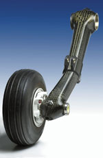
Source: NLRCompleted trailing arm assembly.
The application of carbon fiber composites to the wings and fuselage of a newly designed aircraft is now standard practice. One area of aircraft design that continues to elude the composites community, however, is the landing gear. As primary structural elements with concentrated loads, conservative design practice has traditionally dictated metal in these components. This may change if a team of Dutch companies and scientists is successful in its quest to design and fabricate lightweight, durable composite landing gear for helicopters and fixed wing aircraft.
SP aerospace and vehicle systems (Geldrop, The Netherlands) is under contract for the development, qualification and production of a retractable, crash-worthy landing gear for the NATO NH90 helicopter, in both Army (TTH, or Tactical Transport Helicopter) and Navy (NFH, or NATO Frigate Helicopter) versions. A joint development of Eurocopter (France and Germany), Agusta (Italy) and Fokker (The Netherlands), this 10-ton-class helicopter will be used for a wide variety of tasks, such as troop transport, cargo transport and anti-submarine operations. Composites are widely used throughout the helicopter, such as in the airframe, stabilizers, and the rotor blades. Development prototypes of the helicopter have been flying since 1995 and the first serial production delivery is scheduled for 2004. The NATO Helicopter Management Agency (NAHEMA), consisting of France, Germany, Italy, The Netherlands and Portugal, has ordered 253 helicopters with an option for 124 more. The Nordic countries (Sweden, Finland and Norway) have ordered 52 units, with an option for an additional 17.


The landing gear is currently designed in metal. In the mid-1990s, SP aerospace, in conjunction with the Structures and Materials Division of the Netherlands National Aerospace Laboratory, NLR (Amsterdam, The Netherlands) began exploring the use of advanced composites, convinced that composites technology had matured to a point where a landing gear application was practical, according to René Hekerman, engineering manager for SP aerospace.
In 1996, the team initiated a technology development project to design, build and validate carbon fiber composite torque links and a trailing arm assembly based on NH90 landing gear specifications. SP aerospace is the lead company for the project, responsible for concept design component specifications, integration of components into the landing gear, and component testing and qualification. NLR is handling the conceptual design for the composite elements, development of design allowables, development and manufacture of the RTM production molds and the composite parts, and subsequent testing of the subcomponents. Two additional partners provide specific expertise: Eurocarbon (Sittard, The Netherlands) has responsibility for the development of a fully automated overbraiding technique for the fabrication of cost-effective preforms for the composite trailing arms, while MSC.Software Benelux BV (Gouda, The Netherlands) provides the finite element analysis (FEA) of the mechanical strength of the composite structures.
Funded by the Dutch Government and the partners themselves, the program is split into two phases: technology development and validation. The torque link was developed from 1996 to 1999. This relatively simple component was used as a demonstrator in order to bring the design, analysis and RTM capabilities to a higher level. This enabled development of the trailing arm's very complex shape, which was had its beginnings in 1998 and was largely completed in 2002.
Complex parts take advantage of design and analysis software
For design purposes, loads were derived from helicopter landing and ground and ship deck handling cases. The specified crash landing speed of 11m/36 ft per second results in a combination of severe bending and torsion loads on the trailing arm. In order to guarantee sufficient damage tolerance, maximum allowable design strain levels were determined experimentally. Since the landing gear components have concentrated load introductions, design strain levels for pin-loaded holes (the openings into which pivot pins are inserted when landing gear components are joined together) were determined by testing sub-components.
Other factors considered during the design process were affordability and manufacturability, impact scenarios, maximum operating temperatures, chemical resistance to hydraulic fluids, and galvanic corrosion between the bushings and the composite components, explains Bert Thuis, NLR's group manager, development and evaluation.
The parts were designed at SP aerospace using Pro/Engineer software (PTC, Needham, Mass., U.S.A.), while NLR used CATIA (IBM PLM, Dallas, Texas, U.S.A.) for the tooling design. From the different finite element codes that are supplied by MSC.Software, the team opted to use MSC.Marc for this project, notes Maarten Oudendijk, MSC.Software's technical consultant. This decision was based on the non-linear capabilities of the program in the areas of material behavior (i.e., material failure) and geometry, e.g., automated 3-D contact between the structure's different modeled components.
MSC.Marc has the capacity to analyze layered composite materials, with different fiber orientations in each layer. Some sections of the trailing arm have up to 50 layers of reinforcement, which greatly complicates the analysis. To reduce the number of elements and the number of degrees of freedom in the system, routines have been developed to treat the layered composite as a homogenized, but still orthotropic, material. To derive these homogenized material properties, numerical tests are performed on a unit cell — the cube of material that makes up a "finite element" within the layered material. The results from these numerical experiments are then converted to averaged properties. A damage model is implemented, which simulates a fracture in one area of the part and determines whether or not the resulting loads would propagate that damage to other areas, i.e., exceed their limit loads and cause delamination. This also has been applied to the homogenized material, by calculating the damage throughout the layered material. The analysis portion of the project was divided into three sub-projects, involving the analyses of the torque-link, the mid-section of the trailing arm and the full-scale trailing arm.
Preforming and RTM prove manufacturing capability
Resin transfer molding (RTM) was selected as the fabrication method for both components because the shapes of landing gear components often are complex and therefore very difficult or even impossible to make using traditional prepreg/autoclave technologies, NLR's Thuis emphasizes.
Preforms for the torque links and the trailing arm's center lugs are hand layed, using woven carbon fiber fabrics supplied by C. Cramer & Co. (Heek-Nienborg, Germany). The composite trailing arm preform is made as follows. First, two cured carbon/epoxy tubes made with roll-wrapped prepreg are bonded to a core made of a low melting metallic alloy. This assembly is then triaxially overbraided by Eurocarbon using T300-12K carbon fiber from SOFICAR, a division of Toray Carbon Fibers (Abidos, France). According to Eurocarbon managing director Arnold Voskamp, approximately 60 percent of the fibers are placed in the ±45° orientation, and 40 percent in the longitudinal direction. By design, final wall thickness varies from 15 to 30 mm/0.6 to 1.2 inches at over 50 percent fiber volume. The braider used is a computer-controlled 96 carrier machine, and can handle parts as large as 600 mm/23.6 inches in diameter and as much as 7 m/23 ft long. Voskamp says Eurocarbon recently installed a 216 carrier machine for even larger preforms.
Before loading the RTM molds, the trailing arm preform and lug preform are assembled. The combined preform is then positioned within an aluminum tool. After closure, the mold is heated and a specially formulated epoxy resin from Cytec Engineered Materials (Tempe, Ariz., U.S.A.) is injected under pressure over a period of several hours. In order to determine the optimal injection strategy, extensive flow simulations were carried out at NLR. During the RTM cycle, a data acquisition system records the most important parameters, such as resin temperature, mold temperature, resin flow and injection pressure, in order to demonstrate reproducibility of the RTM process, Thuis explains. After a two-to-three hour cure in the mold, the composite trailing arm is removed and positioned in an oven for a free standing post-cure, during which the alloy core melts out. The alloy can be reused in the next trailing arm.
The only machining required is cutting the ends of the trailing arm, milling the edges of the lugs and drilling the holes in the lugs. The upper and lower torque links are approximately 175 mm/7 inches long and weigh 0.12 to 0.13 kg/0.26 to 0.28 lb, a 30 percent reduction compared to a baseline aluminum part. The trailing arm is 900 mm/35.4 inches long and the mass of the composite part is approximately 13 kg/29 lb. The total weight of the trailing arm assembly with all attachments, bronze bushings and steel wheel axle is approximately 22 kg/48 lb., a 20 percent reduction compared to the original 300M ultrahigh-strength steel part.
Positive results lead to more opportunities
SP's Hekerman explains that the goal of the project is to develop the design and manufacturing technology and test a series of demonstrator parts, thus no field testing on a helicopter is currently scheduled. The results to date are so encouraging that SP may soon ask its NH90 partners to consider taking the trailing arm to qualification and full series production. So far, a series of torque links were mechanically tested, and performed to expectations. A sub-component of the trailing arm, incorporating the mid-section with the load introduction lugs, also was mechanically tested and the results used to verify and optimize the FEA analysis. The manufacturing of more demonstration articles is still in progress. These will undergo static tests to ultimate (crash) loads, with and without impact damage. In the program's second phase, additional trailing arms will be manufactured and subjected to more extensive testing, including fatigue and dynamic drop tests.
Hekerman believes the program has achieved significant technology advances. The partners have successfully automated production of preforms for and demonstrated high-quality resin injection of large, complex aerospace parts. In addition, they've achieved the more specific goal of manufacturing composite landing gear components with better performance, lower weight and at equal or lower cost than metal counterparts.
Parallel to the trailing arm program, SP and NLR, with support of the Royal Netherlands Air Force, have developed a carbon/epoxy drag brace, a structural component for the F-16 main landing gear, using the resin transfer molding (RTM) process. The part was tested, cleared for flight and, in early 2001, installed on a Royal Netherlands Air Force F-16, and since has successfully completed a number of flight tests. Furthermore, SP has just started a program to develop a similar component for a civil aircraft, intending to go to full qualification for serial production.


.jpg;maxWidth=300;quality=90;format=webp)


Related Content

Clemson Composites Center: Working with industry to transform composites
Offering liquid and thermoplastic composites molding, LCA-weighted simulation, full testing to validate materials/process data cards, CCC’s digital life cycle approach unites manufacturing, microstructure, part property map and structural analysis.
Read More
Thermoset-thermoplastic joining, natural fibers enable sustainability-focused brake cover
Award-winning motorcycle brake disc cover showcases potential for KTM Technologies’ Conexus joining technology and flax fiber composites.
Read More
Multi-material steel/composite leaf spring targets lightweight, high-volume applications
Rassini International was challenged by Ford Motor Co. to take weight out of the F-150 pickup truck. Rassini responded with a multi-material steel/composite hybrid leaf spring system that can be manufactured at high volumes.
Read More
Thermoplastic composites welding: Process control, certification, crack arresters and surface prep
More widespread use of welded composite structures within a decade? Yes, but further developments are needed.
Read MoreRead Next

CW’s 2024 Top Shops survey offers new approach to benchmarking
Respondents that complete the survey by April 30, 2024, have the chance to be recognized as an honoree.
Read More
From the CW Archives: The tale of the thermoplastic cryotank
In 2006, guest columnist Bob Hartunian related the story of his efforts two decades prior, while at McDonnell Douglas, to develop a thermoplastic composite crytank for hydrogen storage. He learned a lot of lessons.
Read More
Composites end markets: Energy (2024)
Composites are used widely in oil/gas, wind and other renewable energy applications. Despite market challenges, growth potential and innovation for composites continue.
Read More