
Challenge of engineering retrofit blades
Myriad interrelated design factors are considered in new blades for turbines originally built for high-wind regimes.

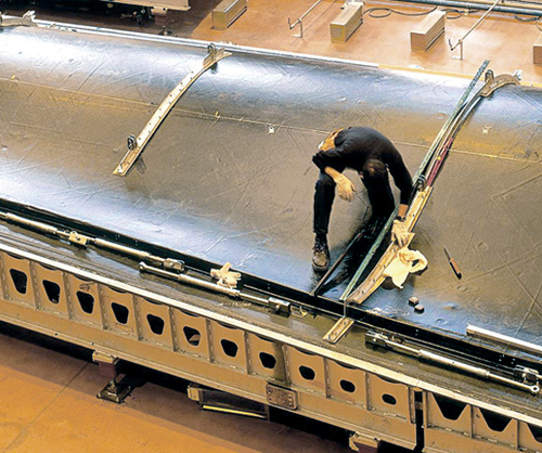
A technician checks the shape of a blade shell mold, achieved through an iterative process that balances structural integrity, material cost, manufacturability and produced power. Source: Gurit UK
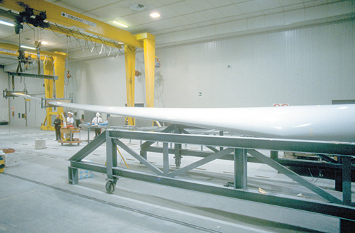
An important aspect of blade design is ensuring the component’s reliability and service life. Blade lifecycles are simulated with preproduction blade testing as shown in this photo. Source: Gurit UK
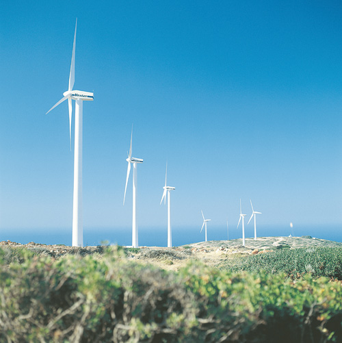
To date, the rotor blades for most wind turbines, such as these built by Vestas Wind Systems AS (Randers, Denmark) and installed on the island of Crete in Greece, have been designed for optimal operation in high-wind regimes. New blades that will enable the same turbines to operate efficiently in low-wind regimes must be longer and stiffer, but turbine design limits won’t allow increases in blade weight. Source: Vestas Wind Systems AS
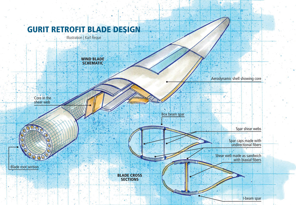
Illustration: Karl Reque


Engineering challenge:
Develop a re-engineered rotor blade for an existing wind turbine that can produce equivalent power in a wind regime different from the original design.
Design solution:
Selective use of high-performance prepreg in a resin-infused blade, coupled with design changes to blade structure, allows longer blade length for greater power at lower mean wind speed.


Double-digit growth in the wind energy industry is accelerating the demand for more powerful and efficient turbines, both onshore and offshore. But as wind farms proliferate, so do the engineering challenges. One particularly thorny design problem is retrofitting turbines originally designed for high-wind regimes with new blades re-engineered to accommodate less windy locales, says Julien Sellier, project engineer at Gurit (Isle of Wight, U.K.): “Typically, a new turbine and its blades will be engineered for International Electrotechnical Commission (IEC) Class I conditions, or an annual mean wind speed of 10 m/sec [39 ft/sec or 26.6 mph]. But, those ideal wind farm sites are fast disappearing. Most projects are now being sited in IEC Class 2 or IEC Class 3 locations.” The mean wind speed in Class 2 is 8.5 m/sec (27.9 ft/sec or 19.0 mph) and drops, in Class 3, to 7.5 m/sec (24.6 ft/sec or 16.8 mph). In order for that original turbine to generate the same rated power at a lower wind speed, changes must be made to the blade design. Since power increases with the square of the blade length, a longer blade is an obvious solution. It is not, however, an easy one.
Even for ideal wind conditions, blade design is complex, with many interrelated factors that have to be balanced. Speaking for many involved in blade design, Dayton Griffin, senior engineer with Global Energy Concepts (GEC, a Det Norske Veritas company, Seattle, Wash.) observes, “It’s an overall system design, with many conceptual choices that affect cost of energy. There isn’t one single solution — it involves aerodynamics, the structural design, the materials, the process and the manufacturing execution.” Redesigning blades for lower wind regimes ups the ante, says Sellier. “Both the structural and aerodynamics engineers need to ensure that the overall loading envelope for the new blade remains less than the original design loads,” he cautions. “That’s because blade mass and bending loads are approximately proportional to the cube of the blade length. Rotor mass thus increases faster than energy production, if care is not taken with the design. And if the new design is driven by maximum tip deflection to avoid tower strike, then it becomes even more difficult to engineer a longer blade.
A system design
“The turbine designer, the aerodynamicist and the structural engineer work together to achieve the design brief,” explains Dr. Damian Bannister, Gurit’s chief technology officer. “All of these areas are interdependent.” For example, the aerodynamics engineer tries to develop, ideally, a thin blade with a low thickness-to-chord ratio because this provides good aerodynamic efficiency. However, the structural engineer wants a high thickness-to-chord ratio for a more robust and durable component, while the turbine designer wants the lowest possible blade mass to minimize wear on generator parts. Several iterative design loops are needed to refine the design, during which both material quantities and aerodynamic performance affect the final cost of electricity. At each iteration, a new load calculation is required, because the loads depend on the weight of the blade.“The right solution is very different for each customer, depending on their turbines, their workforce, and their material supply chain,” says Bannister. “It’s a fluid, ‘live’ design, right up to the time the geometry is frozen to begin mold construction.” The time frame is generally tight, he adds, on the order of 12 months or less.
The process begins with the aerodynamicist, who develops an overall blade geometry (planform and airfoil sections) that is consistent with the power goals of the entire turbine system and that constrains the overall load taken by the rotor. For example, the amount of lift generated is dependent on blade chord dimension, blade twist and the airfoil shape. He or she looks at many load cases for all possible operational situations and then provides the structural engineer with a selection of design load cases for preliminary blade profile shapes that are representative of key operational parameters, says Sellier. The load cases will include extreme flapwise, or moment around the X-axis (chord axis); extreme edgewise, or the moment around the Y-axis (thickness axis); the equivalent fatigue, which assumes a 20-year life under continuously varying wind conditions; and worst tip deflection. The loads are calculated along x, y and z axes at several different locations along the length of the blade.
The structural engineer takes the load cases and begins to develop a preliminary design for the blade profile, using a suite of in-house-developed programs. When the conceived designs finally converge, finite element analysis (FEA) modeling is applied to determine modes of failure for the compromise design. Here, Gurit typically uses SolidWorks from SolidWorks Corp. (Concord, Mass.), HyperMesh from Altair Engineering Inc. (Troy, Mich.) and NASTRAN/PATRAN supplied by MSC.Software (Santa Ana, Calif.). The FEA models help validate the strength, stiffness and stability of the blade structure under the predicted loads.
Although blade designers are beginning to explore alternative concepts, Bannister says that, for now, most still employ “classic” solutions. For example, the blade root’s cylindrical shape is not only structurally efficient but also allows for attachment to the rotor via a pitch ring bearing that enables blade rotation to control pitch. Root size is driven by the size of the pitch bearing, and this, in turn, drives the design of the lower part of the blade, notes Sellier. This lower portion must have a very thick, strong laminate to resist the very high loads and bending moments in this region, especially in blades longer than 50m/160 ft.
Design of the “shell” or the body of the blade, which is almost always a cored sandwich construction, is driven largely by panel-buckling stability. “The choice of the core in a blade-engineering project adds to the engineering challenge by increasing the already large number of variables,” reports Sellier. Although balsa is a possibility, its comparatively high density and resin uptake exact a weight penalty. Foam cores are widely used for longer blades, with core thickness dependent on position in the blade shell: the closer to the root, the thicker the sandwich, Sellier points out, because the panels are larger there, particularly at the trailing edge. Ultimately, the choice is based on a number of factors, including mechanical properties, processing friendliness, temperature performance, resin uptake, material availability, kitting-service availability and overall cost. Bannister adds that the critical parameters of strength and stiffness are satisfied in the preliminary design, then skin stiffness, or core material type, can be tweaked in later iterations: “As we drill down, the details can be adjusted,” says Sellier.
Finally, the design of the blade spar, or principal load-bearing member — either a box beam or I-beam (see drawing at top, on right) — tends to be stiffness-driven for much of its length. Here, again, many factors are coupled in a complex array. Blades that are relatively stiff in the flapwise direction, to prevent tower strikes, tend to absorb the impact of transient wind loads and transmit those loads through the entire rotor/hub/drivetrain structure, increasing potential fatigue damage. More flexible blades can shed those loads, but they have a lower natural frequency of flapwise bending, says Sellier. Provided that the tower clearance design criterion is met, flapwise and edgewise frequencies need to be compared to the tower passing frequencies. But, the rotor overhang distance — that is, the distance that the rotor hub extends beyond the tower, which determines the amount of blade/tower clearance — doesn’t change significantly for longer blades. And if they are heavier than the legacy blades, Sellier points out, the new blades will put more load on the tower structure. “That’s why many designers consider unidirectional carbon for spars,” he explains, noting that carbon fiber reinforcement can “achieve the requisite blade stiffness with less material and different load distributions, and thus lower weight for the longer blade. This makes it possible to work within the existing overhang distance — again, a design trade-off that has to consider the entire system.”
Pushing the limits
For some customers, Gurit’s re-engineered blades are 30 percent larger than the originals. In these cases, several design strategies are typically considered, says Sellier: “The designer can play on the actual shape of the blade, whereas the engineer will tend to try to optimize the available materials on the market to create an efficient design.” Bannister adds that blade elements typically are varied in isolation on a base design to find the optimum solution for a given customer. For example, the width of the spar cap and its location can be changed for better structural efficiency. Thickness of the foil sections can be varied where the design is critical either strength-wise or stiffness-wise. Finally, the material type — carbon, glass or a hybrid solution — and the manufacturing method (infusion vs. prepreg) can be adjusted, he explains.For the past two years, Gurit blade retrofit strategy has included SparPreg, a unidirectional carbon/epoxy prepreg that can be used conventionally or used in place of dry reinforcement in infused blade designs. Although more costly than dry unidirectional fabric, it is formulated to facilitate air removal during bagging and cure. This results in very low void content and high fiber alignment, eliminating the risks associated with dry-fabric infusion. Used in place of glass reinforcement, SparPreg reportedly permits more efficient aerodynamic design — a thinner airfoil — as the requirement for cross-sectional inertia is offset by the higher modulus of the spar cap. Because it offers higher material properties than infused dry carbon, less material is needed for the spar, which helps the designer meet overall blade weight targets at longer lengths.
Beyond the limits
“People are struggling to go beyond the current limits of blade design technology, especially for very large offshore installations,” Bannister concludes. “There are fewer options now as blades get larger — infusion-based designs are reaching their limit, I believe. Reliability has to be maintained, but different design concepts are now needed.” These will likely include jointed or segmented designs and potentially different blade shapes, like the “flat-back” airfoils with thick trailing edges recently proposed by researchers at the University of California at Davis. GEC’s Griffin agrees, “We’re only scratching the surface right now, and we’ve got years of steady growth coming.”


.jpg;maxWidth=300;quality=90;format=webp)


Related Content

The basics of composite drawing interpretation
Knowing the fundamentals for reading drawings — including master ply tables, ply definition diagrams and more — lays a foundation for proper composite design evaluation.
Read More
ASCEND program update: Designing next-gen, high-rate auto and aerospace composites
GKN Aerospace, McLaren Automotive and U.K.-based partners share goals and progress aiming at high-rate, Industry 4.0-enabled, sustainable materials and processes.
Read More
Protecting EV motors more efficiently
Motors for electric vehicles are expected to benefit from Trelleborg’s thermoplastic composite rotor sleeve design, which advances materials and processes to produce a lightweight, energy-efficient component.
Read More
CFRTP enables better, greener smartphones
Carbon Mobile’s “monocoque” design eliminates separate case, cover and frame, better protects electronics and simplifies disassembly.
Read MoreRead Next

Anisotropic wind blade design expected to reduce wind-energy costs
Deliberately unbalanced laminate produces smoother power input from adaptive wind blades
Read More
Big Blades Cut Wind Energy Cost
Rapid growth rate of composite-intensive conversion systems drives market competition and innovation.
Read More
Carbon/glass hybrids used in composite wind turbine rotor blade design
As turbine blades grow to greater lengths, composite blade manufacturers take a long look at carbon/glass hybrids.
Read More