
Carbon fiber/PEEK takes hydraulic pump to new depths
A switch from metal to composites reduces weight, minimizes part deflection in ultradeep ocean installations.
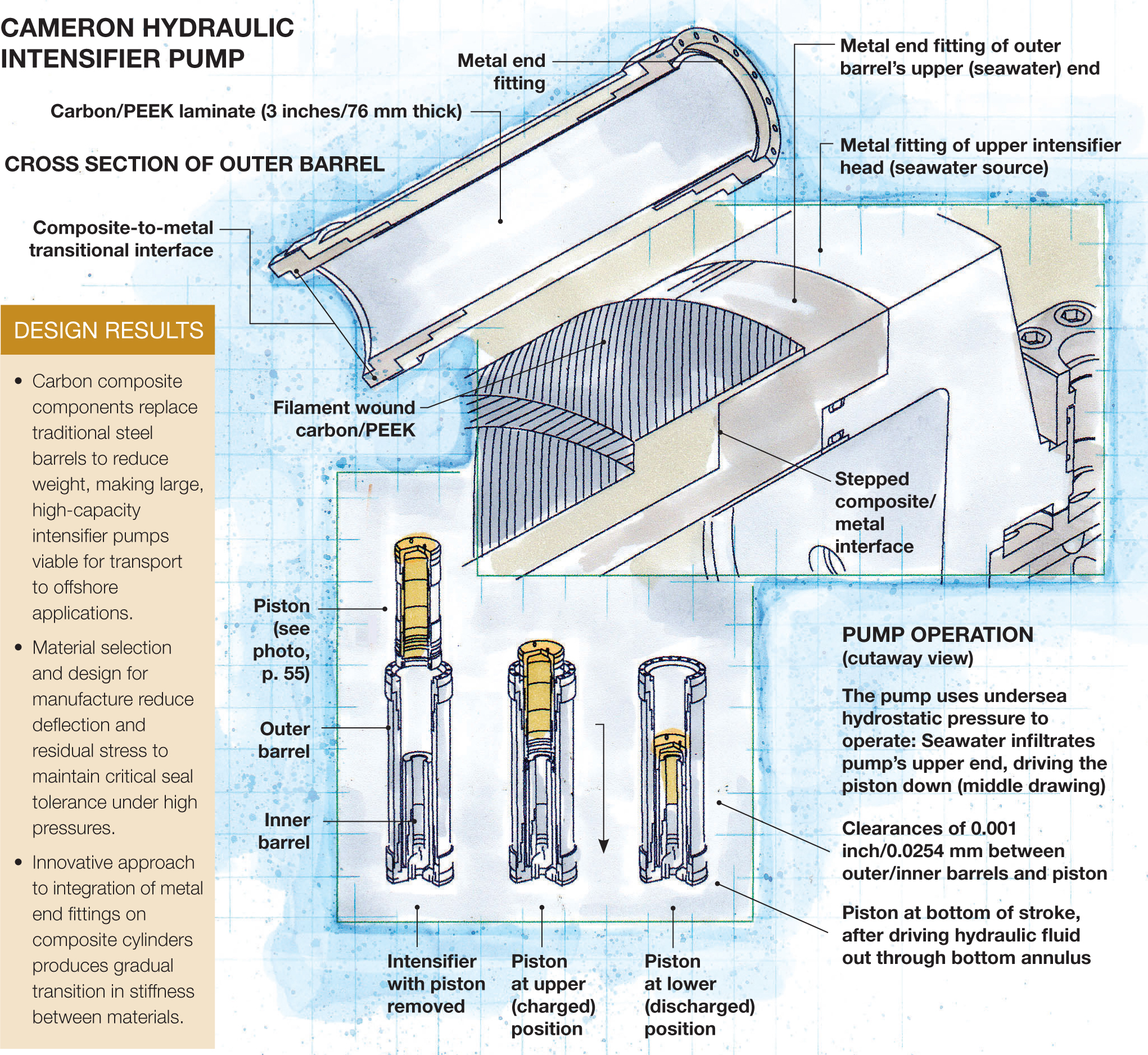
Cameron Hydraulic Intensifier Pump Illustration: Karl Reque
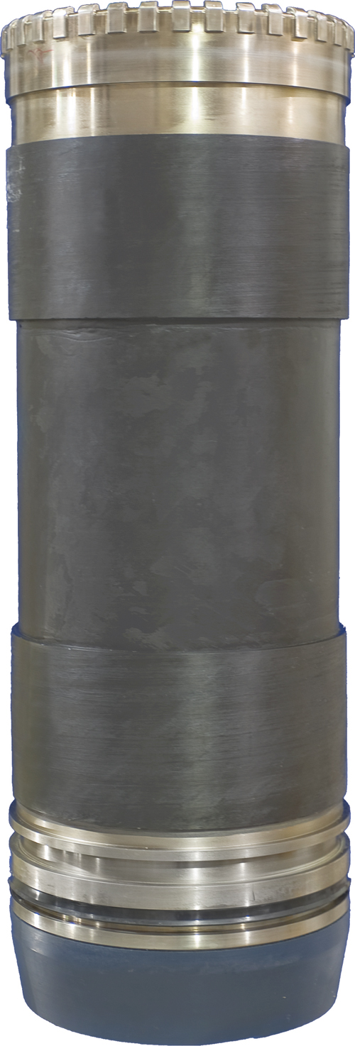
The intensifier pump's carbon composite outer barrel with metal end fittings on each end resists deflection via a 3-inch/76-mm thick carbon fiber-reinforced laminate. Source: Cameron
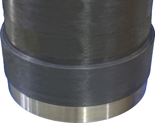
The composite-to-metal transition on the outercase (shown in close-up here) and other components was one of the biggest challenges. Source: Cameron
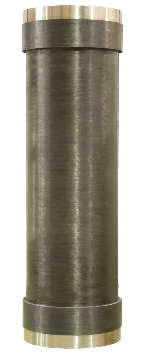
The intensifier pump's piston (shown here) rides up and down between the outer and inner barrels. Source: Cameron


Design Results:
- Carbon composite components replace traditional steel barrels to reduce weight, making large, high-capacity intensifier pumps viable for transport to offshore applications.
- Material selection and design for manufacture reduce deflection and residual stress to maintain critical seal tolerance under high pressures.
- Innovative approach to integration of metal end fittings on composite cylinders produces gradual transition in stiffness between materials.
Placing and maintaining machinery on the ocean floor is a challenge at any depth, but the deeper the placement, the more hostile the environment. In ultradeep water, equipment is not only immersed in corrosive saltwater, but it also must endure low temperatures and withstand enormous water pressure. One new deepwater solution, a large-capacity hydraulic intensifier pump from Houston, Texas-based Cameron International Corp., is facing these challenges with a proprietary new pump design that takes advantage of the water pressure and involves a switch from traditional metals to a carbon fiber composite for critical components.


“It’s a radical design response,” says Cameron’s principal research engineer, Don Coonrod. “As we go into deeper and deeper waters, new innovations are required.”
Cameron supplies flow equipment and systems to the worldwide oil, gas and process industries. Its large-capacity carbon composite intensifier pump is able to operate at depths to 15,000 ft/4,752m — the result of a three-year collaborative effort between Cameron and composites equipment and structures manufacturer Automated Dynamics (Schenectady, N.Y.).
“By using a high-performance carbon fiber and PEEK [polyetheretherketone] matrix composite in conjunction with precise fiber placement technologies, we minimize water absorption, marine bio-fouling and weight while optimizing the material construction to meet the demanding functional and form-fit requirements,” says James Harty, VP sales and marketing at Automated Dynamics.
A new approach to hydraulic intensification
“In the initial design phase, we had to ask ourselves, How do we design a part that faces tremendous pressures — both external and internal — and ensure that the cylinders don’t collapse or, when the pump actuates, it doesn’t deform beyond limits and break the seal or jam?” explains Dr. Ronald B. Bucinell, P.E., of the Department of Mechanical Engineering at Union College (Schenectady, N.Y.), who conducted finite element analysis (FEA) on the component. The solution was complex and affected all aspects of pump design and manufacture.
Unlike traditional rod-and-piston systems, this unit incorporates three major composite components — the outer housing, the inner housing and the piston — as three concentric cylinders.
“This design presents unique materials engineering challenges to support its operational benefits,” says Brett Kimball, project engineer at Automated Dynamics. For example, the volumetric capacity for the prototype pump is approximately 30 gal/113.6L per stroke. The concentric piston uses inside-diameter (ID) and outside-diameter (OD) seals against the outer barrel and inner barrel. Accordingly, the components are designed to limit deflection in order to maintain seal extrusion gap requirements. The intensifier’s dynamic seal addresses differential pressures — as the piston moves up and down — of 11,000 psi/758 bar across the piston/inner barrel boundary and 7,500 psi/517 bar across the piston/outer barrel boundary, says Coonrod. The concentric design creates a 1-atmosphere volume within the ID of the inner barrel and extends into the variable volume inside the concentric piston as it moves up and down over the inner barrel. This unique design allows for seepage across the 11,000-psi dynamic seal without hydraulically locking the piston, which is a risk associated with rod-and-piston intensifiers.
Significantly, the ID volume of the inner barrel now houses internal instrumentation and control system electronics, eliminating the need for external instrumentation pressure vessels. It also allows for monitoring liquid ingress from dynamic seal seepage (a much more complex function in rod-and-piston designs).
Minimizing deflection
The selection of Hexcel’s (Stamford, Conn.) AS4 carbon fiber/PEEK was driven primarily by the need to minimize deflection of the inner and outer barrels. “The hoop and axial directions in the cylinder walls have reinforcement from the carbon fiber, but through the thickness is more compliant as the transverse properties of the fibers have only minimal effect,” says Bucinell. “The majority of properties come from the thermoplastic, and with pressures squeezing in on both sides, these properties can have a big impact on maintaining tolerances.”
AS4 continuous carbon fiber was chosen for its stiffness and corrosion resistance. “Unlike glass, carbon fiber doesn’t require sizing, which can be a liability in corrosive seawater,” explains Kimball. “Stiffer fibers are available but are difficult to obtain in a prepreg. The ability to handle extremely stiff fibers without sizing is a major challenge for prepreg suppliers,” he adds.
Automated Dynamics gets qualified PEEK from several suppliers, including Cytec Engineered Materials (Tempe, Ariz.) and TenCate Advanced Composites USA (Morgan Hill, Calif.). PEEK also offers the benefit of an abundance of material data, says Kimball. He adds that polyetherketoneketone (PEKK) and polyphenylene sulfide (PPS) are under consideration for future parts.
One area of continued debate is whether to use a thin stainless steel liner between the piston and the inner barrel. Mounted in the inner barrel, the liner would function only as a high-pressure sealing surface and would not be necessary for structural support.
“By using the liner, we gain the advantage of the hoop and axial stiffness provided by the composite, which minimizes deformation to external pressures, while at the same time we provide a proven surface for the seal — a surface on which we have a large database of knowledge,” explains Bucinell.
The transition from composite to metal
Although an all-composite design was considered, metal end fittings ensured that the new pump would be compatible with existing metal fixtures on equipment to which the intensifier will be attached. One of the biggest design issues was the transition between each composite cylinder and its metal fittings. “It’s always a challenge to taper the stiffness of the composite part into the metal part so that you maintain a nice transition of stress and don’t get premature failures,” says Bucinell.
The solution was more than two years in the making. “We went through a few different design cycles and design concepts to optimize the interface between the end fittings and the composite,” says Kimball. “It was critical, not only from a part functionality standpoint, but also from a manufacturing standpoint.”
“We … needed to maintain enough of an interface between the more compliant composite and the very stiff metal to form a strong bond that could withstand the operating pressures,” explains Kimball. “Too little metal could cause too high of a stress concentration at the transition from the metal to the composite, while too much metal, or surface area, adds unnecessarily to the overall weight of the part.”
To achieve the right balance and create a smooth transition of stress, a series of sample pieces — metal overwound with composite — were run through a series of tests, including FEA and materials and tensile testing, to evaluate the manufacturability of the production articles. “We also had to make sure that the transitions from composite to metal occurred in the right places,” adds Bucinell. “We didn’t want the seal to be going over a composite-metal interface.”
“In a more complex structure, if there were stress problems around the metal, we could change the wind and gradient of the composite material’s properties as it got closer to the metal,” he says, noting that such changes would drive up the manufacturing cost. “Luckily, that wasn’t warranted here.”
Instead, Automated Dynamics was able to optimize the transition by tapering the geometry. “We gradually increase the contribution of the metal to the load-carrying capabilities of the composite,” Bucinell explains. “If that’s done slowly enough, then it’s typically not necessary to change the wind in the axial direction.”
For each of the three cylinders, a proprietary multistep manufacturing process is now used to concurrently build the composite and metal end fittings into one integrated structure. The metal fittings feature a multipiece design. The pieces are interleaved with the composite. The fiber placement head makes a pass and then a section of the metal fitting is installed; then another wind occurs, followed by placement of another metal section, and so on.
Fiber placement reduces residual stresses
Throughout the design process, manufacturability was of critical concern. “The design isn’t independent of the manufacturing,” stresses Bucinell. “You can’t design without understanding the manufacturing process that’s going to be used.”
Three primary goals were established. “If any of these manufacturing targets are missed, we lose our 0.001-inch [0.0254-mm] clearance and the parts won’t fit together properly,” stresses Bucinell. “First, we needed to produce a near-net shape via fiber placement,” he says. Automated Dynamics’ proprietary fiber placement process uses unidirectional prepreg with high heat and pressure to consolidate the structure in situ with no postprocessing. “This technology allows us to orient the reinforcing fiber from 0° [axial] to 90° [hoop] and anywhere in between, which played a big part in the design,” says Kimball.
“Secondly, no residual stress could be introduced during manufacturing,” says Bucinell. The process itself, with no required postcuring, eliminates residual stress. “In an autoclave cure using a thermoset, you wind up the barrel, put it in the autoclave, and then cool it. The steady state for the material is at the cure temperature, around 400°F [204°C],” says Bucinell. “So, as you bring the temperature down, residual stress builds up.” Although it is a desirable state in some applications, he says that “in a compressive environment, like this one, it’s critical to minimize residual stress. Otherwise, all of the advantages of the plies working together to maintain tight tolerances is lost and interlaminar stresses build up, which under the right stress conditions can cause catastrophic delamination.”
“Lastly,” Bucinell notes, “we needed to minimize the stresses associated with winding.” This was done by avoiding heavy tensions, which build up a state of stress within the composite. “We were able to minimize interlaminar stresses in the layup through the function of how we feather in the geometry,” he explains.
The layup design and the wall thickness that would meet the seal requirements were determined and tested in parallel. “One didn’t drive the other,” adds Kimball. “With wall thicknesses in excess of 3 inches [76 mm], strength was not the issue, but rather stiffness.”
The new intensifier pump is currently undergoing qualification testing, and Cameron is evaluating nondestructive inspection techniques to be used in conjunction with functional testing of the system.


.jpg;maxWidth=300;quality=90;format=webp)


Related Content

Materials & Processes: Composites fibers and resins
Compared to legacy materials like steel, aluminum, iron and titanium, composites are still coming of age, and only just now are being better understood by design and manufacturing engineers. However, composites’ physical properties — combined with unbeatable light weight — make them undeniably attractive.
Read More
Materials & Processes: Fibers for composites
The structural properties of composite materials are derived primarily from the fiber reinforcement. Fiber types, their manufacture, their uses and the end-market applications in which they find most use are described.
Read More
Plant tour: Joby Aviation, Marina, Calif., U.S.
As the advanced air mobility market begins to take shape, market leader Joby Aviation works to industrialize composites manufacturing for its first-generation, composites-intensive, all-electric air taxi.
Read More
One-piece, one-shot, 17-meter wing spar for high-rate aircraft manufacture
GKN Aerospace has spent the last five years developing materials strategies and resin transfer molding (RTM) for an aircraft trailing edge wing spar for the Airbus Wing of Tomorrow program.
Read MoreRead Next

Composites end markets: Energy (2024)
Composites are used widely in oil/gas, wind and other renewable energy applications. Despite market challenges, growth potential and innovation for composites continue.
Read More
CW’s 2024 Top Shops survey offers new approach to benchmarking
Respondents that complete the survey by April 30, 2024, have the chance to be recognized as an honoree.
Read More
From the CW Archives: The tale of the thermoplastic cryotank
In 2006, guest columnist Bob Hartunian related the story of his efforts two decades prior, while at McDonnell Douglas, to develop a thermoplastic composite crytank for hydrogen storage. He learned a lot of lessons.
Read More