Carbon fiber as a replacement for glass fiber in D-LFT auto parts
Research progresses toward attainment of 80-90% of continuous carbon fiber tensile modulus in lighter parts molded from direct long fiber thermoplastic compounds.
The automotive industry has used glass fibers in direct, long-fiber thermoplastic (D-LFT) manufacturing for many years to produce a variety of parts, among them battery trays, load floors and spare-wheel wells. Long-fiber thermoplastics are a type of composite material wherein thermoplastic polymers are mixed with chopped fiber reinforcements of nominal 6 mm length.
Recently, high-modulus, lightweight carbon fibers were studied as a drop-in replacement for chopped glass fibers in D-LFT, as a means to help automakers simultaneously improve part performance and reduce vehicle weight, fuel consumption and CO2 emissions in anticipation of US government Corporate Average Fuel Economy (CAFE) mandates. CAFE currently calls for an average of about 29 mpge (mile-per-gallon equivalent; that is, either mpg for internal combustion engines, or an equivalent degree of energy efficiency — mpge — in an alternative mode of propulsion), with gradual increases to 35.5 mpge, by 2016.
The study and its results were first presented at SAMPE Tech Seattle (June 2-5, 2014), by George Husman, the now retired chief technology officer for Zoltek Corp. (St. Louis, MO, US), and, subsequently, at the SPE Automotive Composites Conference & Exposition Sept 9-11, 2014, (Novi, MI, US). Husman summarized study findings recorded in a paper titled “Mechanical Study of Direct Long Fiber Thermoplastic Carbon/Polyamide 6 and Its Relations to Processing Parameters,” by Kyle Rohan and T.J. McDonough of Zoltek with Vanja Ugresic, Eva Potyra and Frank Henning from the Fraunhofer Project Centre for Composites Research University of Western Ontario (London, ON, Canada).
Materials and process
Although the D-LFT process can be used with a variety of thermoplastic resins and reinforcing fiber combinations, the automotive industry commonly uses polypropylene (PP) and glass fibers in LFT and D-LFT processing. For that reason, PP was considered for this study, due to its good processability, resistance to organic solvents and its hydrophobic quality. But David Purcell, Zoltek’s executive VP, says that ultimately, “we opted for carbon fiber and polyamide 6 [PA6] as that combination is a common request from the automotive industry.”
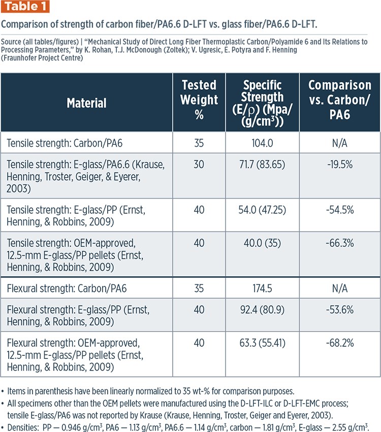
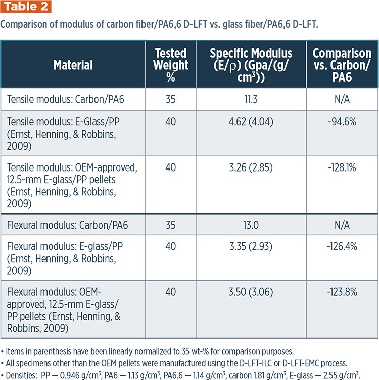
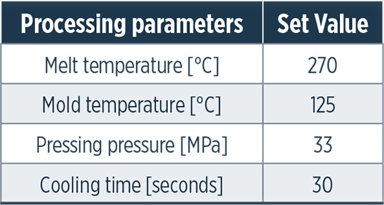
PP, he explains, typically exhibits relatively lower mechanical properties and service temperatures when compared to an engineered thermoplastic, such as PA6. So, despite PA processing drawbacks, such as higher processing temperatures (see Tables 1 & 2, at left) and greater water absorption, it was judged the better candidate for the intended purpose. Specifically, Zoltek’s Panex 35 (50K) carbon fiber and a PA6 thermoplastic matrix from an unspecified source were selected for the experiments conducted in the study.
LFT processing technologies vary, and the type of technology affects the end properties in the part. One type uses glass mat reinforcement commingled with glass thermoplastic sheets. Another, indirect LFT processing, uses pellets for injection molding. Relatively new direct LFT technology combines the fiber and matrix immediately before the compound enters the mold; the compound can then be processed either by direct injection molding (LFT-D-IMC) or by extruder compression molding (LFT-D-ECM).
LFT-D-ECM was selected for this study because, first, unlike other LFT systems, it uses two extruders and, thus, separates the compounding and fiber-mixing steps. Therefore, both extruders can be individually optimized for their specific functions. Second, the material is not subjected to the same high levels of stress typical in injection molding, and, therefore, there is less fiber breakage and, in turn, better mechanical properties in the part.
Immediate improvement
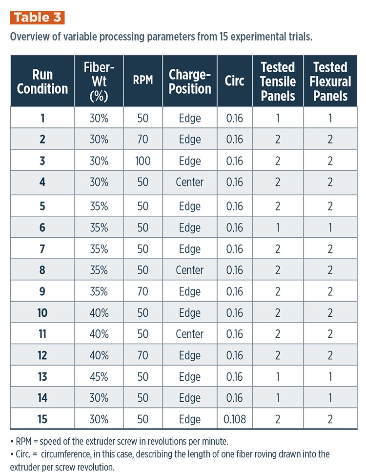
Fifteen experiments were run for the study, each with different processing conditions (Table 3), but the parameters for all were constant (See Table 4). The study concluded that the selected carbon fiber/polyamide D-LFT material system provided immediate improvement in mechanical properties compared with glass fiber D-LFT, especially in stiffness (tensile modulus, or modulus of elasticity, the measure of tensile stress to elongation).
“Tensile strength will be lower than it is in a continuous fiber format, but in automotive parts and consumer electronics applications, modulus is actually more critical for meeting specific stiffness design requirements,” Purcell explains, “and stiffness is governed by the modulus and weight of the chosen material.” As a bonus for manufacturing economics, the improved properties were shown to be achievable using currently available equipment, with minor modifications.
Another advantage of carbon fiber for this material system is its high modulus, and the relationship of modulus translation to fiber aspect ratio in the final composite, Purcell says.
Modulus translation
It is known that the strength of a composite part is primarily a function of the fiber reinforcement. The greatest strength is provided by continuous fiber, and the use of chopped fibers, rather than continuous fibers, considerably decreases the strength of the final part. However, there is evidence that longer segments of chopped fiber in parallel orientation, or distribution, will cause the part to have strength approaching the strength provided by the continuous carbon tow. This phenomenon is explicated in the Halpin-Tsai isotropic approximation for longitudinal and transverse moduli, developed by J.C. Halpin at Wright Patterson Air Force Base (WPAFB, Dayton, OH, US) and Stephen W. Tsai, professor emeritus, Structures and Composites Laboratory, Stanford University (Stanford, CA, US).
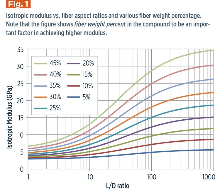
The Halpin-Tsai equations show that if an aspect ratio (L/D) of 100 — 0.72 mm length/0.0072 mm diameter in the case of carbon fiber — can be reached, then the mechanical strength of the fiber will be about 21.5 GPa in tensile modulus, or 83% of the 26 GPa theoretical maximum modulus for a molded laminate that is 35% by weight of carbon fiber with PA6 polymer.
Purcell notes that in the trials, some fibers retained lengths of as much as 2 mm, but the average length was much shorter. “Because we had some fibers that made it through the process at 2 mm, it shows that it’s technically possible to make it happen,” he notes, but emphasizes that “it’s the average fiber length that matters more and drives the mechanical performance. A few fibers at 2 mm length did not seem to contribute to the mechanical performance.” In any case, the theoretical curve flattens out above the L/D ratio of 100, delivering diminishing benefits as fiber length increases. Thus, the theoretical estimated fiber translation (modulus translation) for the same part at a fiber aspect ratio of 278 — that for an average 2 mm fiber length — is ~24.5 GPa, or 94% of the 26 GPa theoretical maximum. While the higher L/D is better, attaining 2 mm length would be a considerable challenge, for only a 10-11% improvement in properties (see Fig. 1, at left).
In Zoltek’s study, the actual properties measured were consistent with the theoretical curves. The majority of the study samples held L/D ratios between 14 and 42; that is 0.1 to 0.3 mm length in the final molded laminate. “More work is needed to drive up the fiber lengths to at least 0.72 mm average and, ideally, 1 to 2 mm average in the final end product,” Purcell says.
Findings and future directions
Although the average length of chopped fiber is 6 mm in its raw condition, the fiber breaks down during compounding with the matrix into pellet form — in this case, the thermoplastic polymer — and further breaks down when the pellets are injection or compression molded. Purcell notes that carbon fibers are more prone to fracturing than glass fibers when processed through a twin-screw extruder with a high-viscosity thermoplastic polymer, thus resulting in final fiber lengths in the 0.1-0.3 mm range. The final mechanical strength of the composite part is further compromised by uneven distribution of the fiber during processing. They key to success, then, is striking that balance of uniform fiber distribution while maintaining fiber length, which requires adjustments to the polymer chemistry (for lower viscosity) and twin-screw design (to be gentler on the fibers).
“Based on our findings in the fiber length and, therefore, mechanical performance, there are more adjustments needed to the process — specifically in the screw design and polymer chemistry/viscosity to reduce the fiber breakage,” Purcell says.
Although long-fiber chopped carbon was randomly oriented in the compound and, therefore, in the cured test panels, the mechanical performance was consistently better in the flow direction than the cross-flow direction. This directionality became stronger the farther that the material flowed during the pressing operation. However, despite this directionality effect, the fiber weight percentage remained relatively consistent across the panel. It was also observed that the shorter fibers appear to influence performance more than the longer fibers, possibly due to the tendency of the longer fibers to bundle together.
Results of the study clearly warrant additional R&D of carbon/PA6 D-LFT as a means of improving mechanical performance in parts now made with standard glass LFT in the auto industry — and in other markets that require “high throughput and low cycle times with little to no scrap,” Purcell says. Although Zoltek has done no further investigation into this technology to date, he adds, it will in the near future. Goals include extending fiber lengths and improving fiber distribution to achieve greater mechanical strength. Purcell concludes, “What is important to understand are the lessons learned and what must be studied next to improve the process parameters to achieve the goal of 2-mm-long fibers.”
Related Content
Recycling end-of-life composite parts: New methods, markets
From infrastructure solutions to consumer products, Polish recycler Anmet and Netherlands-based researchers are developing new methods for repurposing wind turbine blades and other composite parts.
Read MorePrice, performance, protection: EV battery enclosures, Part 1
Composite technologies are growing in use as suppliers continue efforts to meet more demanding requirements for EV battery enclosures.
Read MoreMaterials & Processes: Composites fibers and resins
Compared to legacy materials like steel, aluminum, iron and titanium, composites are still coming of age, and only just now are being better understood by design and manufacturing engineers. However, composites’ physical properties — combined with unbeatable light weight — make them undeniably attractive.
Read MoreThe making of carbon fiber
A look at the process by which precursor becomes carbon fiber through a careful (and mostly proprietary) manipulation of temperature and tension.
Read MoreRead Next
From the CW Archives: The tale of the thermoplastic cryotank
In 2006, guest columnist Bob Hartunian related the story of his efforts two decades prior, while at McDonnell Douglas, to develop a thermoplastic composite crytank for hydrogen storage. He learned a lot of lessons.
Read MoreCW’s 2024 Top Shops survey offers new approach to benchmarking
Respondents that complete the survey by April 30, 2024, have the chance to be recognized as an honoree.
Read MoreComposites end markets: Energy (2024)
Composites are used widely in oil/gas, wind and other renewable energy applications. Despite market challenges, growth potential and innovation for composites continue.
Read More





.jpg;maxWidth=300;quality=90)

