
Bi-angle fabrics find first commercial application
Bicycle manufacturer sees dramatic productivity gains using unbalanced fabrics conceived at Stanford University and manufactured by Chomarat.

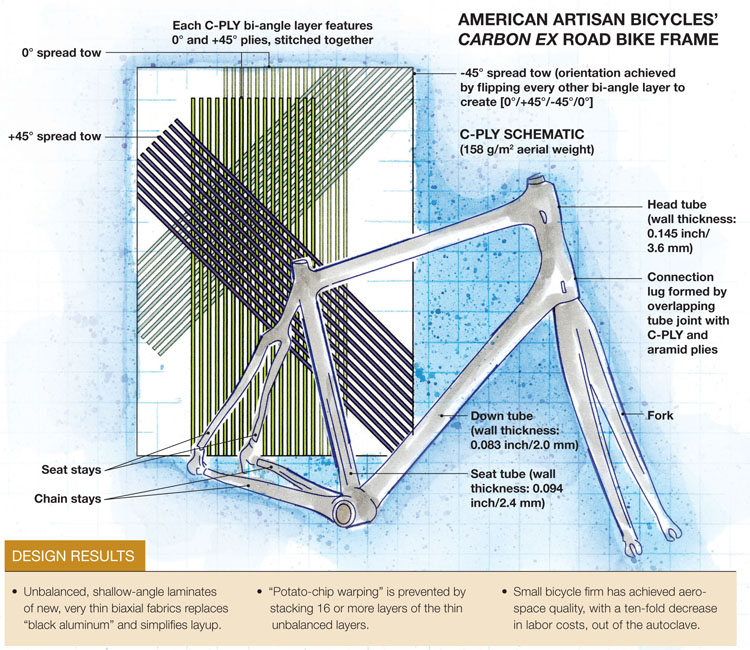
American Artisan Bicycles' Carbon EX Road Bike Frame. Illustration: Karl Reque
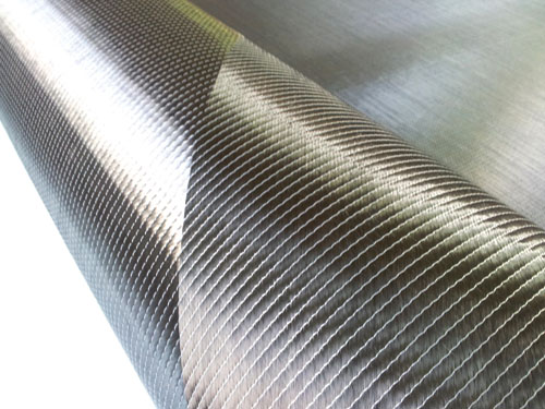
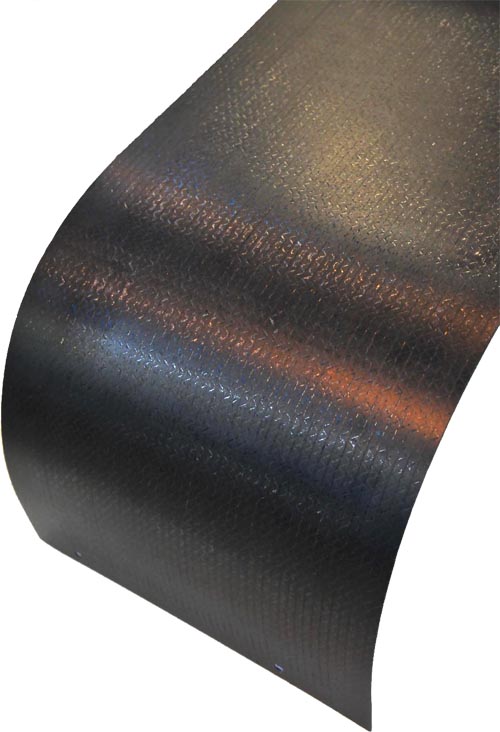
C-PLY material, manufactured by Chomarat (Le Cheylard, France), features two plies of carbon fiber, at 0° and a shallow angle (shown here at 45°), stitched together. C-PLY reportedly enables Sonoma, Calif.-based American Artisan Bicycles to achieve part quality and performance usually seen only in much more expensive autoclaved parts. Source: Chomarat
An H-46 Chinook helicopter tunnel cover prototype, made with vacuum-infused C-PLY by VX Aerospace (Morganton, N.C.). Source: Chomarat
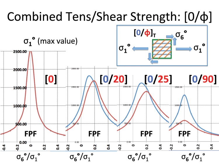
Fig. 1: This diagram, output from MIC-MAC software, shows that shallower cross-ply angles better withstand first-ply failure. Source: Chomarat


Design Results:
• Unbalanced, shallow-angle laminates of new, very thin biaxial fabrics replaces “black aluminum” and simplifies layup.
• “Potato-chip warping” is prevented by stacking 16 or more layers of the thin unbalanced layers.
• Small bicycle firm has achieved aerospace quality, with a ten-fold decrease in labor costs, out of the autoclave.


For decades the composites industry has emulated the homogeneous properties of metals, designing quasi-isotropic structural laminates with stacked unidirectional tapes — “black aluminum.” The classic 0°/90°/+45°/-45° layup has predominated not only because resulting laminates exhibit similar stiffness in all directions, but also because it minimizes bending/twist coupling and gives metal-centric engineers more confidence. But this symmetrical and, until recently, sacrosanct configuration, could be giving way to a unique alternative.
“I had this idea for a very long time that there was a way to relax these design rules and achieve optimized results with asymmetrical layups,” recalls the alternative’s inventor, Dr. Stephen Tsai, professor emeritus at Stanford University (Palo Alto, Calif.). In fact, Tsai and the late Edward M. Wu first addressed the issue in 1971, when they introduced the Tsai-Wu Failure Criterion (see "End Note" at bottom of article). In the paper’s introduction, they contended that a more reasonable approach was to stack alternating unbalanced (anisotropic) layers (e.g., 0° and a shallow angle). Forty years later, this “bi-angle” concept (pat. pend.) has found its first commercial application in a new production bicycle frame from American Artisan Bicycles (Sonoma, Calif.).
Bye-bye, black aluminum
Why bi-angle material? The answer lies in the mathematical prediction of laminate failure, traditionally a difficult subject due to the multiple plies in various directions, differences in material properties from ply to ply and even outside influences, such as temperature or moisture. In a nutshell, if a quasi-isotropic laminate is subjected to increasing load in the direction of the 0° fibers, matrix cracking eventually occurs in the off-axis or transverse plies. This phenomenon, known as first-ply failure, decreases matrix stiffness. Eventually, as loads increase, ultimate, or last-ply, failure occurs. The load levels at the two failure points and the difference between them depend on the layup and the fiber/resin combination, among other factors.
“You put load on a quasi-isotropic laminate and the off-axis plies fail early and microcrack, due to shear,” says Bob Skillen, founder and chief engineer at VX Aerospace (Morganton, N.C.), who has tested the material in aerospace parts. “You’re essentially accepting microcracking in your design,” he contends, but he points out that “there’s no reason to do that.”
Because early methods for predicting progressive failure were unsophisticated, says one industry analysis expert, most designers compensated with conservative first-ply-failure solutions. But adding “insurance” plies — overdesigning — sacrifices the design advantages of composites (see “Virtual testing of composites: Beyond make & break,” under "Editor's Picks," at top right). Tsai, therefore, pushed non-quasi-isotropic designs over the years and even developed spreadsheet-based failure analysis software, called MIC-MAC (for micro-macromechanical analysis), which quickly calculates optimized layups at any angle and predicts how they will behave, and fail, under load. Fig. 1, shows that when the cross-ply angle is reduced in relation to the 0° direction, the resulting laminate withstands significantly greater stress before first-ply failure and last-ply failure and generally performs better in many load applications, thanks to the reduction in interlaminar forces. The figure also shows that the stresses that cause first-ply failure and last-ply failure equalize at a cross-ply angle of about 20°. Concern that very low-angle cross plies might result in “potato-chip warping” of the laminate is alleviated, says Tsai, if enough layers are stacked together. “The difference between symmetrical and asymmetrical laminates disappears when 16 or more bi-angle layers are stacked,” he explains. “Continuous stacking makes the location of plies, and reversing the order of stacking relative to the mid-plane, irrelevant.” In other words, the large number of repeated layers effectively homogenizes the laminate.
The unexpected result is mechanical performance that matches that of autoclaved uni prepreg tapes, via easier vacuum-bag processing. Moreover, the resulting laminate is lighter and thinner than a quasi-isotropic counterpart because “more, thinner plies make a stronger and tougher part than fewer, thicker plies,” Skillen explains.
Such a layup also has a >30 percent higher first natural frequency, a factor that often dominates laminate design, Tsai adds. With a higher first natural frequency, the operating range of the part in terms of vibration performance is greater.
From theory to practice
Tsai knew, however, that hand cutting of shallow angles using uni tapes was impractical. The key was to make available a fabric with 0° and a shallow angle already plied together, which would enable fast fabrication and adapt the bi-angle concept to automated processing. Tsai found a partner in Michel Cognet, group managing director of Chomarat (Le Cheylard, France). The textile specialist now manufactures noncrimp bi-angle fabrics called C-PLY, which can be converted to prepregs by Aldila (Poway, Calif.). Brian Laufenberg, president of Chomarat North America (Anderson, S.C.), says conventional multiaxial machinery can assemble cross plies to about 45°, but Chomarat’s equipment can combine 0° fibers with off-axis plies as acute as 20°. The company’s efficient tow-spreading process can produce fabrics at areal weights as low as 75 g/m2, and ongoing development is likely to reduce weight further. Chomarat thus can provide a complete range of thin, low-areal-weight, spread-tow, multiaxial noncrimp C-PLY fabrics.
C-PLY laminates were first trialed in 2010 by Dr. Alan Nettles, a visiting scholar at Stanford. His extensive coupon testing under static and impact loading scenarios showed that infused bi-angle laminates are virtually equal in performance to unidirectional prepreg.
A material change
After discussions with Tsai, Dr. John Eggers, who holds a certificate in composite design from Stanford and is the founder and CEO of the nonprofit cooperative American Artisan Bicycles, converted his company’s Carbon EX road bike frame from prepreg layup to infused C-PLY. His team had previously designed the frame using engineering software program Adobe Inventor, supplied by Adobe Systems Inc. (San Jose, Calif.), MIC-MAC from Stanford’s Composites Design Group and bicycle frame-specific BikeCAD Pro from The Bicycle Forest Inc. (Kitchener-Waterloo, Ontario, Canada). Intermediate-modulus, 300 g/m2 uni carbon fiber prepreg was originally selected for the top tube, head tube, down tube and seat tube, and woven small-tow fabric combined with a titanium mesh was selected for the rear triangle (or seat/chain stays). The lugs (tube connections) were made by overwrapping joints with woven carbon and aramid fabrics; the latter was used to improve “shock absorption,” says Eggers.
“Using 0° and ±45° directions is the ‘standard’ layup orientation in carbon bike frames worldwide. Of course we tried different angles, including ±25 and ±77, as well as all three at the same time,” Eggers recalls. “We found that tube breaking strength was the highest using the ±45 orientation. But, it was a real headache for us, and very time-consuming, to produce balanced and symmetrical layups by cutting 45° angles manually from uni prepreg tapes. It was difficult to get right.” He adds that managing prepreg shipments, freezer storage and out-time increased the difficulty and led to wasted materials.
With help from Tsai and Stanford’s Composites Design Group, the Carbon EX frame was reset for the new material. The previous layup involved four unidirectional prepreg tape plies (0°/+45°/-45°/0°) inside two-piece tube molds. Follow-up analysis by Eggers and the Stanford team showed that four C-PLY layers — each a 0° ply of uni 12K stitched to a +45° ply of 12K (both high-strength carbon at an areal weight of 79 g/m2) — is sufficient for the top and down tubes. Eight carbon plies result in a wall thickness of 0.083 inch/2 mm. To create the +45° and -45° orientations, every other C-PLY layer is flipped. To prevent mold slippage, plies are secured with tackifier, reports Eggers. For the seat tube, 10 C-PLY layers are used (20 total plies) for a wall thickness of 0.094 inch/2.4 mm. For the head tube, which must withstand frontal impact, 16 C-PLY layers (32 plies) form a tube wall of 0.145-inch/3.6-mm thickness.
The layups are infused with West System (Bay City, Mich.) epoxy in a heat-assisted light resin transfer molding (LRTM) process. Demolded tubes are mitered, placed in an assembly jig and tacked together with high-density structural epoxy filler. Then the lugs are hand wrapped, using wet out C-PLY and woven aramid. Cured frame assemblies are primed and painted.
Eggers reports that there is no significant wall thickness difference between the original uni prepreg tubes and the infused C-PLY tubes: “The C-PLY’s extreme thinness and light areal weight results in very light yet very strong tubes.”
Material processing, claims Eggers, is “dramatically faster.” Hand layup of prepreg took 40 hours per frame. Now, a frame can be produced with C-PLY in only four hours. “There are no problems with dry spots or voids,” he adds. Frame testing confirms better mechanicals and riders report a “better ride.” The new material “is a bonus,” he sums up. “This has really helped our company’s mission of producing bikes in the U.S. at a competitive price ... with autoclave quality.”
Today, 23 Carbon EX frame sizes, classed in five stiffness regimes, provide a near-custom fit for a wide range of riders. Chomarat’s Laufenberg, however, expects wider application: “An unbalanced 0°/25° layup, for example, can take advantage of shear coupling to reduce bending and twisting in wing-type structures or wind blades.” Aerospace industry curiosity is high. Skillen at VX Aerospace is reporting good results from using C-PLY in some rotorcraft test articles and C-PLY is under consideration by other airframers, notably Spirit Aerosystems Inc. (Wichita, Kan.).
End Note: Tsai and Wu published their failure criterion findings in “A General Theory of Strength for Anisotropic Materials,” Journal of Composite Materials, 1971, Vol. 5, pp. 58-80.


.jpg;maxWidth=300;quality=90;format=webp)


Related Content

Colored carbon fiber composite bike wheels launched at The Cycle Show
Wheel brand Parcours reveals composite bike wheels using Hypetex colored carbon fiber to achieve aesthetic, lightweight and performance goals.
Read More
Aluula introduces lightweight composite materials for wind sports and beyond
The company’s proprietary UHMWPE fabrics combined with technical films in a patented fusion process are said to increase performance and recyclability.
Read More
Toray rCF from Boeing 787 is incorporated into ultra-light laptops
Torayca-based aerospace components have successfully been repurposed into the Lenovo ThinkPad X1 Carbon Gen 12, highlighting the ongoing application of recycled composites.
Read More
Carbon Mobile, SABIC to develop, deploy advanced carbon fiber in connected devices
Collaboration aims to deliver the next generation of thinner, lighter, stronger and more sustainable composite materials used in consumer electronics and automotive industries.
Read MoreRead Next

Virtual testing of composites: Beyond make & break
Software-based micromechanical modeling and analysis methods promise faster and more cost-effective aircraft development and testing programs.
Read More
From the CW Archives: The tale of the thermoplastic cryotank
In 2006, guest columnist Bob Hartunian related the story of his efforts two decades prior, while at McDonnell Douglas, to develop a thermoplastic composite crytank for hydrogen storage. He learned a lot of lessons.
Read More
Composites end markets: Energy (2024)
Composites are used widely in oil/gas, wind and other renewable energy applications. Despite market challenges, growth potential and innovation for composites continue.
Read More