
Automotive composites: Structural underbody
For Detroit’s Big Three, a joint precompetitive composite design, development, fabrication and testing program nears successful completion.

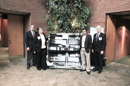
A prototype all-composite underbody with key members of the USCAR underbody team (left to right): Hannes Fuchs, Multimatic Engineering Services; ACC project lead Libby Berger, General Motors R&D; Bhavesh Shah, General Motors Advanced Body; and Charles Knakal, USCAR. Source: SPE ACCE/Photo: Pam & Mike Brady
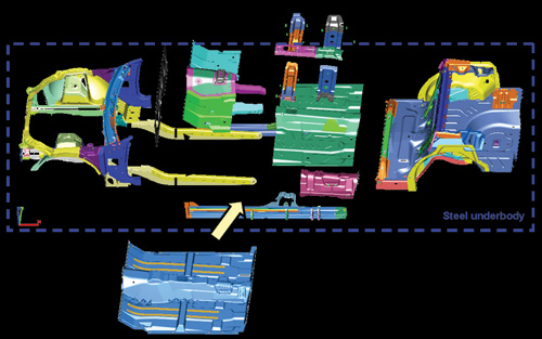
USCAR’s single-piece, structural composite underbody (lower image) replaces 14+ steel stampings and fasteners (upper image) while maintaining or improving performance and safety, and reducing weight, at an acceptable increase in cost. Source: USCAR


For five years, members of the Automotive Composites Consortium (ACC) of the United States Council for Automotive Research LLC (USCAR, Southfield, Mich.) have designed, fabricated and assembled and are now testing a prototype composite underbody for a full-size, rear-wheel-drive passenger car. USCAR is maintained for precompetitive R&D by Michigan-based U.S. auto OEMs General Motors Co. (Detroit), Ford Motor Co. (Dearborn) and Chrysler Group LLC (Auburn Hills). It often partners, as in this case, with the U.S. Department of Energy. The ACC’s underbody team includes Multimatic Engineering (Markham, Ontario, Canada, and Livonia, Mich.), which conducted the engineering and later the assembly build and testing, and Continental Structural Plastics (Troy, Mich.), which compounded the materials.
As part of the ACC’s larger Focal Project 4 (FP4), in which two groups are tasked with developing structural automotive composites, the underbody team’s primary mission was to develop analytical and manufacturing methods and data that would enable any ACC member company to implement lightweight, cost-effective structural composite applications (e.g., the underbody) in high-volume production vehicles.


Expectations were high. The part would function structurally and carry crash loads, with performance equal or superior to that of typical steel North American vehicle underbodies. The team would accomplish this feat while reducing overall mass and meeting all government/industry requirements, with a part “of acceptable cost.”
The underbody was conceived in three phases. In Phase 1, materials and processes were evaluated, and preliminary design work was done. During Phase 2, the team refined the design, conducted extensive analysis, examined methods of attaching the part to the steel body-in-white (BIW), built tooling, and validated materials, processes and analytical methods/assumptions. In Phase 3, the underbody was molded, assembled with a steel frame that represents the BIW mating structure and, testing was initiated.
Phase 1: Consolidate, integrate, analyze
The team compared compression molded sheet molding compound (SMC), long-fiber thermoplastic (LFT) and long-fiber injection (LFI) polyurethane plus several material subtypes. Based on program requirements and the technical cost model, the team decided to use a multilayer, glass-fabric/vinyl-ester SMC with low-density SMC cores and selective use of chopped-fiber SMC to fill thin ribs around the transmission tunnel. Compression molding of fabric/SMC is similar to that of conventional chopped glass/SMC except that charge layup patterns approach 100 percent coverage because the fabric prepreg can’t flow the way chopped glass/SMC does.
In parallel, Multimatic developed a preliminary design in which a single molded composite part — spanning the distance between the vehicle’s firewall and rear seat and from doorsill to doorsill, and with a central transmission tunnel 13 inches/33 cm high — replaced 14 steel components and portions of four others and also eliminated the fasteners. The initial CAE analysis indicated that the toughest crash scenarios would be the Euro NCAP/IIHS 40 mph/64 kmh Frontal Offset Deformable Barrier (ODB) followed by the Euro NCAP 35 mph/56 kmh Full-Frontal Impact load cases. Therefore, a [45/0/-45/90/-45/0/45] layup was selected with a bias to 45°, since the ODB load case was the most severe. Because the part is integral to the vehicle structure, durability and impact load inputs are complex. Conducting simple component-level tests to validate the design would be difficult and potentially unrepresentative of actual loads and stresses.
Phase 2: Refine, combine, validate
As the material models and design were refined in Phase 2, it was important to develop a technique to join the composite underbody to the predominantly steel passenger compartment of the BIW. The method selected — weld bonding — involves the use of a steel doubler strip for the outer layer, with the underbody edge in the middle and the vehicle’s steel structure as the other outer layer. Holes are laser cut in the composite part at predefined locations along its edge (compression molding cannot produce a true through-hole), and the doubler strip features dimples that line up with these holes. A two-part epoxy adhesive from Auburn Hills-based Dow Automotive Systems is applied to the composite, which is then positioned between the two steel layers, with the convex side of the doubler strip’s dimples penetrating through the holes in the composite so they touch the steel vehicle structure. The doubler strip is then spot welded to the steel structure at each dimple location, and the assembled part is placed in an oven to cure the adhesive and fixture the welds. Although the adhesive bond is the primary joint, the spot welds help fixture the part and reduce adhesive peel stresses.
Because the composite underbody would represent a radical change in North American vehicle assembly processes, the team worked on technical cost models for both component manufacture and vehicle assembly, which showed no assembly cost increase and a reasonable jump in manufacturing cost. They also put together a hypothetical work flow that demonstrated how this assembly could be incorporated within a generic auto manufacturing facility. Further, the University of Massachusetts-Lowell (Lowell, Mass.) was engaged to develop a fabric drape model to simulate compression molding of the fabric/SMC material. The model helped the team soften radii and other features against which the fabric preform would have trouble conforming or that could otherwise lead to strand tensile failures during molding. The team also looked for a robust nondestructive evaluation method that would ensure the structural integrity of the composite underbody during normal usage and after low-energy/low-speed crash events, yet be cost-effective and simple enough for collision repair shops to use. Vibrothermography (which uses ultrasonic energy to excite a sample plus an infrared camera to view frictional heating that can indicate delamination) was found to be an excellent method in a research environment, but the group is still evaluating ultraviolet dye penetrants and other methods.
Phase 3: Preform, mold, mate
In Phase 3, the team developed preform blanks and a molding buck, fabricated the part, installed it in the steel frame and is still testing the underbody to correlate analytical results with experimental results. When the CAD model was released to Century Tool & Gage (Fenton, Mich.) to produce tooling, the design’s mass was predicted to be ~26 percent less than the baseline steel design — an 11 kg/25 lb savings. To date, molded parts are somewhat thicker and heavier than predicted, due to the prototype nature of the materials and process. This complex part features up to 13 layers of fabric SMC in 60 pieces, plus several layers of chopped SMC. Cure takes three minutes at 150°C/302°F under 2,300 tons of pressure.


.jpg;maxWidth=300;quality=90;format=webp)


Related Content

Materials & Processes: Tooling for composites
Composite parts are formed in molds, also known as tools. Tools can be made from virtually any material. The material type, shape and complexity depend upon the part and length of production run. Here's a short summary of the issues involved in electing and making tools.
Read More
Materials & Processes: Fabrication methods
There are numerous methods for fabricating composite components. Selection of a method for a particular part, therefore, will depend on the materials, the part design and end-use or application. Here's a guide to selection.
Read More
Scott Bader ATC begins Crestabond MMA structural adhesive production
Scott Bader’s Drummondville, Canada, facility has begun manufacturing and supplying composites-applicable adhesives to its North American customers.
Read More
Epoxy-based structural film adhesive intended for aerospace, MRO
CAMX 2023: Park Aerospace is presenting its new aerospace-grade film adhesive material Aeroadhere FAE-350-1, in addition to other product offerings intended for aerospace, defense and spacecraft.
Read MoreRead Next

Composites end markets: Energy (2024)
Composites are used widely in oil/gas, wind and other renewable energy applications. Despite market challenges, growth potential and innovation for composites continue.
Read More
From the CW Archives: The tale of the thermoplastic cryotank
In 2006, guest columnist Bob Hartunian related the story of his efforts two decades prior, while at McDonnell Douglas, to develop a thermoplastic composite crytank for hydrogen storage. He learned a lot of lessons.
Read More
CW’s 2024 Top Shops survey offers new approach to benchmarking
Respondents that complete the survey by April 30, 2024, have the chance to be recognized as an honoree.
Read More