
Articulated composite booms extend reach of concrete-pumping arms
A 25% weight reduction vs. legacy steel yields economics that justify upfront cost of carbon fiber.

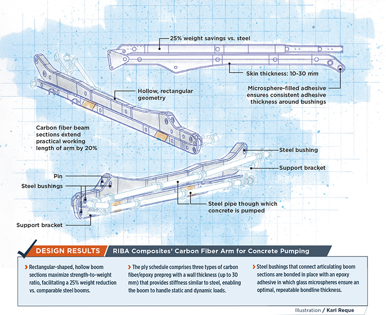
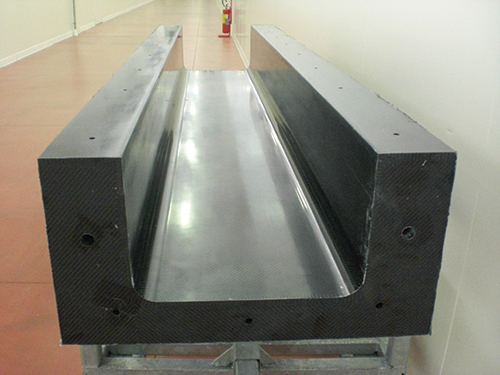
RIBA Composites’ Carbon Fiber Arm for Concrete Pumping. Illustration: Karl Reque
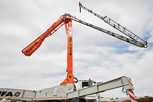
Carbon fiber booms co-developed by Italian construction equipment manufacturer Centro Italiano Forniture Alberghiere Srl (CIFA, Lomazzo) and composites fabricator RIBA Composites Srl (Faenza) replace steel in the final sections of the mechanical arms mounted on trucks like the one in the next photo in this series, to help place pumped concrete in hard-to-reach locations. Source: RIBA Composites
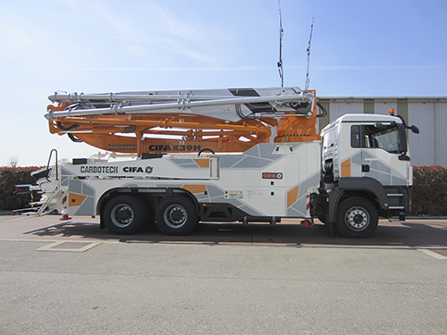
Carbon fiber booms replace steel in the final sections of the mechanical arms mounted on trucks like the one and also on trailers. Source: RIBA Composites
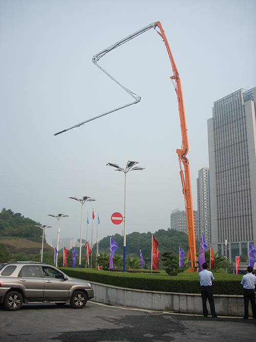
At 101m, this is the world’s longest concrete pumping arm (a certified Guinness Book of World Records awardee). The final 50m of the arm (colored gray) is assembled from three composite booms molded by RIBA Composites. The longest boom, at 14m, weighed ~1000 kg, including 650 kg of carbon fiber, and was cured in a single autoclave cycle. Source: RIBA Composites
Three types of carbon fiber prepreg are layed up in female molds, two tools (lower, pictured here, and a matched upper tool) per boom section. Source: RIBA Composites
Here an assembled mold and completed layup are shown bagged internally and externally and ready for cure in an autoclave. Source: RIBA Composites


Design results:
- Rectangular-shaped, hollow boom sections maximize strength-to-weight ratio, facilitating a 25% weight reduction vs. comparable steel booms.
- The ply schedule comprises three types of carbon fiber/epoxy prepreg with a wall thickness (up to 30 mm) that provides stiffness similar to steel, enabling the boom to handle static and dynamic loads.
- Steel bushings that connect articulating boom sections are bonded in place with an epoxy adhesive in which glass microspheres ensure an optimal, repeatable bondline thickness.
As the use of composites has expanded over the past 70 years, one of their many benefits has consistently driven innovation: Composites enable manufacturers to design and build parts with the strength and stiffness of conventional materials but at significantly reduced weight. Such efforts have captured the “low-hanging fruit,” to much applause, in huge markets — aerospace, boatbuilding and wind energy come to mind. No less important, however, are efforts by pioneers in niche applications that demonstrate, with little fanfare, the unlimited potential of the technology.


Prime examples are Italian construction equipment manufacturer Centro Italiano Forniture Alberghiere Srl (CIFA, Lomazzo) and composites fabricator RIBA Composites Srl (Faenza). To- gether they have developed carbon fiber composite booms for concrete-pumping machines. In full commercial production since 2011, the booms can be made in a variety of lengths.
Cascading savings
Mounted on trucks or trailers, concrete-pumping systems typically are fitted with articulating arms made of steel, which support the steel tubing through which concrete is pumped. Depending on site accessibility and the height of the concrete pour, the arm’s end might extend hundreds of feet from the pump location. The greater the distance, the greater the moment of downward force that acts on the arm and must be counter-balanced at the truck or trailer.
RIBA’s carbon fiber booms replace the outermost segments of the arm where that force is greatest (see photo, at left) and realize section weight savings on the order of 25%. This opens the way to other benefits that justify the nominally higher cost of the carbon fiber. “The reduced weight means a smaller counterweight is needed,” says Andrea Bedeschi, RIBA’s general manager. In turn, the arm can be operated with smaller hydraulic cylinders and the entire system can be carried by a smaller, lighter truck or trailer, reducing initial investment and improving fuel economy. Additionally, a carbon boom extends the work length of the arm by as much as 20%. Finally, because scrutiny of and restrictions on truck weight are increasing, operators with oversized loads can face expensive surcharge levies or, in some countries, find themselves banned from roads. The lure of these potential benefits was the motivation for tackling the challenge of designing, making and selling a completely new part for an entirely new application.
Leveraging know-how
The chances for a commercially successful outcome to this essentially blank-slate project were bolstered by RIBA’s experience in designing and building carbon fiber spars and masts for sailboats. “We are experts in building long tube sections,” Bedeschi says. “The way we design and manufacture these booms is basically by applying the same principles for carbon fiber masts.”
To prove project feasibility, RIBA conducted FEA modeling studies, using MSC Software’s (Newport Beach, Calif.) MSC Nastran. According to Bedeschi, the effort entailed three key technical challenges, one related to design, another related to manufacturing and a third with an impact on long-term operation. A fourth challenge, market acceptance of a new paradigm in the construction industry, was mitigated, in part, by partner CIFA’s buy-in to the project once feasibility studies were completed and costs, including ROIs, were evaluated.
The key to project feasibility was designing a laminate structure with stiffness similar to the steel benchmark, a daunting challenge given that the latter has a Young’s modulus of about 207 GPa, vs. roughly 120 GPa for a PAN-based carbon/epoxy unidirectional laminate layer of the same thickness. In crude terms, this 40% stiffness deficit could be overcome by building up laminate thickness, but that would also build cost. FEA simulation enabled engineers to simultaneously assess laminate structures that would meet the stiffness criteria and explore the most cost-effective means to construct those laminates.
Each boom is subject to two primary loads: Static loads from the weight of the boom, the attached steel tubing and the concrete pumped through it; and dynamic loads generated in boom joints as the arm is moved. Simulation of both revealed that optimum boom strength-to-weight would be achieved by a hollow, rectangular geometry and a ply schedule comprising unidirectional 24K carbon fiber tape (with fibers oriented along the isostatic lines or stress trajectories), ±45° biaxial 24K carbon fiber prepreg, and ±90° woven 24K carbon fiber prepreg built up to a nominal wall thickness ranging from 10 mm up to 30 mm in high-load areas. All materials are impregnated with a toughened epoxy supplied by Saati (Legnano, Italy). The UD tapes, which account for ~50% of the laminate thickness, play a role in optimizing the structure’s bending stiffness. The ±45° biaxial prepreg and ±90° woven prepreg each comprise ~25% of the total thickness, enhancing the structure’s resistance to torque and damage respectively. RIBA sources its fabric, prepreg and fibers variously from Saati, G. Angeloni Srl (Venice, Italy), Toray Carbon Fibers Europe (Paris, France), Toho Tenax Europe GmbH (Wuppertal, Germany) and Mitsubishi Rayon Co. Ltd. (Tokyo, Japan).
The FEA study also focused on joint construction, which would require some type of pinned connection. “There was an engineering concern about this feature of the boom design because of the reduced load-bearing capacity of composites compared to metal and the potential to damage the epoxy matrix in the joint area,” Bedeschi recalls. Analysis suggested that 50-60-mm metal bushings would work if a way could be found to properly and reliably bond the metal components to the carbon/epoxy composite. Engineers devised a two-fold solution. First, to bond bushings to carbon/epoxy laminates, RIBA used Hysol epoxy adhesive, supplied by Henkel (Düsseldorf, Germany), in which the adhesive layer’s bondline is controlled by glass microspheres, the diameter of which ensures an optimum, repeatable adhesive thickness, maximizing polymerization and shear strength at the bond. Second, the laminate at the joint interface is constructed of ±45° fabric, which reportedly reduces stress in the laminate at the joint surface. Extensive testing of laminate specimens was conducted in parallel with FEA to ensure that actual mechanical properties (in particular, stiffness) correlated with the simulations.
After testing validated the computer models, RIBA received approval from CIFA to build the first commercial boom sections for a concrete-pumping machine. They replaced the final two articulating sections — roughly half the total length of a 45m mechanical arm. Each section is about 11m in length. They do not replace the initial steel sections of the arm with composites because the cost vs. benefit tradeoff favors metals. Building the entire arm with composites would be cost-prohibitive.
Boom sections are molded in female molds. During layup, overlaps of 25.4 mm to 38 mm are created between adjacent plies of prepreg, per aerospace practice. The molds are joined at the laminate overlaps, creating a hollow tube. After layup, the molds are bagged internally and externally, and the bag materials are joined at the mold’s open ends to form a single bag (see photos, at left). During autoclave cure (at 6 bar), the vacuum pulled on the bag combined with the external pressure applied by the autoclave ensures optimal consolidation and strength-to-weight ratio in the laminate, yet avoids pressure-related deformation or alteration of the mold shape. “The pressure is acting on all the surface of the bag, internally and externally,” says Deschi. “In this way we squeeze the plies without affecting the mold.”
A final challenge was curing parts with walls as thick as 30 mm. Epoxy undergoes a robust exothermic reaction — the thicker the laminate, the higher the temperature. The risk is uneven heating of the mold and laminate layers, resulting in material degradation at the center of the laminate’s through-thickness. Using a theoretical autocatalytic model, engineers predicted cure behavior as a function of temperature and devised a cure cycle with a cure temperature of 130°C and dwell steps that avoided exothermic peaks and resulted in homogeneous heating of the mold and laminate. Cycle duration, including cool down, is ~18 hours.
After cure, the demolded boom is CNC-machined on a 5-axis system, bushings are bonded into place and each section is inspected using a phased-array ultrasonic NDT system.
Since making its first 22m boom section set, RIBA’s line of booms for concrete-pumping equipment has steadily expanded. The company now makes 10 different carbon booms for concrete-pumpers with arms ranging from 25m to 101m. Widths of booms can vary from 15 to 45 cm.
Last year, RIBA produced booms for 110 arms— about 250 individual booms, and Bedeschi expects a 10% increase in sales during 2015. That the booms have quickly made inroads into an inherently conservative industry is a testament to their highly functional design and benefits.


.jpg;maxWidth=300;quality=90;format=webp)


Related Content

CAMX 2022 exhibit preview: Innerspec Technologies
Taurus and Camus 3D ultrasonic inspection systems provide automated and semi-automated solutions for composite aerospace components.
Read More
UTComp authors bulletin on fitness-for-service assessment of FRP
Welding Research Council (WRC) Bulletin 601 provides technical background and validation for quantitative nondestructive testing methodology for FRP composite equipment.
Read More
Loop Technology develops robotic arm for wing box inspection
Part of an R&D project with Spirit AeroSystems, the seven-axis Bravura robotic arm automates inspection and sealing within small spaces like aircraft wing boxes.
Read More
Nondestructive inspection methods available to composites manufacturers
An overview of composite laminate inspection techniques ranging from manual testing methods to more advanced, noncontact options.
Read MoreRead Next

Composites end markets: Energy (2024)
Composites are used widely in oil/gas, wind and other renewable energy applications. Despite market challenges, growth potential and innovation for composites continue.
Read More
From the CW Archives: The tale of the thermoplastic cryotank
In 2006, guest columnist Bob Hartunian related the story of his efforts two decades prior, while at McDonnell Douglas, to develop a thermoplastic composite crytank for hydrogen storage. He learned a lot of lessons.
Read More
CW’s 2024 Top Shops survey offers new approach to benchmarking
Respondents that complete the survey by April 30, 2024, have the chance to be recognized as an honoree.
Read More