
Albany Engineered Composites: Weaving the Future in 3-D
This 3-D weaver turned composite component supplier pursues a future in 3-D structures through continuous technology development.

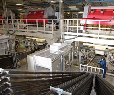
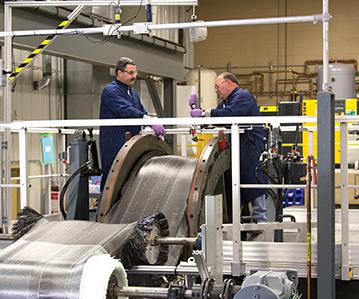
Thousands of carbon fiber warp ends enter a Jacquard loom of the type that gave Albany Engineered Composites’ (AEC, Rochester, N.H.) parent company its leg up on the papermaking industry (see sidebar at end of main article). AEC has added to weaving a commitment to manufacture of finished parts — such as the fan blade and fan case (next two photos) for the next-generation LEAP jet engine (third photo down). Source: Albany International
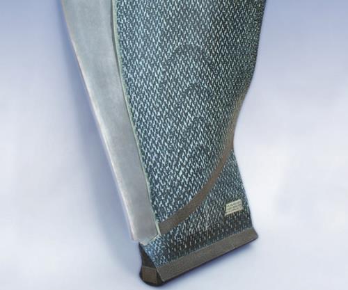
LEAP fan blade. Source: Albany International
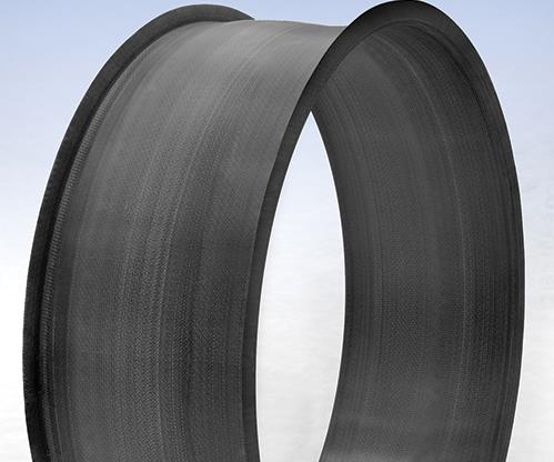
LEAP fan case. Source: Albany International
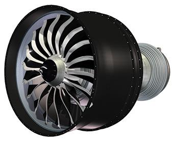
The LEAP jet engine. Source: Safran/Snecma
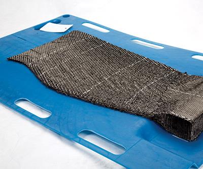
Process steps for fan-blade development in ASC’s PDC include 3-D weaving of the preform (pictured here); forming and drying of the preform; placement of the shaped preform into the RTM tool (next photo); tool insertion into the press and injection of heated resin, followed by cure; demold of the still hot part (thrid photo down) and final finishing operations. Source: Albany International Corp.
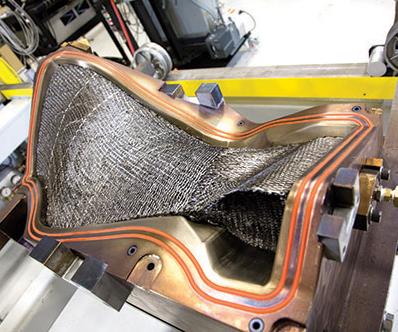
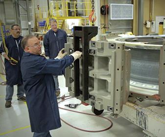
The shaped preform is paced into the RTM tool. Source: Albany International Corp.
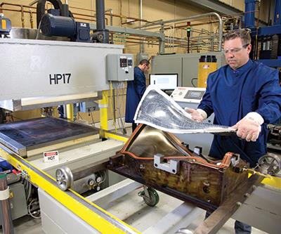
The still hot part is demolded prior to finishing operations. Source: Albany International Corp.
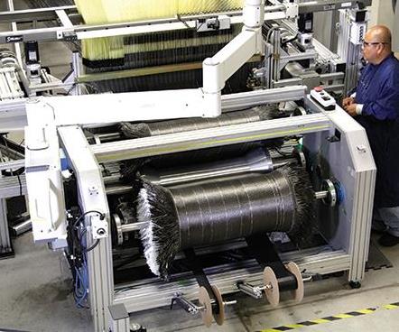
The 3-D fabric for the LEAP fan case is wound onto a take-up mandrel as it is produced (left). It is then used in the winding process, see next two photos). Source: Albany International
The shaped fabric is applied to the inner mandrel of the RTM tools (see next photo. Source: Albany International
Outer tools are applied and the part is placed into an oven where heated resin is injected via the RTM tooling and cure completed ( image shows demolding). Source: Albany International

Using internally developed design tools, AEC can perform process simulations as well as predict the performance of a finished 3-D composite structure. Capabilities include forming simulation and prediction of strength, stiffness and performance vs. failure criteria. Source: Albany International
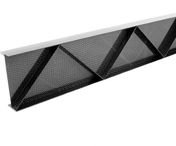
AEC is working with aerospace OEMs to design 3-D aerostructures, targeting applications for which conventional 2-D composites do not meet out-of-plane strength and/or damage tolerance requirements. These include, for example, this truss beam for floor support (see next two photos for other examples). Source: Albany International
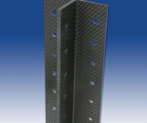
Target applications for 3-D aerostructures also include rib posts such as this for as wing leading edge stiffeners. Source: Albany International
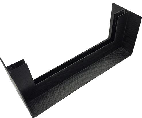
Target applications for 3-D aerostructures also include Pi-joint corner brackets, such as this one. Source: Albany Internaitonal
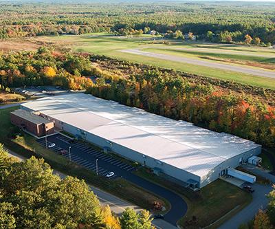
The first of three overhead shots of AEC’s New Hampshire complex: Building 1. Source: Albany International
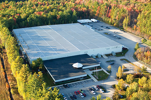
An overhead shot of AEC’s Building 2. Source: Albany International
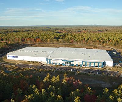
An overhead shot of AEC’s Plant 1, in New Hampshire. Source: Albany International


Overnight success stories are, typically, decades in the making. Albany Engineered Composites Inc. (AEC, Rochester, N.H.) is a classic case in point: Its recent selection by Paris, France-based Safran as a partner in the manufacture of 3-D woven composite fan-module components for the LEAP commercial aircraft jet engine was a huge achievement. No less noteworthy, however, is the story behind the news. HPC recently toured the company’s New Hampshire facilities and gained insight into how AEC’s history of technology development has enabled its partnership with Safran, its transformation from textiles to parts manufacturing, and its confidence in the future of 3-D composite structures.


Fifty years of innovation
AEC’s story dates back to 1895, when parent company Albany International was founded in its namesake city, Albany, N.Y. A textile weaver, the company became a market leader in production of fabrics used in papermaking.
A defining moment in the AEC story was Albany International’s purchase in 1998 of Techniweave Inc. (Rochester, N.H.). Like other “specialty weavers” at that time, Techniweave produced fabrics using carbon, ceramic, aramid and other technical fibers. Significantly, its development programs focused on complex, three-dimensional (3-D) net-shape preforms for composite structures, such as square tubes with integrated branch connections and one-piece egg crate-type stiffeners. (Foreshadowing AEC’s future, a competitor, Textile Technologies Inc., Philadelphia, Pa., had already developed a fan blade-shaped preform.)
Albany International saw the value in 3-D preforms. Similar to its papermaking fabrics, preform layers were joined by layer-to-layer interlocking fibers, making the structure’s through-thickness properties more like its in-plane properties, and eliminating the risk of delamination associated with the discrete layers of fabric in conventional composites. But unlocking their potential would require improved speed and lower cost in the weaving process, without losing quality or process control — exactly the brand of expertise Albany had acquired during decades of weaving 3-D fabrics using two-dimensional (2-D) looms (see “Albany International: Multilayer to multidimensional weaving,” at the end of this article or click on its title under "Editor's Picks" at top right).
Elsewhere, two other defining events took place. In the 1990s, GE Aircraft Engines (now GE Aviation, Cincinnati, Ohio,) developed the first all-composite commercial turbofan blade used in the GE90 engine for The Boeing Co.’s (Chicago, Ill.) 777 wide-body aircraft. GE proceeded with two large composite fan-blade applications in the GEnx engines for the Boeing 787 and 747-8. (These blades are still in production at CFAN, a 50/50 joint venture between GE and Snecma in San Marcos, Texas.)
In early 2000, engine manufacturer Snecma (Courcouronnes, France) resumed its R&D into 3-D woven aircraft-engine composites. It was at this time that Snecma and Albany International Techniweave began codevelopment of 3-D woven composite fan blade technology, demonstrating its viability in a GE90 configuration. Work then shifted to smaller CFM56-sized blades (to replace monolithic titanium) where the 3-D woven composite became an enabling technology for next-generation performance improvements in the new LEAP engine, developed by CFM International (Cincinnati, Ohio and Evry, France). Snecma merged with Paris-based Sagem SA in 2005 to form Safran.
The following year was the tipping point for Albany International Techniweave. It acquired two companies: Texas Composites Inc. (TCI, Boerne, Texas), a developer and manufacturer of engineered composites using resin transfer molding (RTM), 2-D textiles and braids; and Aztex Inc. (Waltham, Mass.), whose Z-fiber technology had cut thousands of fasteners and almost $100,000 in assembly costs from the F/A-18 and other military aircraft programs.
The acquired companies were merged and renamed Albany Engineered Composites. AEC then entered into an exclusive relationship with Safran/Snecma to develop and commercialize advanced 3-D woven composite components for aircraft engines and landing gear.
With 19 plants in 11 countries, $760 million in revenue and 4,000 employees, Albany International Corp. (Rochester, N.H.) today is not a small company. Yet its stature is diminutive in the field on which it now plays. Safran, for example, is a global conglomerate of 10 companies and more than 50,000 employees with annual revenue totaling €13.5 billion. Using its financial strength as the leading supplier of technical textiles to the paper industry, Albany International has invested in a vision for future growth: To become a leading Tier 2 supplier of advanced composite components to the aerospace industry, using highly engineered textile reinforcements designed and assembled by AEC.
“We are leveraging 50 years of innovation in engineered textiles and process automation coupled with a legacy of technology investment by our parent corporation,” says Brian Coffenberry, AEC’s senior VP of business development, research & technology. “Continuing that tradition, AEC’s commitment to R&D is substantial — nearly $13 million out of approximately $80 million in revenue for 2013.” The CFM LEAP engine program is a prime example: for nearly 10 years, AEC invested in R&D and capital equipment to support Snecma’s fan blade development program, prior to inclusion of the blade and fan case into the LEAP design. “We faced challenges in the first parts we wove and molded,” admits Coffenberry, “and have had to make refinements to the process in order to meet Safran’s stringent requirements.” But, he continues, “We worked together closely with Snecma using design rules that recognized current process capabilities and limitations for manufacturability, while AEC recognized areas for process improvement — a successful collaboration that continues today.” For example, a 3-D blade reinforced with IM7 48K tow is less expensive to weave, but is less tailorable, while a smaller tow size is woven more slowly but is more tailorable to localized load conditions. “Snecma understood this early in blade development and, therefore, established design rules that limited how fast the thickness of the blade could be tailored (e.g., ply drops per inch) to the loading conditions.”
AEC operations
The dedication shows in New Hampshire. AEC occupies three buildings in a large industrial park outside of Rochester, as well as the original 135,000-ft2 (12,542m2) TCI facility in Boerne, Texas (see Table 1, p. 59).
The production space in Building 1 is dominated by a long line of massive looms. Each loom’s Jacquard mechanism reaches to the ceiling, supported on its own steel platform from which the iconic pyramid of converging harness cords descends, each cord having a heddle eye through which a single warp end is drawn. Adjacent to these, a number of smaller jacquard looms make a variety of preforms for other programs. During HPC’s visit, the large looms — which can handle as many as 8,448 warp ends of various fiber types and sizes — were turning out preforms for blades, fan cases and landing-gear components.
LEAP fan blade preforms use Hexcel (Stamford, Conn.) IM7 48K fiber — four 12K tows lightly twisted by Concordia Fibers (Coventry, R.I.) — which reduces cost.
“If you drive tow size down,” Coffenberry explains, “it drives the number of warp ends up, which increases set-up time as well as the number of picks (weft insertions), lengthening weave time.” He noted that AEC uses 3-D textile and preform modeling software to optimize its selection and combination of fiber types and tow sizes to achieve desired load handling capability and geometry.
Prototyping production processes
In Building 2, HPC viewed the Albany Safran Composites (ASC) product development center (PDC). Here, AEC and Safran (through ASC) develop the RTM and ancillary processes used for each new part, characterizing each before it goes into full production in Plant 1 and then ramps toward production rates that, for LEAP, will reach 1,800 shipsets (32,400 blades) per year by 2019.
“The PDC space can be reconfigured,” Coffenberry points out, “as future parts for the LEAP and other Safran applications are selected for transition into product development and production.”
The PDC was the stage for the development of the final processing steps for the fan blade (pictured on left). Cytec (Woodland Park, N.J.) single-component toughened epoxy resin was chosen for use in blades, case, spacers and platforms. For the fan case preforms, 3-D weaving and contour weaving are combined to produce a finished barrel with flanges on each end, using basically 0˚ and 90˚ inputs. The 3-D fabric is wound on a take-up mandrel as it is woven, and then used in a winding process to shape the inner fabric on the inner mandrel of the RTM tool. Outer tool segments are assembled to the mandrel and the preform and tool are placed in an oven where heated resin is injected and cure completed (see photos at left).
3-D composite production
At the time of HPC’s tour (October 2013), LEAP Plant 1 had just received its certificate of occupancy, and its looms, RTM presses and other blade-making devices were in place. Fan-case equipment was soon to follow and low-rate production was scheduled to start in 2014. The plant’s enormous, mostly open, floor plan features walls only where needed to enclose waterjet-cutting, CNC-machining and mold-cleaning operations. According to Coffenberry, AEC will do everything from weaving through cure. Safran will handle final machining, painting, balancing and nondestructive testing (NDT). “There are no walls between the AEC and Safran work areas,” he adds.
The workflow is designed according to lean manufacturing practice: Raw material will enter AEC’s end of the building and proceed through a streamlined linear layout, with finished products exiting the Safran end of the plant. Because cranes cause bottlenecks, the plant design eliminated them where possible to shorten throughput time. Production progressively moves through five work cells: winding, weaving, premold, injection/cure and mold cleaning (the latter uses dry ice blasting, which was cited as an environmentally friendly alternative to solvents).
Coffenberry said the facility was designed with the LEAP engine’s rate production and expected growth in mind. “We used a conservative design with some built-in redundancies to provide more capacity than strictly required,” he points out. “For example, should there be equipment breakdowns, we have built-in ‘catch-up’ capacity. Once the plant is running at full rate, we will gain efficiency and be able to free-up capacity as new ASC products are ready to be transferred from the PDC for full-scale production.”
Future products from conception to production
The 45,000-ft2 (4,181m2) Research & Technology (R&T) Center, finished in 2013, is currently staffed by 24 engineering specialists and an equal number of technicians. This part of Building 2 is the industrial proving ground where AEC develops new engineered textile and composite products, processes and engineering software, and performs equipment modifications.
“We try it out here before we run it on the floor in a full-scale implementation,” said Coffenberry. “For example, we will try out new loom designs for higher speed.”
Pointing to a large piece of equipment that looked like several different types of looms put together, Coffenberry noted, “This uses four shuttles so we can have four different weft materials.”It also features technology enabling products with a closed fabric edge (uncut) vs. current open (cut) fabric edges, said Coffenberry, noting that AEC is evaluating the device for potential use in manufacturing new products, including airframe substructure applications.
Close by, he points out a fiber placement machine, describing it as “an R&D unit, which we can use for thermoset and thermoplastic fiber placement in addition to through-thickness fiber reinforcement.” He adds, “It is also being considered for dry fiber placement, which is a process we believe may be amenable to our 3-D textiles.”
The next stop was a microcomputed tomography (CT) lab. Akin to medical imaging technology, “we use it to characterize our materials and calibrate and validate our analytical models,” Coffenberry explains. “We use the modeling and testing together to predict and verify performance. We also perform material variability testing here as part of quality assurance.”
Not limited to textile engineering, AEC’s development work extends to RTM, resin infusion and autoclave processing. (The autoclave is supplied by ACS Process Systems in Valencia, Calif.). HPC viewed AEC’s large oven, from Wisconsin Oven Corp. (East Troy, Wis.), which can be divided into two parts with separate temperature control up to 350°F/177°C. Behind it stood AEC’s new and largest (440-ton) press, supplied by Pinette Emidecau USA (Troy, Mich.).
Next was a station room where variations of X-Cor and K-Cor structural foam products are developed for use in sandwich composites. These textile-based core materials are made via fiber insertion technology that AEC acquired with Aztex — the materials feature a three-dimensional truss network of pultruded carbon-fiber/epoxy rods in the z-direction. “We want to sell not just core but the whole part, engineered to meet specific requirements,” says Coffenberry.
Building the future on strengths
Using internally developed design tools, the R&T Center can perform process simulations and quickly predict the performance of a finished 3-D composite structure. “We have developed a fairly sophisticated capability that allows us to determine the as-formed fiber architecture very closely,” said Coffenberry. “We can calibrate structural performance predictions on strength vs. stiffness, and can also look at different failure criteria to see which predicts performance best.”
Notably, simulations reduce the customer’s cost and the time required for development and certification. “It once took months to design iterations on a fan blade,” says Coffenberry. “We now complete design iterations on a part of similar complexity in days.” R&T product development also tracks generic structural features — such as corners — during forming to gain an understanding of how these are affected and better predict their performance. “For example, we can compare relative performance using 2-D textiles vs. noncrimp fabrics vs. 3-D preforms,” he said, “From this, we can feed material property maps to customers for use in their finite element models so they can design a part using 3-D woven reinforcement, or we can design the 3-D composite structure for them.”
AEC has several such programs ongoing with aerospace OEMs, focusing on structures where conventional 2-D composites do not have the required out-of-plane strength and/or damage tolerance. One example is airframe substructure components. Coffenberry showed a variety of samples, including sine-wave floor beams that feature sine wave-shaped Pi preforms. (Read about Pi preform technology in “Wind blades: Pi preforms increase shear web failure load,” under "Editor's Picks").
Although Pi preforms for airframe applications aren’t unique to AEC, Coffenberry says AEC’s approach to them is: “Rather than using a one-size-fits-all approach, we engineer the Pi preforms to the specific application requirements and extend the technology to look at shaped Pi preforms using Hexcel’s stretch-broken carbon fiber, as well as lengthwise-tailored flange, web and clevis dimensional characteristics.”
AEC, through ASC, will work with Safran on a variety of new LEAP and next-gen engine applications (e.g., nacelles, thrust reversers) and on landing gear. One example is Snecma’s open-rotor engine, targeting a 30 percent reduction in fuel consumption vs. today’s narrow body turbofans and aiming for a 2030 entry into service. The counter-rotating propeller is used at the rear of the plane with blades more than twice the length of those in LEAP and open to the atmosphere. “We are applying LEAP-comparable technology, but modified to this design,” Coffenberry relates.
3-D composites in the hot zone
In addition to its work in polymer matrix composite applications, AEC also is applying its technical know-how to ceramic matrix composites (CMCs), where the 3-D fiber architecture overcomes some of the inherent brittleness of the matrix. AEC has worked for several years with Safran subsidiary Herakles (Le Haillan, France) to develop a CMC low-pressure turbine blade for potential use in future LEAP engine upgrades. AEC is providing complex 3-D woven preforms to Herakles’ facility in Bordeaux, France, for subsequent densification into the final composite.
AEC also has been working with Boeing to provide a CMC substrate for an exhaust nozzle under evaluation in the U.S. Federal Aviation Admin.’s (FAA, Washington D.C.) Continuous Lower Energy Emissions Noise (CLEEN) Program. The nonstructural acoustic CMC sandwich features Nextel fiber from 3M (Minneapolis, Minn.) with an oxide matrix. It has the potential to reduce weight and noise and extend part life vs. current metallic nozzle designs. A CMC exhaust nozzle was successfully tested last year in a full-scale ground-based engine test (see “Ceramic-matrix composites heat up,” under “Editor's Picks”).
Growth beyond aerospace
AEC also sees growth beyond aerospace. Among the new markets AEC has evaluated, automotive is one where its technology might edge out metals and conventional composites. AEC sees potential thanks to the demand for vehicle weight reduction driven by government-mandated fuel efficiency and emission standards. “The same characteristics that make 3-D RTM composite structures attractive for aerospace might offer energy absorption benefits vs. normal laminated composites in automotive structures,” Coffenberry suggests. To demonstrate the advantages of its 3-D composites, AEC has been working on a generic car door side-impact beam, which could offer up to 25 percent weight savings and a significant increase in energy absorption, compared to the baseline design in high-strength steel.


Related Content

Noble Gas Systems 350-bar conformable pressure vessels pass HGV2 standard tests
Conformable tanks with new materials pass technical tests for hydrogen storage, to compete with Type IV pressure vessels using CFRP.
Read MoreRead Next

Wind blades: Pi preforms increase shear web failure load
Easily coinfused structural joint increases ultimate strength and fatigue life, offering solutions for designers as blades get longer and move offshore.
Read More
Wind blades: Pi preforms increase shear web failure load
Easily coinfused structural joint increases ultimate strength and fatigue life, offering solutions for designers as blades get longer and move offshore.
Read More
3-D woven reinforcements update
Suppliers make progress toward reinforcement preforms that exhibit comparable properties in the x, y and z axes.
Read More