
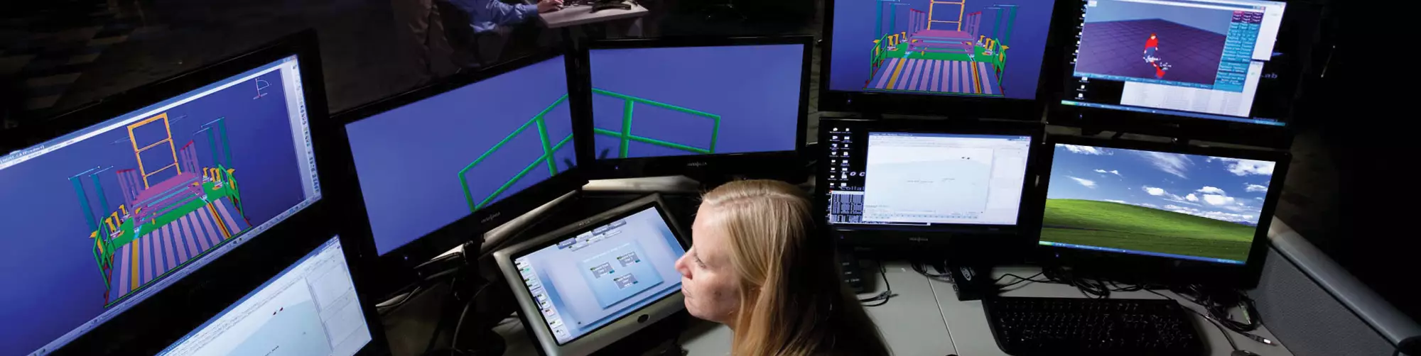


CHIL moves 3D models from monitors to a virtual environment, where engineers can perceive and interact with life-size 3D models. Source | Lockheed Martin
Virtual reality.
It’s a term many associate with the fictional worlds created in movies such as The Matrix and the playgrounds found in today’s sophisticated computer games. Since the early days of CAD, engineering and manufacturing, composites engineers have used sophisticated software to create accurate virtual representations of advanced composites products and technologies. It could even be argued that virtual reality is simply an outgrowth of these virtual technologies that have long serviced the industry.


But what makes virtual reality and associated technologies distinct is the interaction they provide between virtual and actual worlds. Developed to enable filmmakers and video game developers to capture the movements of live actors and insert them into animated film and video formats, virtual reality (VR) applications today can, for example, enable an engineer or technician fitted with strategically placed body sensors to become immersed in a virtual manufacturing environment — perceiving and interacting with life-size, 3D models of prospective machines and systems, future components or assemblies, or become part of a virtual manufacturing floor and move about the environment as digital avatars. In these and other practical ways, composites design and manufacturing engineers have reaped and are more widely reaping many benefits from VR technologies.
The range of VR/AR technologies, their developmental and readiness levels, and their implementation and acceptance in the composites industry, widely vary.
Further, they are developing technologies that mix the virtual and actual manufacturing realms. Admixtures of the virtual and actual provide additional sets of applications. Typically categorized as “augmented reality (AR)” or “mixed reality,” these applications vary in the degree to which virtual and actual elements play a part. On one end of the spectrum, “augmented virtuality” might describe a 3D digital model onto which images and data from an actual component are superimposed, such as actual ply images from an automatic inspection system, showing deviations from the nominal of ply boundaries, fiber orientation and the like. On the other end, an augmented reality application might enable a technician to “see” under-surface laminate damage, accurately located on the actual component, as he or she looks through virtual glasses.
The range of VR/AR technologies, their developmental and readiness levels, and their implementation and acceptance in the composites industry, widely vary. So, too, do the particular areas to which the technologies apply, from advanced virtual prototyping through the entire product lifecycle to maintenance and repair operations.
The benefits that result from these VR/AR leaps include reduced development time, reduced risk, lower manufacturing costs and shorter cycle times.
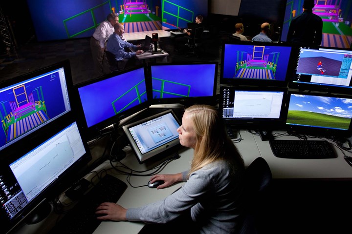
Lockheed Martin’s Collaborative Human Immersive Laboratory enables participants to assess manufacturing floor and equipment plans in a virtual environment before the company invests in the actual shop floor. Source | Lockheed Martin
Immersive product prototyping
Since the advent of computer-based virtual prototyping, composites designers and manufacturers have saved untold development costs and enabled greater part optimization because a part design could be modified without the attendant time and cost penalties of building a new physical prototype. Those early adopters are enjoying even greater advantages as they implement VR prototyping technologies.
Lockheed Martin’s (Bethesda, MD, US) foray into VR technology, which the company is using for prototyping as well as evaluation of manufacturing processes, is housed at its Collaborative Human Immersive Laboratory (CHIL, Denver, CO, US). One of the largest such facilities in the world, CHIL reportedly saves Lockheed Martin more than US$10 million annually in its spaceflight, satellite and solar-array programs, according to the lab’s manager, Darin Bolthouse. Making the investment that much more financially sound, Lockheed Martin has kept costs down at CHIL in part by employing standard consumer devices, such as the Oculus VR (Menlo Park, CA, US) Rift headset.
With computer-based CAD and simulation programs already providing sophisticated graphical representations, Bolthouse believes VR is the logical next step. “We’ve got this wealth of 3D data already out there,” he points out. “The ability to bring that into an immersive VR environment allows our engineers to see that in full scale.”
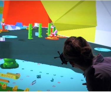
CHIL includes two primary VR approaches, the first of which is used for VR prototyping. Called a CAVE (cave automatic virtual environment), this VR approach uses wall-sized displays to generate full-scale 3D models of components, systems or assemblies that appear to “float” holographically in space as engineers view them through 3D glasses. The 3D images can be rotated and repositioned, giving the engineers the ability to view all aspects from any angle.
Several other VR prototyping applications are employing a virtual reality system from the ESI Group (Paris, France) called IC.IDO. The company describes IC.IDO as a VR solution that combines “high-end visualization and real-time simulation of product behavior in its actual size.” To produce its CAVE, the IC.IDO system includes stereoscopic projection hardware directed at multiple “powerwalls.” Users wear 3D glasses to experience life-size renditions of the prototypes they are developing.
Helmut Dietz, head of digital manufacturing at Bombardier Transportation (Montréal, QC, Canada), reports that the IC.IDO systems his company employs can save up to 70% on prototype costs. CAD data from the company’s CATIA V5 design system feed into the VR system to produce the 3D images for the CAVE. “In the end, we can view the developed vehicle on high-resolution powerwalls — and even touch it,” says Dietz of the IC.IDO experience. “This way, development and installation steps can be accelerated, optimized or done away with entirely.”
Virtually verifying workcell/worker fit
A VR CAVE can be used for virtual interaction not only with prototypes, but also with whole manufacturing and assembly lines, and ESI’s IC.IDO is also being used for these applications. Safran Nacelles (Le Havre, France) applied its 4m-wide by 2.5m-high, two-wall IC.IDO CAVE to evaluate its Airbus A330 nacelle production line. The A330 nacelle features an innovative one-piece composite inner structure. Because engineers could accurately visualize the tooling needed before ordering hardware, Safran engineers reduced the nacelle’s development cycle from 60 to 42 months. Equally as significant as the time savings was the economic value of the VR system, reports Nicolas Lepape, Safran Nacelles’ research and technology project manager for virtual and augmented reality. “The typical cost of creating a virtual reality CAVE is €100,000 to €200,000 – which is equivalent to the average price of one major piece of tooling for a final assembly line,” he points out.
Back at Lockheed Martin’s CHIL facility, in addition to the company’s CAVE, a second VR approach enables engineers, as noted above, to enter and interact with the virtual world by donning an array of body sensors and standing in a motion-capture area. The advantage here is the ability to directly check, for example, something as simple — but as time- and cost-critical — as whether a fastener position can actually be reached by an installer within an assembly. By analyzing design and manufacturing processes in the virtual world before building physical facilities and components, CHIL enables engineers and technicians to analyze, evaluate and modify systems and processes when the expenditure of time and the financial investment for the latter will be at its lowest. Additionally, VR evaluation enables Lockheed Martin to easily and inexpensively maximize worker safety and productivity by developing ergonomically sound manufacturing cells and equipment.
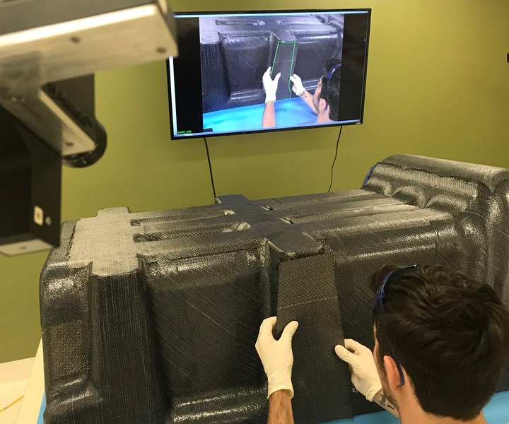
Anaglyph’s PlyMatch system displays the actual layup overlayed with virtual guidance. A technician views the layup and guidance on a monitor as he positions the next ply. Source | Systima Technologies
CHIL evaluates all stages of the product development lifecycle for Lockheed Martin systems, so application to composite components is part and parcel of the broader program. One recent CHIL evaluation was performed on the main propulsion fuel tank for the company’s new LM 2100-series satellite bus, which is a major redesign of the company’s proven A 2100-series.
“We used CHIL to make sure we could install the tank,” explains Andrew Bushell, senior manufacturing engineer at the company’s John C. Stennis Space Center in Mississippi, US. The 117 cm-diameter metal tank with composites overwrap plays a critical role in meeting goals of decreased production time and costs for the new series.
“There were questions about reach, fit and line of sight,” Bushell recalls. “It was very helpful to get a feel, ergonomically, of what we were up against. We have drawings and dimensions, but you don’t have a true appreciation until you have it in virtual reality.” Bushell notes, for example, that the VR motion-capture system was used to test whether a technician could reach a high-torque bolt and, with arm extended, operate the torque wrench safely and effectively. Bushell adds that the composite overwrap required special attention during the VR simulation. “We looked at all our surface contacts and made sure there was no direct contact with the composite overwrap, to protect it from scratching.” (In an interesting sidelight, since the LM 2100 tank was moved into production using conventional manufacturing methods, Lockheed Martin also has qualified a 3D-printed version of the tank for space flight.)
Lockheed is currently using CHIL to develop AR applications for its space programs, and the facility has hosted investigators from other business units to perform evaluations and to collaborate on VR/AR advancements and applications across the Lockheed Martin technology spectrum.
An application of VR manufacturing floor design at the Airbus Broughton, UK facility assists engineers there in the validation of composites manufacturing methods and process improvements required for the A350 XWB aircraft. Its wing is built in a horizontal, rather than the more common vertical, configuration. Airbus wanted to prove it could build the wing this way before investing in the tooling. “They wanted to simulate the whole assembly process in a virtual environment,” recalls Julian Ford, business development manager at VR supplier Virtalis (Manchester, UK).
Airbus chose the Virtalis ActiveWorks VR suite for this application. Geoff Tantum, then the engineering group leader for simulation at Airbus UK, selected ActiveWorks in part because of its ability to interact seamlessly with the facility’s Dassault Systèmes (Vélizy-Villacoublay, France) product lifecycle management (PLM) software. “We wanted a system that would take our CATIA and DELMIA PLM data and turn it into a 3D VR model automatically, without any need for translation,” he recalls.
Virtalis demonstrated that its system could perform as required before Airbus invested in it. Unfortunately, Ford says, Airbus discontinued the application after Tantum left the company — an example of the obstacles VR technology may continue to face before more composites industry personnel are familiar and comfortable with the technology. “It’s disappointing,” Ford says, “but we continue to seek manufacturers where we can deploy visualization technology across the enterprise.”
Beyond templates and laser projection
While VR technologies enable composites engineers to enter the virtual realm, AR technology is bringing the virtual realm to the actual manufacturing floor. Presaging AR functionality, the first tool to make this direct virtual/actual connection was laser projection, which was introduced to the composites industry in the late 1980s. Laser projection systems import CAD data and use it to generate and project patterns accurately into 3D space. These patterns most commonly are used as templates, projecting onto a tool the outline of a ply to be laid up. They also are used to indicate correct fiber orientation, display where holes are to be drilled, pinpoint foreign objects and debris (FOD) based on automatic inspection data, and other functions requiring projection of virtual information into 3D manufacturing space.
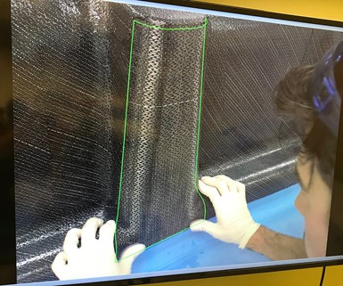
PlyMatch monitor accurately displays where to position the next ply to be laid up. Source | Systima Technologies
Taking the opposite tack, and falling somewhere within the spectrum of mixed reality applications, the Anaglyph Ltd. (London, UK) PlyMatch system projects 3D manufacturing space into the virtual realm. Specifically, PlyMatch provides a live feed of the work area, which is displayed on a monitor along with a super-imposed, computer-generated image of each ply to be laid up. The ply software image is generated from a CAD or design file and, because PlyMatch is self-calibrating, the images match up accurately, even when the camera or tool is moved. After an initial calibration, which takes only a few minutes, an optical sensor tracks the relative positions of the camera and tool, and the system’s controller updates the positional relationship in real time. The system is reportedly compatible with any CAD application that generates IGES or 3D DXF files. Alternatively, it can be used with Anaglyph’s proprietary composites design and analysis software, Laminate Tools, or with compatible layup data files produced by CATIA Composites Link (Dassault Systèmes, Vélizy-Villacoublay, France) or Fibersim (Siemens PLM Software, Plano, TX, US).
Applied Composite Engineering (ACE, Indianapolis, IN, US) has used PlyMatch to guide the company’s manufacture of a heated inlet for helicopter anti-icing system (see Learn More, p. 62). More recently, Systima Technologies (Kirkland, WA, US), a maker of energetic systems and components primarily for defense and space applications, put PlyMatch to work when the company brought composites manufacturing in-house in 2014. That’s when Eric Wightman came on board as director of structures and advanced materials, a department that has grown from a one-man operation to a staff of 12.
Having previously worked with PlyMatch when he was employed by ACE, Wightman recognized that the technology was a fit for the kind of work Systima would be doing. “We’re not a build-to-print shop; we’re a design firm,” he says, noting that, for a large majority of its projects, Systima builds only first articles. Many of these are long and narrow and feature complicated geometries. Wightman found that a laser projection system just wouldn’t work effectively or cost-efficiently with these geometries. “We would have needed three or four projectors, and calibration would have been much more involved,” he says. Such a system also would have had a six-figure price tag, where Systima’s PlyMatch implementation cost less than US$50,000.
Further, using PlyMatch, manufacturing such components has proven efficient and straightforward, Wightman asserts. Systima designs its products using CATIA, then exports an IGES file to the PlyMatch system. When the composites staff is ready to build a component, an operator performs PlyMatch’s initial calibration and is ready to begin layup in less than 5 minutes. Even positioning of plies while looking at the monitor is said to be straightforward— Wightman contends that an operator who already knows how to perform layup can be trained and proficient with PlyMatch in an afternoon.
Systima has built components using PlyMatch from the start, so Wightman does not have comparative data; but he estimates that layups could take at least twice as long as the current three weeks if it were performed using templates and ply books. He also emphasizes how important it is that the system has resulted in accurate, timely layup of flight-critical parts.
The PlyMatch system reportedly also can locate manufacturing or assembly-sequence features, such as inserts or bolt holes. Additionally, the complete build process can be digitally recorded to an .avi file, providing a record of each individual component, as built, and showing any deviations from nominal ply position or fiber orientation. For automated manufacturing, PlyMatch has the potential to be adapted to record machine movements and material placement relative to the nominal.
Anaglyph says it continues to upgrade PlyMatch, adapting new hardware technologies and software upgrades as they become available. Emmanuelle de Posson, marketing manager at Anaglyph, mentions camera and lens technologies, PC interfaces and PC peripherals as examples, and adds, “Currently we are working towards a totally wireless version, which is a challenge, given the requirements for long battery power and no loss of video picture quality.” Anaglyph also is working on methods to effectively accommodate larger tools and layups with sufficient accuracy and alignment. Additionally, a version of PlyMatch that uses an AR headset device is in development.
Virtually mapping rework and repair
Another major player in AR for composites applications is InFactory Solutions (Taufkirchen, Germany), an Airbus subsidiary created in 2016 to develop digital composites production solutions for Industry 4.0. In early 2017, Airbus qualified an InFactory sensor system for inline inspection on MTorres (Torres de Elorz, Navarra, Spain) automated fiber placement (AFP) equipment (see “InFactory Solutions qualifies AFP sensor on MTorres equipment with Airbus”). InFactory Solutions managing director Franz Engel indicated at the time that laser projection was being used to pinpoint the location of defects the sensors detected, but the company’s plan was to advance that application from laser projection to AR technology.
Heading up InFactory Solutions’ AR efforts, Dominik Karl, Technology and Project Leader Visualization-Augmented Reality, reports that many AFP systems currently have no visualization method, and workers must find defects with only their eyes. The company has now advanced its AR visualization technology to demonstrators in a laboratory environment (TRL 4), and they expect to test the tools in factory environments during the coming year. Additionally, in May 2018 the company commercially implemented a non-AR intermediate technology, a mobile display tablet, in an AFP production setting. The mobile display provides the operator with a visualization of the defect, along with information about the defect type, position and dimensions. “But it does not include visualization at the real part’s surface, and it offers limited support of localization and orientation,” Karl explains, distinguishing this technology from AR.

InFactory Solutions VisinPro application, under development, uses AR glasses to pinpoint a defect on the actual production surface, along with information that assists the technician in remediating the defect. Source | InFactory Solutions
InFactory Solutions is developing AR technology for two devices: an AR-capable version of a mobile display tablet, as well as AR glasses. As with laser projection and the non-AR tablet, the AR devices do not conduct inspections or perform data analytics. The company’s inline sensors still collect inspection data, which are analyzed via computer algorithms in the server. The server then feeds needed information to the AR device wirelessly.
The company houses its AR demonstration tools in its VisinBox AR laboratory and showroom. VisinBox technology currently focuses on two applications: VisinPro for manufacturing production, and VisinMaint for maintenance, repair and overhaul (MRO). “Future efforts will apply AR to assembly operations as well as training,” Karl adds.
The AR tablet builds on non-AR tablet technology. In addition to defect type, position and dimensions, the AR tablet is capable of guiding the operator to the defect position and then displaying production data and repair instructions on the real part surface at the defect position.
“Making virtual data available directly at the place of origin on the part surface” is the primary benefit of AR, says Karl. Compared to manual inspection and repair, inline inspection combined with AR-assisted rework and repair is expected to cut inspection time by 95%, rework time by 73% and total production time by 48%. Karl anticipates implementation of AR tablets in a production environment toward the end of this year.
The application of AR devices to manufacturing operations demands software development specific to the application.
Of course, the AR tablet is not a hands-free technology. This is where AR glasses come in. VisinBox AR glasses — currently, Microsoft HoloLens — display virtual data directly into an operator’s three-dimensional work space. (Karl mentions that the company regularly evaluates other AR glasses as it considers different customer needs.) Looking through the glasses in VisinPro, the worker sees the defect location, production data, such as the course and sequence of the defect, the nature of the defect (splice, twist, fuzzball, etc.), followed by repair instructions, repair status and the like. VisinMaint also displays vital information about structures and parts near the repair site. For example, an operator might be made visually aware of critical electronic components situated directly behind a delamination that is to be repaired.
One key technology aspect of AR applications is the correct overlay of virtual and production visual elements: The technology must be able to determine and track the position of the AR tablet or glasses relative to the part surface. To create and maintain this “common coordinate system,” the VisinBox tablet uses its onboard camera to detect an optical marker positioned on the part surface. A set of AR glasses uses infrared and camera sensors to determine its position within the work cell, and the server coordinates this information with the known positions of tooling, part surfaces and so on. “In the future,” Karl says, “the AR device’s position may be determined relative to a feature of the component.” This advancement would give the operator additional freedom of movement.
The application of AR devices to manufacturing operations demands software development specific to the application. Software development is required to track the device’s position, communicate manufacturing and inspection data to the device, enable the device to produce the visualization images, and enable the operator to interact with the visualized data (e.g., advance from one defect to the next). Furthermore, both hardware and software must be adapted to the particular production environment, compensating for surface reflection, lighting and other conditions. InFactory and others are hard at work on such programming, as are some AR device providers.
In the future, Karl envisions AR applications beyond part production to other aircraft manufacturing environments. For example, in aircraft painting, a physical stencil is typically used, and correctly positioning a stencil is a tedious and time-consuming operation. Karl believes that AR technology could easily assist stencil placement, and also assist quality workers in identifying targeted areas of the paintwork requiring touch-up.
Expediting assembly inspection
InFactory Solutions is not the only Airbus subsidiary involved in AR solutions for composites-related manufacturing. Testia (Toulousse, France), which specializes in inspection and quality-control solutions, is marketing Airbus’ Mixed Augmented Reality (MiRA) solution under the name Smart Augmented Reality Tool (SART). SART has been implemented at two Spirit AeroSystems (Wichita, KS, US) facilities where components for the Airbus A350 XWB commercial aircraft are produced.

Developmental AR tablet shows technician the actual repair site captured by the tablet’s camera, along with information about the nature of the damage as well as repair instructions. Source | InFactory Solutions
Airbus Group Innovation (Suresnes, France) developed MiRA technology to reduce the inspection time for tens of thousands of brackets that hold hydraulic pipes and wire bundles in place and attach them to the composite fuselage sections of the latest production aircraft. Using a tablet-based interface equipped with a camera for visual inspection, workers access the 3D model of the aircraft and compare the built and installed assemblies to their digital designs to inspect for missing, wrongly positioned or damaged brackets. At the end of the inspection, a report is automatically generated that includes details of any nonconforming parts that can be replaced or repaired quickly.
In the first internal deployment of MiRA, in 2011, the system reportedly dropped inspection time for the 60,000-80,000 brackets in an A380 fuselage from three weeks to three days. Now, under the SART moniker, Testia has deployed the system to composite bracket manufacturer Daher Socata (Tarbes, France) on all of its large fuselage element assembly lines for a major French manufacturer of business aircraft, and at the Spirit AeroSystems A350 fuselage manufacturing facility in Kinston, NC, US, and Saint-Nazaire, France.
Virtually ready
With the exception only of the Virtalis installation at Airbus’ Broughton facility, each VR and AR application covered here has followed successful implementation with rapid return on investment. These 3D visualization capabilities are providing composites engineers greater confidence that composites can be built and assembled as designed. This confidence is but one major benefit among many, not the least, the savings in time and material costs, the increase in part optimization, and other benefits already achieved by VR/AR technologies. Further, the data generated by VR/AR applications are expected to feed Deep Learning and other Smart Factory operations, taking the composites industry to even greater productivity and quality watersheds.


.jpg;maxWidth=300;quality=90;format=webp)


Related Content

Sustainability has come to composites and it's here to stay
It might be tempting to think of sustainability as a buzzword, but there are structural changes taking place in the composites industry that signal its permanence.
Read More
Materials & Processes: Fabrication methods
There are numerous methods for fabricating composite components. Selection of a method for a particular part, therefore, will depend on the materials, the part design and end-use or application. Here's a guide to selection.
Read More
Composites UK launches best practice guide for composites tooling
“Mould Tooling for Fibre-Reinforced Polymer Composites” is latest in Composites UK’s series of good practice guides, available online for free.
Read More
From sailplanes to composites repair: Growing composite training opportunities over the years
Mike Hoke discovered his interest in the composites industry at a young age. His journey eventually led him to Abaris Training Resources, which he owned and evolved for more than 30 years.
Read MoreRead Next

Composites end markets: Energy (2024)
Composites are used widely in oil/gas, wind and other renewable energy applications. Despite market challenges, growth potential and innovation for composites continue.
Read More
CW’s 2024 Top Shops survey offers new approach to benchmarking
Respondents that complete the survey by April 30, 2024, have the chance to be recognized as an honoree.
Read More
From the CW Archives: The tale of the thermoplastic cryotank
In 2006, guest columnist Bob Hartunian related the story of his efforts two decades prior, while at McDonnell Douglas, to develop a thermoplastic composite crytank for hydrogen storage. He learned a lot of lessons.
Read More