
3D printing CFRP molds for RTM flaperon, exoskeletons and more
The Chair of Carbon Composites at TU Munich is advancing composite additive manufacturing via large-scale extrusion, continuous fiber printing, integrating heating into tools and more.


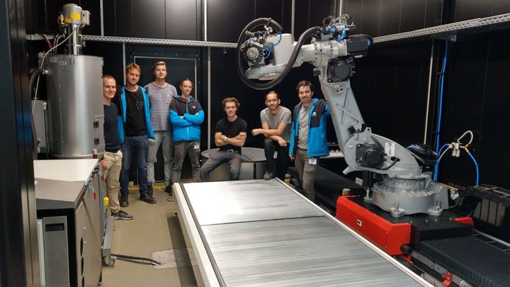
The Chair of Carbon Composites (Lehrstuhl für Carbon Composites or LCC) was established in 2009 in the department of Mechanical Engineering at the Technical University of Munich (TUM, Munich, Germany) with funding from SGL Carbon (Wiesbaden, Germany). Its mission is to perform R&D in carbon fiber-reinforced polymer (CFRP) materials, processes and applications, including projects in simulation and testing. A “chair” in the German university system is the smallest unit comprising a professor and his team. The LCC team is led by Prof. Dr. -Ing. Klaus Drechsler and currently employs 30 full-time researchers. Though SGL funding came to an end in 2016, the LCC has continued its leadership in composites R&D, which includes building the mold for the lower half of the Multifunctional Fuselage Demonstrator (MFFD), see sidebar below, and now also includes 3D printing/additive manufacturing.
This blog began when CEAD (Delft, Netherlands) informed me that LCC had bought one of its extruder-based AM flexbot systems for 3D printing using a robot arm. My subsequent interview with LCC researcher Patrick Consul, however, revealed a treasure trove of projects, including COMBO3D, within Clean Sky 2, to 3D print a thermoplastic composite RTM mold for the production of a thermoset composite aircraft flaperon, and EMOTION to produce the tool for molding the lower half of Clean Sky 2’s thermoplastic composite Multifunctional Fuselage Demonstrator (MFFD) as well as a secondary partial tool to demonstrate how the same fuselage might be produced via direct in-situ consolidation (out of autoclave). I found the whole discussion of how TUM has reached this point and where it is headed to be interesting.


MMFD lower half mold
See my Feb 2020 blog: “Proving out LM PAEK welding for Multifunctional Fuselage Demonstrator”. This sidebar is taken from the Feb 2020 paper, “Development of a Multifunctional Fuselage Demonstrator” by Bas Veldman, program manager for the MFFD at GKN Fokker (Hoogeveen, Netherlands).
The shell of the lower half of the MFFD consists of a thermoplastic skin, stiffened with welded stringers, clips and frames. The manufacturing process to be demonstrated comprises three key steps:
- Prepreg tape for the demonstrator’s large skin is laid up on a flat, tilted table by NLR’s existing laser AFP machine.
- Layups are transported robotically with suction cups to a female consolidation mold and draped into it without heating.
- After vacuum bagging, the skin is consolidated in an autoclave.
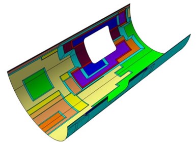
Thickness variations in the 8-meter-long and 4-meter-wide lower fuselage section of the Clean Sky 2 Multifunctional Fuselage Demonstrator.Photo Credit: Fig. 4, “Development of a Multifunctional Fuselage Demonstrator” by Bas Veldman.
Using a female consolidation mold offers a much simpler (flat) surface than for a male tool while directly controlling aerodynamic constraints on the skin’s outer surface quality.
The MFFD project also calls for out-of-autoclave processes to be investigated — starting in parallel to the large multifunctional fuselage demonstrator — in a subsequent smaller size demonstrator. In particular, in-situ thermoplastic composite manufacturing in which consolidation is achieved during the lay-up, will be considered, since it may completely eliminate the autoclave step, and hence reduce the manufacturing to a single-step procedure.
Enhanced Mould for Thermoplastic Fuselage in and out of Autoclave Consolidation, or EMOTION (https://cordis.europa.eu/project/id/864474), is the Clean Sky 2 project for producing the MFFD lower shell tooling. “It sounds simple,” says Patrick Consul from the project’s coordinator, TU Munich, “but it is actually quite challenging as it needs to be heated to 400°C. This is well above the temperature range in which Invar36 doesn’t have a significant CTE [coefficient of thermal expansion].” Invar is commonly used for composite molding tools because of its low expansion during high-temperature cure cycles. However, Invar’s CTE does increase with temperature. “The challenge,” notes Consul, “will be to control the thermal expansion during heat-up and cool-down for the 8-meter by 4-meter mold and fuselage skin during cure.”
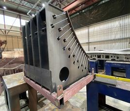
This small-scale (1-meter by 1-meter base area) trial tool for the EMOTION project uses different materials for shell and backing structure to be used at 400°C. The shell is held in place by fasteners acting as tension springs so the backing structure can move to minimize distortion due to CTE difference between it and the shell. This floating shell allows the use of regular steel in the backing structure vs. more costly alloys and is based on a concept from partner Ostseestaal.
Progression in additive manufacturing
“We are 8-9 people working on additive manufacturing within the LCC,” says Consul. He begins the history of this work with the LCC’s purchase of a laser-assisted thermoplastic composite tape placement machine from AFPT (Dörth, Germany) in 2012. It later added a Coriolis Composites (Quéven, France) machine to enable automated fiber placement (AFP) of thermoset prepregs. The first filament-based desktop printers were purchased in 2017. “I also joined in 2017 to assist with developing new applications and research projects, including proposal writing, for example, to Clean Sky 2.” He explains that Clean Sky 2 projects are awarded based on proposals submitted to topic managers in response to publicly released Calls for Proposals (CFP). LCC succeeded in its proposals for the CFP08 COMBO3D project and the CFP09 EMOTION project. Both are discussed below.
“We have a few other projects, some looking at 3D printing with continuous fiber reinforcements,” says Consul. “Others use a laser-integrated print head to preheat the composite substrate to print on already-consolidated CFRP parts or to increase interlaminar shear strength (ILSS) between printed layers. Another project explores tooling applications, for example, where you have a low number of specialized composite parts.”
“These projects are continuously supported by numerical simulations in order to predict the behavior of the additive manufactured parts during and after the printing process,” he continues. “The LCC is also involved in a project with the Imperial College of London which aims to manufacture exoskeletons using 3D printed CFRP. Another project researches lattice structures in order to optimize the properties of 3D printed parts with respect to stiffness, strength or energy absorption.”
Progression in printers

The Apium P220 printer uses a heated plate around the print head to maintain the high temperature required to ensure sufficient crystallization for the semi-crystalline PEEK and PEKK thermoplastic polymers, ensuring good mechanical properties. This benefit is furthered by minimizing temperature gradients and thermal stress within the print.Photo Credit: Apium
”We started by using a simple 3D printer based on FDM (fused depositionmodeling) from Apium (Karlsruhe, Germany) to print specialized test fixtures that need high stiffness,” Consul explains. “The printer was 3-meters-long by 1-meter-wide with a high material output to reduce print time. Although it could not use continuous fiber, it was well-designed for printing with PEEK, PEKK and chopped carbon fiber-reinforced PEEK. It not only used a heated bed but also a heated plate around the printhead which helped to produce homogeneous temperature distribution in the prints, reducing thermal stress and ensuring crystallization.”
“We also had a Markforged (Cambridge, Mass., U.S.) printer for a while and then got an Anisoprint [Esch-sur-Alzette, Luxembourg],” says Consul. Although the Markforged printer did enable FDM with continuous fiber, the LCC team chose not to keep it. “The problem we had was that the system was very closed,” explains Consul. “The slicer software from Markforged was too difficult to use for research because it severely limited what we could do. We could only print a layer of continuous fiber material and then a layer of short fiber-reinforced thermoplastic filament on top. The slicer that generates the code wouldn’t accept G-code from us. So, there was no way to tell the machine to print it the way we wanted with continuous fiber in each layer, etc.”
When asked about this, Markforged explains that its systems were never intended to be used for research, but instead designed to be simple and robust for widespread use in making parts, utilizing rule-based fiber pathing and requiring low effort and time to configure the slicer. Its Eiger software does allow users to configure layers individually, and Markforged welcomes feedback and prioritizes improving the user experience for its customers.
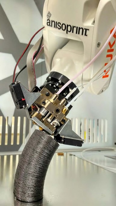
“Anisoprint, which uses a completely open G-code slicer, gave us more accessto the process,” says Consul. “It’s also capable of printing continuous carbon fiber and not just in 2D layers, but also out of plane, in 3D curves. We have an Anisoprint print head for a small Kuka robot, capable of producing 1 meter by 1 meter parts, which is larger than most desktops, but small for a robot system."
But what about Anisoprint’s dual-matrix thermoset-thermoplastic (TS-TP) materials? As explained in my 2019 blog on Anisoprint “… it first impregnates continuous fiber reinforcement with a thermoset polymer and then extrudes this into the melted thermoplastic filament during printing.” Consul replies that the adhesion between the TS filament and the TP is pretty good. “On our first trials, we could get higher fiber volume content compared to the Markforged printer, but this was because we could modify the G-code. The Anisoprint print head pushes the TS filament into the TP and then lays that. We’re planning to use that printer for exoskeleton parts. It’s an easy way to get higher-strength fibers integrated."
Extruded pellet printers
The next progression was to a large-scale printer, first with short fiber-reinforced TP and then continuous fiber TP. “We first developed an extruder mounted on a robot, and then our interest in the CEAD machine followed quickly. We are hoping to get continuous fiber integrated into both of these systems next year.”
But why did you need the CEAD machine if you already had an extruder on a robot arm? “The initial extruder was the beta version of a Dyze Pulsar pellet extruder, which outputs a maximum of about 2kg/hr and roughly 1kg/hr with PAEKs, but it struggles with more than 20% carbon fiber loading,” says Consul. “However, the average output is lower because the robot accelerates and decelerates often during printing. For COMBO3D, the initial small-scale mold halves were already requiring at least 36 kilograms, so we needed around 48 hours to print a single half. We also had to have someone always with it because errors, like a blocked material feed line or part warping, could happen at any time.”
Because the COMBO3D final demonstrator is about 10 times larger than the initial small-scale parts, printing it using this first extruder system wasn’t feasible, says Consul. “Also, some of the materials Victrex supplied us with had a higher viscosity and this first extruder could not provide enough torque to extrude those polymers. With the CEAD printer, we have a maximum output of around 12.5 kg/hr, and after a few hours of trials, we had a stable average output of around 5-6 kg/hr. This enabled us to print the small-scale mold half in under 8 hours and lets us use higher fiber contents to reduce the warping, making the process overall easier to control.”
“So while the Pulsar already allowed us to use pellets, achieve high material output and take advantage of a robot’s degrees of freedom,” he continues, “the CEAD printer extends our capabilities towards larger parts, higher fiber contents and a wider range of polymers. The Pulsar bridges the gap between our filament based printers and the CEAD, not just in output but also in nozzle size and resulting detail of the prints.”
CEAD AM Flexbot technical data:
- AM Flexbot technical data:
- Pellet based extrusion prints up to 12.5 kg/hr (unreinforced and short fiber-reinforced)
- Processing of materials up to 450°C
- Build volume 3000 x 1200 x 1700 millimeters
- Build plate on a rotary table or flat table (heatable)
- Reworking by means of a milling head.
COMBO3D
The objective of this Clean Sky 2 project is to 3D print a mold to produce a demonstrator composite flaperon (1.5 by 3 meters) for a large passenger aircraft, part of Work Package A-3.1: Multidisciplinary wing for high and low speed. The goal for using additive manufacturing is to shorten the lead-time for tool production. The project started in January 2019 and will end March 2021. Partners include Alpex Technologies (Mils bei Hall, Austria), lightweight metals specialist Leichtmetallkompetenzzentrum Ranshofen (Ranshofen, Austria) and Victrex (Thornton Cleveleys, U.K.), supplier of the high-performance thermoplastic polyaryletherketone (PAEK).
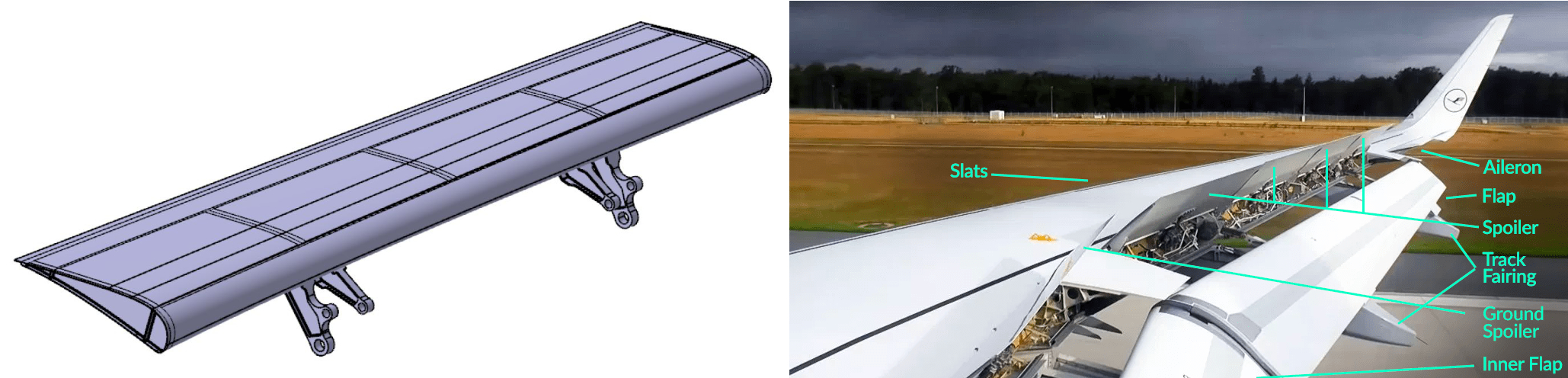
The flaperon demonstrator in COMBO3D is shown at left in Fig. 9 from the 8th Call for Proposals document issued by Clean Sky 2. However, it appears to more accurately match the size and geometry of the flap for an A320 wing in the image at right.Photo Credit: Clean Sky 2 CFP 08, p. 195 and “How Airplane Wings Work” by Mike Arnot, 2019.
Another key part of the project is to demonstrate that this carbon fiber/epoxy flaperon can be made with resin transfer molding (RTM) instead of autoclave-cured prepreg. The RTM part will cure at the same 180°C as the autoclave parts. To ensure thermal stability, the tool will be printed with short carbon fiber-reinforced PAEK, which has a melt temperature of 305°C.
In order to shorten the cure cycle, the 3D printed mold will integrate active temperature control. “We must be able to heat up and cool down the mold faster compared to the autoclave,” Consul notes. “We will use a mesh of electrical heating elements 3 millimeters below the mold surface and also integrate printed channels for heated oil or air at 6 millimeters below the mold surface. In this way, we can heat the mold surface very quickly but also use the channels to heat throughout the tool volume. We are aiming for a heating and cooling rate 50% faster than the autoclave and feel confident we can achieve at least a 30% faster rate.”
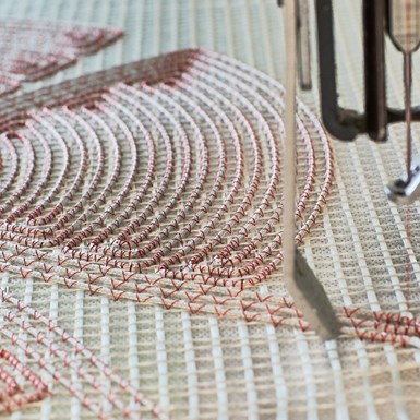
In tailored fiber placement (TFP), wires or other heatable filaments can be stitched onto a wide variety of substrates.Photo Credit: Qpoint Composite
What are the heating elements to be integrated into the 3D print? “We have used tailored fiber placement (TFP) of carbon rovings on a glass fiber textile as heater elements to realize different heater zones in a CFRP mold for a helicopter rotor blade,” Consul explains. “This was for a Clean Sky 1 project that we completed working with QPoint Composite (Dresden, Germany). We will work with a similar concept on the COMBO3D mold.”
The whole development of the printed tool is supported by simulation. The tool design will be optimized by implementing the heating and cooling system in a thermal simulation. The manufacturing process will also be simulated, supporting the printing process by generating knowledge about the temperature distribution during printing and correlating it with path planning.
CEAD machine installation and project progress
“The CEAD system was delivered very quickly — from order to installation was only 6 months,” says Consul. “By this time, we had completed materials testing, designed the plate tooling and had started printing small parts. We were worried that it would take a long time to get the process running well with the CEAD AM Flexbot, but it worked well with the first trials.”
Plate tooling? “It’s a small mold, already integrating cooling channels and heater elements to produce CFRP plates for coupon testing,” he explains. “This testing was to ensure that the quality of our 3D printed CFRP RTM mold will be comparable to the current CFRP that Saab produces with their autoclave process.”
Unfortunately, the project was interrupted by COVID-19, “but now all is going well and we’re catching up,” says Consul. And what about using PAEK for the 3D printed mold? “The only issue currently is that the Tg [glass transition temperature] for PAEK is 130-140°C, which is lower than the 180°C cure for the demonstration part,” notes Consul. “So, we still have to see how many cycles we can complete at the cure temperature before creep happens or the surface is damaged.”
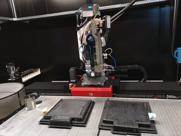
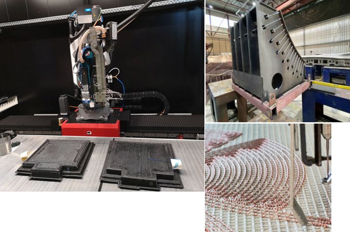
The two printed “blanks” for the COMBO3D project’s RTM mold halves before machining the channels inside. The white cup on the side of each blank covers wires for the internal heating that project out enabling connection to an electrical power source. Each part weighs about 35-40 kg, making them some of the heavier PAEK parts 3D printed to date.
Photo Credit: Chair of Carbon CompositesCEAD machine in other projects?
“We’re applying for a project in aerospace tooling that starts next year with GKN Aerospace Deutschland (Munich) using the CEAD machine and polyethersulfone (PESU),” says Consul. [Note: GKN in Germany makes composite wing flaps for the A330 and A350 as well as ailerons for the Bombardier Global family of business jets.] “CEAD will be part of this responsible for machine development for continuous carbon fibers. We’re also planning to use the CEAD machine internally to make prototype molds for RTM which otherwise would have been subcontracted out. It gives us a benefit in accelerating the work.”
Consul notes that PESU has a higher Tg than PAEK. “It is also amorphous, not semi-crystalline, so it should be easier to print, although creep resistance might be an issue. What we’re trying to do is avoid PEI (polyetherimide). In the past, we looked at the issue of PEI bonding to epoxy resin. RTM6 [epoxy for RTM] dissolves PEI which drives good adhesion between the two. This is exactly what you don’t want in 3D printed molds that need to release the parts, not stick to them.”
Future industrial (and flying) 3D printed composites
In discussing some of the other projects that LCC is pursuing in additive manufacturing, I ask Consul what has held CFRP back in exoskeletons? “Because exoskeletons need to be adapted to each wearer, the parts are specialized so the volume is not large,” he replies. “Our project aims to enable the production of patient-specific lower limb exoskeleton components to enable the production of a patient-specific exoskeleton in less than 24 hours. These exoskeletons will support the rehabilitation of stroke patients based on their biophysical profiles and unique medical rehabilitation needs.” (See the CW article, “C-FREX exoskeleton depends on CFRP …”)
“People have the concept that 3D printing can print any part, but you first have to have experience with 3D printing and with composites. For example, there are often issues with layer to layer adhesion and anisotropy that must be understood. 3D printed composite parts won’t be the same design as those currently made out of plastic and metal.”
He notes there are still issues to overcome for using 3D printed composites for production of high-performance aircraft parts, for example: How do you design these parts for additive manufacturing? How do you identify parts where additive manufacturing adds value? “Aerospace tooling is the main field of applications that our team is looking at right now,” says Consul. “3D printing the mold fits well. These molds must withstand all of the same curing conditions as the parts but there is less risk associated with molds vs. flying parts. A good example is rib stiffeners for wings, where there is a high number of different parts but not many cycles per part. So, this is a good way to generate experience with the technology. It is too early to try for structural parts that will fly. We will aim for this long-term, but printing tools will allow us to get the 3D printing process stable enough with high-performance properties and also develop the ability to accurately predict these parts and processes in simulation.”


.jpg;maxWidth=300;quality=90;format=webp)


Related Content

Digitizing tools for composites production
Alpex Technologies focuses on industrialization, process and part intelligence and biocomposites in its next generation of tooling systems.
Read More
Plant tour: Airtech International, Springfield, Tenn., U.S.
Fifty years of supplying materials for composites manufacturing includes custom fabrication and now aims to advance 3D-printed tooling, parts and new resins.
Read More
Materials & Processes: Tooling for composites
Composite parts are formed in molds, also known as tools. Tools can be made from virtually any material. The material type, shape and complexity depend upon the part and length of production run. Here's a short summary of the issues involved in electing and making tools.
Read More
ATLAM combines composite tape laying, large-scale thermoplastic 3D printing in one printhead
CEAD, GKN Aerospace Deutschland and TU Munich enable additive manufacturing of large composite tools and parts with low CTE and high mechanical properties.
Read MoreRead Next

From the CW Archives: The tale of the thermoplastic cryotank
In 2006, guest columnist Bob Hartunian related the story of his efforts two decades prior, while at McDonnell Douglas, to develop a thermoplastic composite crytank for hydrogen storage. He learned a lot of lessons.
Read More
CW’s 2024 Top Shops survey offers new approach to benchmarking
Respondents that complete the survey by April 30, 2024, have the chance to be recognized as an honoree.
Read More
Composites end markets: Energy (2024)
Composites are used widely in oil/gas, wind and other renewable energy applications. Despite market challenges, growth potential and innovation for composites continue.
Read More