
RTM-based redesign advances safety for one-of-a-kind wind tunnel
Glass fiber and honeycomb spacers between compressor blades get upgraded to a higher factor of safety with less weight using solid carbon fiber and RTM.

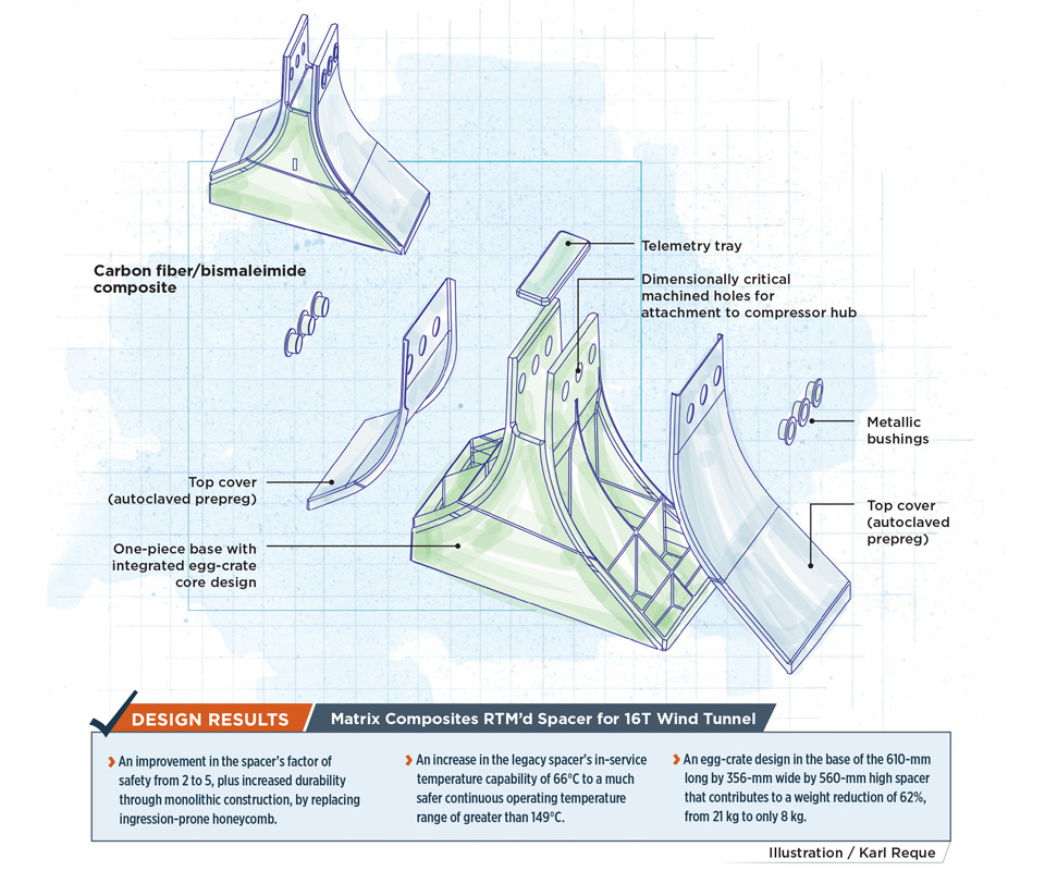
Design results: Matrix Composites RTM’d Spacer for 16T Wind Tunnel
An improvement in the spacer’s factor of safety from 2 to 5, plus increased durability through monolithic construction, by replacing ingression-prone honeycomb.
An increase in the legacy spacer’s in-service temperature capability of 66°C to a much safer continuous operating temperature range of greater than 149°C.
An egg-crate design in the base of the 610-mm long by 356-mm wide by 560-mm high spacer that contributes to a weight reduction of 62%, from 21 kg to only 8 kg.
Illustration: Karl Reque
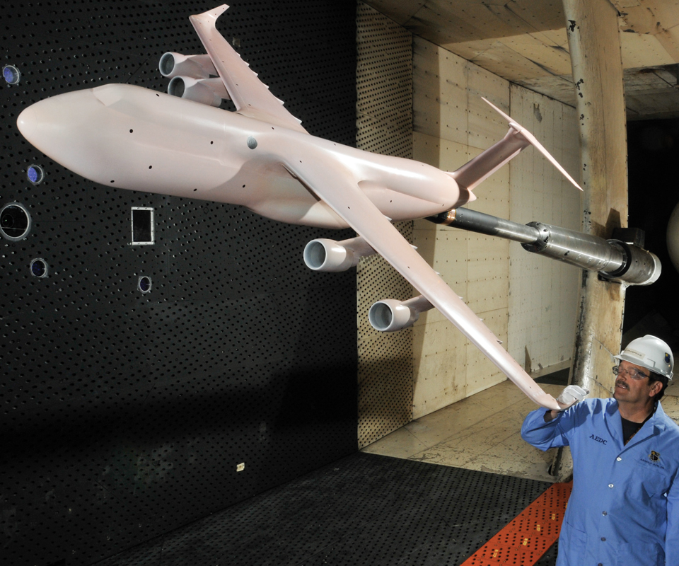
Fig. 1: A top wind tunnel for a half-century
The 16T wind tunnel, used in almost every major DoD and US space flight vehicle program for 55 years, was fitted with the new spacers, which are bolted onto the hub of its compressor. The compressor’s nosecone nacelle can be seen at far right above the technician. Source: AEDC
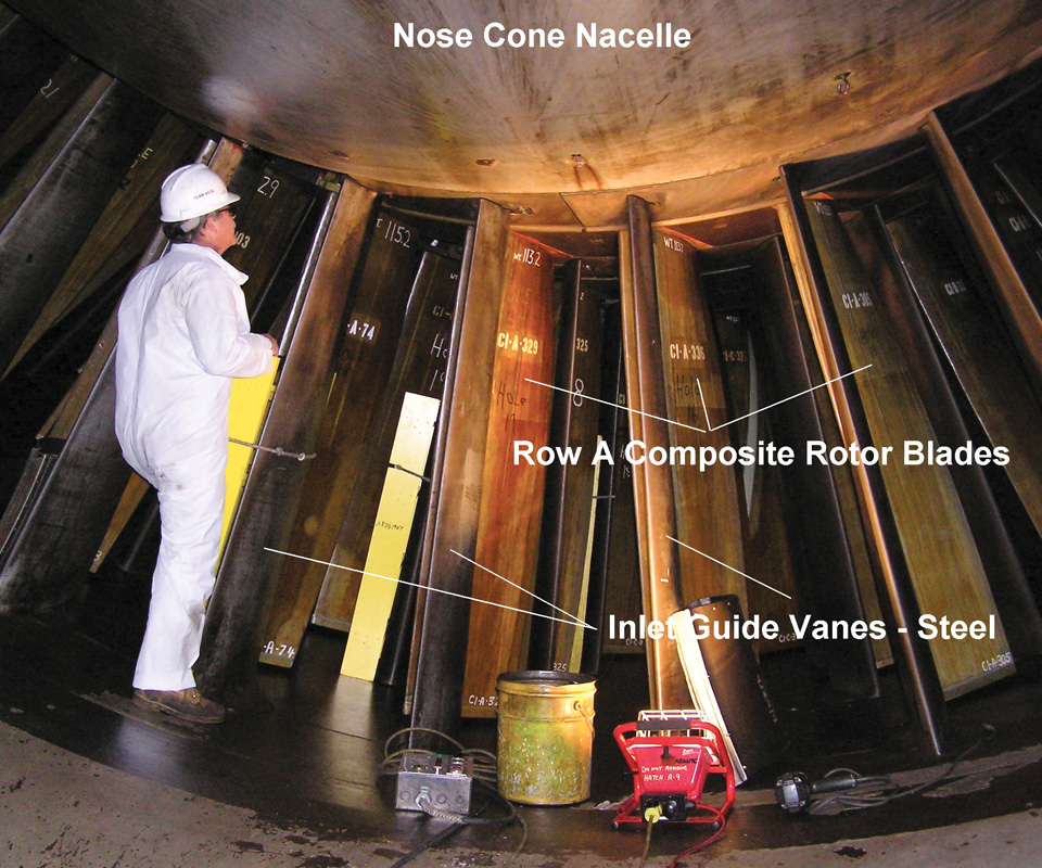
Fig. 2: Avoiding potential compressor failure
Spacers prevent the wind tunnel compressor’s rotor blades from impacting the adjacent stator blades (the first row of stator blades are labeled here as inlet guide vanes), which would cause disastrous failure.
The spacers are bolted onto the compressor hub, positioned in between the rotor blades. Source: AEDC
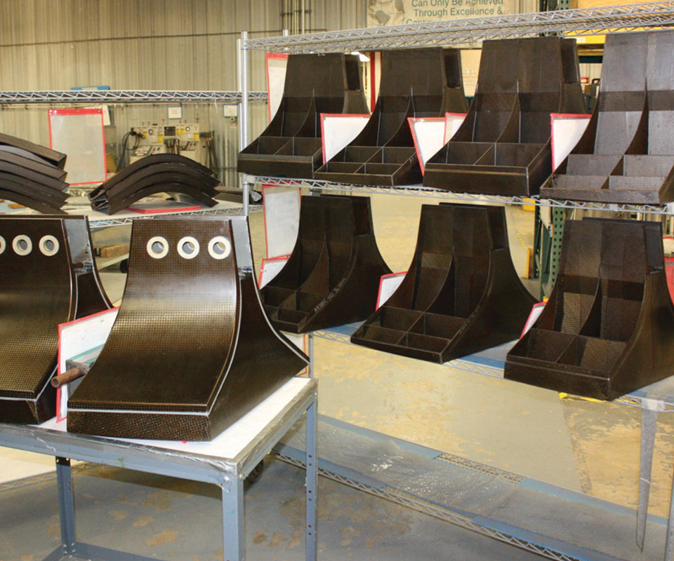
Fig. 3: Spacers with a superior safety factor
The redesigned composite spacers (front, left) for the 16T wind tunnel feature monolithic laminates, both in the single-piece RTM base with its integrated egg-crate reinforcement grid (visible in the shelves at right and illustrated) and in the autoclave-cured prepreg top covers (shelved at top left). Holes are machined at the top for bolting spacers to the 16T compressor hub. Source: Matrix Composites
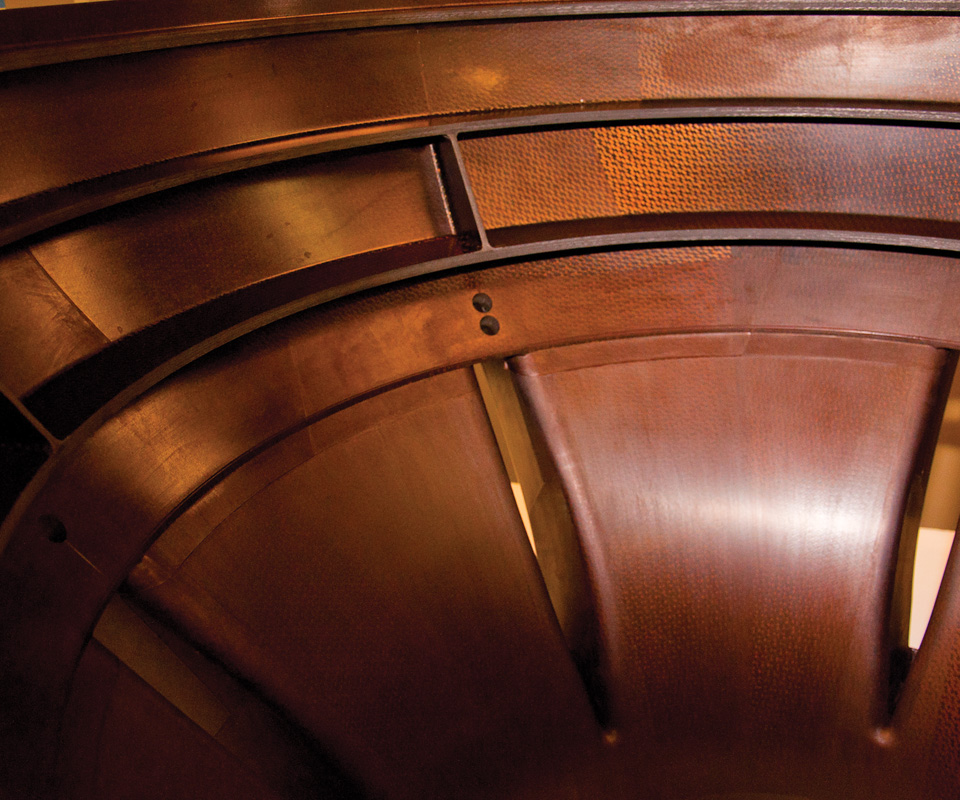
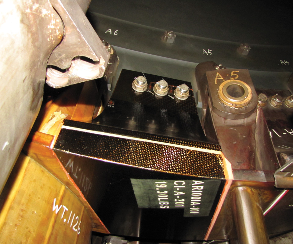
Fig. 4: Part complexity with cycling simplicity
This view of a high-temperature composite structure produced by Matrix Composites for another project (an aircraft engine) shows the complexity and flawless surfaces possible in the single-piece moldings produced via Matrix Composites’ RTM process. Source: Matrix Composites.
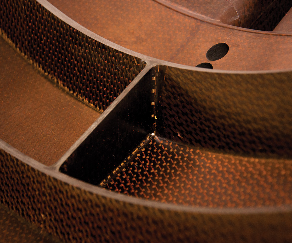
Another view of the high-temperature composite structure produced by Matrix Composites.


The Arnold Engineering Development Complex (AEDC, Arnold Air Force Base, TN, US) is the world’s largest, most advanced collection of flight simulation test facilities. Many of its 55 wind tunnels have capabilities unmatched elsewhere. The “transonic” 5m by 12m long test section for tunnel 16T, one of three tunnels in the AEDC’s Propulsion Wind Tunnel Facility, is one of these exceptional assets — a workhorse that can test models at air speeds from Mach 0.05 to 1.60, while simulating unit Reynolds numbers from 0.03 to 7.3 million/ft and replicating altitude conditions from sea level to 23 km (Fig. 1).
Chris Gernaat, structural analysis engineer for 16T, says it has supported almost every major US Department of Defense (DoD) and space flight vehicle program in the past 55 years. “We’re currently doing work for the US Air Force, NASA and commercial space companies, among others.”


Gernaat was a technical team member on the project to replace the tunnel’s previous glass fiber/epoxy and Nomex honeycomb-cored spacers with a new generation of composite structures. Positioned between the blades of 16T’s 600-rpm, 9.1m-diameter, three-stage compressor, the spacers hold the blades in place in the absence of centrifugal force while at rest and during compressor ramp up and ramp down. They prevent rotor blades from impacting adjacent stator blades, which could cause disastrous failure (Fig. 2, p. 70). Despite the previous spacers’ 35 years of service, their safety factor of 2 (load carrying capacity of two times the ultimate in-service load) left much to be desired in terms of risk mitigation. “Our main goal was to increase the factor of safety,” he says.
Developing a bid-winning design
When the project was offered worldwide, Matrix Composites Inc. (Rockledge, FL, US) turned in the winning bid. “I can’t say it was any one thing that won the contract for us, beyond meeting the technical objectives at an attractive cost,” says Matrix president Dave Nesbitt, whose background includes parts production for NASA’s Space Shuttle and US military and commercial aerospace companies. “But a lot of it had to do with our RTM experience.” He notes the company uses a range of processes, “but our closed molding capability is what sets us apart.”
Notably, the bid solicitation didn’t specify a manufacturing process. “We were given the design envelope and critical attachment points as well as operating requirements,” Nesbitt recalls. The spacers feature a complex shape and would be subject to high loads in a high-temperature environment, thanks to the friction of compressed air and the compressor’s rotational speed. “The spinning parts are rotating with a 1,000G load, so balance in the compressor is crucial,” he points out, “which translates into a need for exceptional part-to-part repeatability.” Although this is where RTM excels, its selection wasn’t a given, but became clear only after the structural design was explored.
Nesbitt says the shape’s complexity was the big challenge initially. “Our technical team brainstormed half a dozen conceptual designs, staying open to process, geometry and assembly options,” he explains. “We then did a trade evaluation, rating the designs on weight reduction, tooling cost, producibility, production cost, etc., and finally selected the best-rated option.”
Using Dassault Systèmes (Waltham, MA, US) CATIA software for solid modeling and NEi Nastran (AutoDesk, San Rafael, CA, US) for structural analysis, the team determined that monolithic composite laminates with an egg-crate reinforcement grid in
the base would achieve a safety factor of 5. The laminate transitions from 2.5 mm thick at the egg-crate partitions up to 16.3 mm in the plate where holes were machined for attachment to the compressor hub (Fig. 3, p. 70). Each 610-mm-long by 356-mm- wide by 560-mm-high spacer body would be produced as an integrated, single-piece unit, using RTM.
Materials selection
The trade study led to 5250-4 bismaleimide (BMI) resin from Solvay Composite Materials (Tempe, AZ, US) and IM7 carbon fiber from Hexcel (Stamford, CT, US). “This is the same material system qualified on multiple fighter jet programs supported by Matrix,” Nesbitt points out, “so it had a significant database, which was very important.”
“We did have to do some supplementary allowables testing at elevated temperature,” Nesbitt acknowledges. “The established database had ambient temperature, CTD [cold temperature dry] and ETW [elevated temperature wet] data, but that temperature wasn’t representative of the actual operating environment, so we performed additional testing.”
For the fabric, Matrix selected a 4-harness satin, woven by BGF Industries Inc. (Greensboro, NC, US) and tackified by Solvay. It provides 0° and 90° ber orientations but is more pliable than plain or twill weaves and more easily conforms to complex shapes.
Topsides, tooling and tolerances
To enhance durability, the initially open spacer body design was fully enclosed. Matrix designed the curved right and left covers that form each spacer’s “top” surfaces as well as the central telemetry tray (see drawing). These would be fabricated using the same fiber and resin as the RTM’d base, but in prepreg format with 40% resin content. After hand layup and autoclave cure, the covers and tray would be bonded to the base structure.
Tools and fixtures — made mostly from steel and hard-coat aluminum — were designed in-house but manufactured by subcontractors. “In order to keep the cantilevered blades from hitting the spacers and each other, we had to calculate the tolerance on the suction side of the blade vs. the pressure side — these tolerances were different due to the different loads,” observes Matrix engineering manager Ryan Wood. He explains that each spacer is bolted to the compressor hub and each sits between individual 52-kg blades. “There is a 5,000-lb [2,268-kg] side load on the spacer from the abutting blade. We had to model the spacer structure with this side load in order to predict the torsional deflection and make sure we maintained both blade suction and pressure side tolerances.” Analyzing loads in this complex dynamic environment required a time-consuming effort.
A three-stage compressor, finally, has three rows of blades and spacers in graduated sizes. Therefore, the spacers required three unique sets of multi-piece molds. To reproduce the egg-crate structure and overall geometry and meet the tolerance requirements for each row, without bridging in the corners, each set required as many as 70 pieces of tooling. Further, a separate tool set was required for the covers.
Molding, bonding and machining
When tooling was complete, production commenced. “The spacer body was made using our standard, high-pressure RTM process,” says Nesbitt. “Standard” in this case is RTM equipment that Matrix Composites designed and produced in house, which achieves >300 psi in the mold and was used to manufacture more than 6,000 fracture-durable components for the F-22 Raptor aircraft program. RTM cycle time for the bases and autoclave cure for the covers was roughly nine hours, including ramp-up and cool-down. A postcure for all parts, to enable the spacers to operate at temperatures greater than 149°C on a continual basis, was of similar duration.
Each postcured piece was inspected. “This is pretty standard in the aerospace industry,” says Wood. Matrix subcontracted nondestructive ultrasonic A-scan inspection to Arcadia Aerospace Industries (Punta Gorda, FL, US), now part of Applus+ Laboratories (Barcelona, Spain).
After inspection, covers and telemetry trays were bonded to the spacer bases with Henkel’s (Rocky Hill, CT, US) Hysol EA 9394 epoxy structural adhesive. “Of course, we first did a dry-fit inspection,” says Wood. A FARO Arm (Faro Technologies, Lake Mary, FL, US) coordinate measuring machine was employed to ensure piece dimensions were exact prior to bonding. “We used a purpose-built bond fixture to apply pressure to the bondlines,” he adds. The adhesive cured at room temperature overnight, after which the part was removed from the fixture and postcured at 66°C.
After bonding came machining. “There are six holes that allow attachment to the compressor hub,” says Nesbitt. “This is the most dimensionally critical area of the assembly,” he adds, explaining that during installation, there must be a slip-fit of the bolts through these machined holes. Machining was designed to account not just for the metallic bushings but also for the adhesive bondline thickness used to bond them in, while the bond fixture Matrix designed maintained axial alignment of the bushings within the holes.
RTM as an enabler
In all, Matrix Composites delivered more than 200 spacers, with the safety factor of 5 and a 62% weight savings. “Even though we didn’t specify it, that decrease in weight has been a good benefit for us,” says Gernaat. “The technicians have to pick the spacers up over their heads to install them, so an 18-lb [8-kg] spacer vs. the previous 47-lb [21-kg] version has been much easier to handle.”
Although the legacy and updated designs were both bonded assemblies, the lack of core material in the RTM’d spacer also is an improvement. “The honeycomb core tended to soak up oil,” he says, which deteriorated the parts and increased their weight, causing balance issues. “We’ve been running these spacers for more than 18 months, and the composite spacer structure has performed well.”
“I don’t think it would have been possible to create the egg-crate structure without RTM,” Nesbitt contends. He asserts that with other composite processes,the necessary part-to-part repeatability and laminate quality would have been a challenge (Fig. 4). “We have often found RTM to be an enabling technology,” he sums up, “and the 16T Tunnel spacer program is just one example.


.jpg;maxWidth=300;quality=90;format=webp)


Related Content

TU Munich develops cuboidal conformable tanks using carbon fiber composites for increased hydrogen storage
Flat tank enabling standard platform for BEV and FCEV uses thermoplastic and thermoset composites, overwrapped skeleton design in pursuit of 25% more H2 storage.
Read More
Carbon fiber in pressure vessels for hydrogen
The emerging H2 economy drives tank development for aircraft, ships and gas transport.
Read More
One-piece, one-shot, 17-meter wing spar for high-rate aircraft manufacture
GKN Aerospace has spent the last five years developing materials strategies and resin transfer molding (RTM) for an aircraft trailing edge wing spar for the Airbus Wing of Tomorrow program.
Read More
Materials & Processes: Composites fibers and resins
Compared to legacy materials like steel, aluminum, iron and titanium, composites are still coming of age, and only just now are being better understood by design and manufacturing engineers. However, composites’ physical properties — combined with unbeatable light weight — make them undeniably attractive.
Read MoreRead Next

CW’s 2024 Top Shops survey offers new approach to benchmarking
Respondents that complete the survey by April 30, 2024, have the chance to be recognized as an honoree.
Read More
Composites end markets: Energy (2024)
Composites are used widely in oil/gas, wind and other renewable energy applications. Despite market challenges, growth potential and innovation for composites continue.
Read More
From the CW Archives: The tale of the thermoplastic cryotank
In 2006, guest columnist Bob Hartunian related the story of his efforts two decades prior, while at McDonnell Douglas, to develop a thermoplastic composite crytank for hydrogen storage. He learned a lot of lessons.
Read More