
Wind blades: Pi preforms increase shear web failure load
Easily coinfused structural joint increases ultimate strength and fatigue life, offering solutions for designers as blades get longer and move offshore.

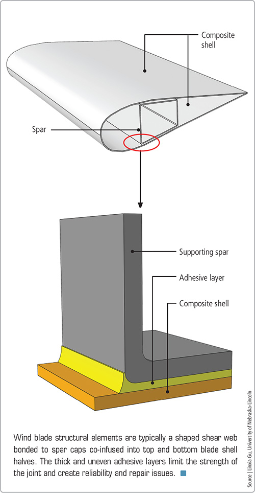
Wind blade structural elements are typically a shaped shear web bonded to spar caps co-infused into top and bottom blade shell halves. The thick and uneven adhesive layers limit the strength of the joint and create reliability and repair issues. Source: Linxia Gu, University of Nebraska-Lincoln
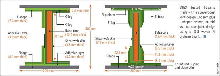
3TEX tested I-beams made with a conventional joint design (C-beam plus L-shaped braces, at left) vs. its new joint design using a 3-D woven Pi preform (right). Source: 3TEX
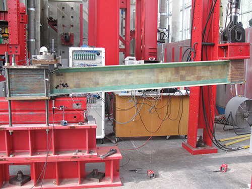
Both types of 2.7m/8.9-ft beams were clamped and cantilever-loaded to simulate wind blade service, during tests conducted at the Constructed Facilities Laboratory at North Carolina State University. Source: 3TEX
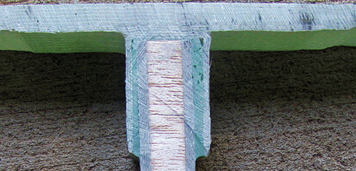
3-D woven textiles are stitched through the entire thickness in the center, but only partially through at the outer edges. This allows portions of the reinforcement stack to fold at right angles to form the Pi “legs.” The legs form a slot that receives the shear web, with enough additional space to allow for adhesive (light green). These preforms are easily co-infused with the blade shell halves to receive and locate the blade shear web. Source: 3TEX
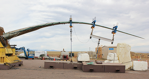
3TEX confirmed I-beam test results via static and fatigue testing on 13m /42.7-ft long commercial-type wind blades. Source: 3TEX
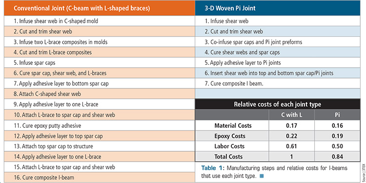
Table 1: Manufacturing steps and relative costs for I-beams that use each joint type. Source: 3TEX


Wind blades are commonly made by infusing top and bottom blade shells separately, then adhesively bonding them together around a prefabricated shear web. The current state of the art leaves much to be desired. The typical construction is essentially an I-beam, in which a C-shaped shear web provides an area for adhesive bonding to spar caps that are co-infused with the blade shell. Typically, the C-beam must be braced with additional L-beams during assembly (see left side of the illustration in the second image from top). After epoxy paste adhesive is applied to the bottom blade half and the shear web, their surfaces are mated, and sufficient time must be allowed for cure. Then, adhesive is applied to the top blade half, the upper surface of the shear web and the leading and trailing edges. Again, the adhesive surfaces are mated, and time is required for cure. This multistep process requires significant labor and time. Additionally, when the top half of the blade is lowered onto the bottom half, the joints are mated blindly, that is, without visual or other access to the bonding areas. Industry presentations and patents list other shortcomings and clearly state that blade designs would benefit from an improved bond configuration between the shear web and spar cap.
Textile manufacturer 3TEX (Cary, N.C.) began work on such a configuration several years ago as part of a Small Business Innovation Research (SBIR) project awarded by the U.S. Department of Energy (DoE, Washington, D.C.), using the Pi joint concept that was demonstrated in the Air Force Research Lab’s (AFRL, Dayton, Ohio) Composites Affordability Initiative (see “The Composites Affordability Initiative, Part I” under "Editor's Picks," at top right).


Why Pi?
3TEX cites two reasons for its use. First, the Pi joint (so named because its primary component takes the shape of the Greek letter π) have been shown in the aerospace industry to provide superior strength in pull-test loads, compared to conventional laminated joints. AFRL’s Dr. John Russell says the joint “provides symmetrical loads to the adhesive area and acts as a double lap-shear joint, increasing the surface area for bonding.” Also, the primary load in the adhesive bonds is located farther away from the area of maximum strain. These factors combine, says Russell, to make the Pi joint a more effective design. Pi joints also have demonstrated high tolerance of several manufacturing defects associated with blind mating, including excessively thick bondlines, voids, nonvertical alignment of the Pi legs or joint structure within the Pi, and even peel plies that are not removed before bonding.
Second, a Pi joint, despite its complexity, can be preformed in an automated process. 3TEX R&D director Dr. Keith Sharp says his company’s 3D Weaving process “lends itself to easy manufacture of Pi joint preforms. We simply design a textile with z-direction yarns penetrating completely through the thickness for the center portion and then only halfway through the thickness for the outer edges, allowing these lengths to be folded up to form the two legs of the Pi.” The dry preform is reportedly easy to co-infuse with the blade shell so the legs of the Pi align vertically to receive and locate the shear web. This permits the blade manufacturer to use a simple flat plate for the web — C-shapes and L-braces are no longer necessary. Therefore, blind mating of the joint surfaces is vastly simplified.
Pi progress
In a presentation at the 2012 SAMPE conference in Baltimore, Md., 3TEX reported that preliminary performance testing was done by fabricating composite I-beams made with the 3TEX 3-D woven Pi preform joint and a conventional joint (C-beam plus L-shaped braces, see top images, this page). The I-beams were 2.7m/8.9-ft long by 0.3m/1-ft tall, with 0.2m/0.7-ft wide flanges, matching the dimensions of the spar cap width and thickness and the shear web height of a 13m/42.7-ft long commercial wind blade at the 10m/33-ft station. The flanges were 8.1-mm/0.3-inch thick E-glass/epoxy laminate. A test apparatus was developed that clamped a standard I-beam at one end and applied an upward load at the other end to simulate the dominant type of loading on a wind blade.
For the Pi joint I-beams, Pi preforms were woven as a single E-glass fabric and split to form two 4.2-mm/0.2-inch thick legs, each measuring 42.5 mm/1.7 inches in length and separated by an 8.1-mm/0.3-inch thick central section that was 25-mm/1-inch wide. The 110-mm/4.3-inch wide preform had 54 percent total fiber volume fraction with equal amounts of fiber in both in-plane directions and 1.5 percent in the z-direction. A 20-mm/0.8-inch wide flat plate shear web was made, using 3.8-mm/0.2-inch thick faceskins of triaxial E-glass fabric from SAERTEX USA LLC (Huntersville, N.C.) on each side of a 12.4-mm/0.5-inch thick balsa wood core, supplied by distributor LBI Inc. (Groton, Conn.). The Pi joints and web were infused with Rhino 1401-21/4101-21 epoxy resin supplied by Rhino Linings (San Diego, Calif.). When the Pi joints and web were bonded, the Pi joint slot was 2.5 mm/1 inch wider than the web to allow sufficient space for the Rhino 405 Structural Epoxy Gel adhesive.
The conventional I-beam used in the test replicated the construction of a 13m/43-ft long commercial wind blade from Heartland Energy Solutions (Mount Ayr, Iowa). The C-shape shear web was made with two faceskins of triaxial E-glass fabric (0˚/±45˚ with 0˚ oriented along the beam length), each measuring 3.8-mm/0.15-inch thick, on each side of a 12.4-mm/0.5-inch thick balsa wood core. The material suppliers and infusion process were the same as those previously described. The top and bottom flanges of the C-beam were formed by extending the two faceskins at 90o to the cored section. The C-beam measured 7.6-mm/0.3-inch thick, and its height was 50 mm/1.97 inches. Two 7.2-mm/0.28-inch thick L-beams were adhesively bonded to bolster the C-beam. Spacers held the bondline thickness to 3 mm, ±0.3 mm (0.1 inch, ±0.01 inch).
Sharp says three conventional joint beams and five Pi joint beams were tested at the Constructed Facilities Laboratory at North Carolina State University (Raleigh, N.C.). The Pi joint beams failed at an average 12 percent higher load and 20 percent higher deflection than the conventional beams. That differed slightly from SAMPE paper data: “Those results included only three of the Pi joint tests and one of those underwent hysteresis loading. When we tested additional Pi joint cantilever beams without the hysteresis loading, the averages increased for both load and deflection at failure.”
Notably, the failure in the Pi joint beams resulted from buckling in the shear web, not failure in the Pi joint. The buckling forced the vertical legs of the Pi joint outward and, in turn, caused failure in the adhesive layer. Sharp asserts that increasing the shear web’s buckling resistance would likely produce an even higher failure load. However, this is not the case for the conventional joint beams, in which failure occurred within the adhesive layer first without any onset of buckling. Not least, the Pi joint beams also cost approximately 15 percent less to produce (see Table 1, last image). Sharp sums up, “Manufacture using co-infused 3-D woven Pi joint preforms requires fewer steps, less fiber, less resin and less adhesive than conventional joint manufacturing.”
Testing was extended to commercial-type construction of 13m blades. One blade with each joint type was tested under static load. Another pair was fatigue tested. Under static load the Pi-jointed blade failed at a 20 percent higher load and 25 percent greater deflection than the conventional blade. Even more dramatic were the results of fatigue tests. The test cyclically loaded the blades to 100 percent of the test load (design load plus a factor) for 1 million cycles, then it increased the load by 20 percent for each 200,000 cycles until failure. The blade with the conventional joint failed during the 160 percent load step after 1.45 million cycles. The Pi joint blade surpassed this, withstanding more than 700,000 cycles at the 180 percent load step; it failed after a total of 2.5 million cycles.
Pi potential
Sharp believes the 3TEX-tested Pi joint design could reduce the weight, cost and need for repairs in wind blades. “By increasing the ultimate strength and fatigue life, this type of joint should permit designers to reduce the material in the loaded sections of the blade, lowering material and manufacturing costs.” Indeed, 80m to 100m (262-ft to 328-ft) long blades now under development for offshore turbines might soon benefit from Pi joints (click on “Blade Dynamics receives investment for new wind blade design,” under “Editor's Picks").
Further, integrating Pi joints into blade construction methods appears to be a solution because increasing blade lengths tests the limits of current bond technology. During their discussion of design drivers and expected failure modes in future longer blades at the 2012 Sandia Wind Turbine Workshop (May 31-June 1, Sandia National Laboratories, Albuquerque, N.M.), representatives of Bladena (Ringsted, Denmark) pointed out that when the blade length surpasses 60m/197 ft, fatigue failure in the bondlines and failure of the shear web become a critical failure mode, a reality that could be addressed with Pi joints. Bladena, a commercial spin-off of wind energy research institute Risø DTU (Roskilde County, Denmark), also observed a nonlinear crushing pressure phenomenon that increases in longer blades because they bend more. The Pi-jointed beams in the test blades exhibited increased stiffness, which would counter the crushing pressure. Finally, Bladena identified interlaminar failure in the load-carrying spar caps and shear web flanges as a risk that increases with blade length. Orthogonally woven 3-D textiles are inherently resistant to delamination. Thus, they could improve performance not only in the shear web-to-blade shell joint but also in the spar cap. Therefore, Sharp believes Pi joint preforms could provide benefits elsewhere, especially in very large composite structures, such as those in ships.


.jpg;maxWidth=300;quality=90;format=webp)
Related Content

Materials & Processes: Resin matrices for composites
The matrix binds the fiber reinforcement, gives the composite component its shape and determines its surface quality. A composite matrix may be a polymer, ceramic, metal or carbon. Here’s a guide to selection.
Read More
Recycling end-of-life composite parts: New methods, markets
From infrastructure solutions to consumer products, Polish recycler Anmet and Netherlands-based researchers are developing new methods for repurposing wind turbine blades and other composite parts.
Read More
JEC World 2022, Part 1: Highlights in sustainable, digital, industrialized composites
JEC World 2022 offered numerous new developments in composites materials, processes and applications, according to CW senior editor, Ginger Gardiner, most targeting improved sustainability for wider applications.
Read More
JEC World 2022, Part 3: Emphasizing emerging markets, thermoplastics and carbon fiber
CW editor-in-chief Jeff Sloan identifies companies exhibiting at JEC World 2022 that are advancing both materials and technologies for the growing AAM, hydrogen, automotive and sustainability markets.
Read MoreRead Next

Market Trends: The Composites Affordability Initiative, Part I
The Air Force Research Laboratory's Dr. John Russell outlines the U.S. Department of Defense Composites Affordability Initiative. Part I of a two-part series.
Read More
Composites end markets: Energy (2024)
Composites are used widely in oil/gas, wind and other renewable energy applications. Despite market challenges, growth potential and innovation for composites continue.
Read More
CW’s 2024 Top Shops survey offers new approach to benchmarking
Respondents that complete the survey by April 30, 2024, have the chance to be recognized as an honoree.
Read More