The modified D695 compression test method
Dr. Don Adams discusses the evolution of the ASTM D 695 compression test method, the predecessor of the D 6641 method now in wide use.
Until the early 1970s, there was relatively little interest in measuring the compressive properties of composite materials. For design purposes, it was generally assumed that the compressive strength and modulus were similar to the tensile values. However, just as for aluminum some 30 years earlier, thin composite sheets were beginning to be used in aircraft structures, and more accurate knowledge of the compressive properties was needed.
Determining the compressive strength of a thin material specimen has been a long-standing challenge because the specimen tends to buckle prior to compressive failure. The use of thin aluminum sheet in aircraft construction during World War II motivated the development of suitable test methods. Government reports and journal articles from the 1940s contained very detailed presentations of various methods of laterally supporting a thin specimen without unduly influencing the axial compressive strength measurement. Candidates included lateral support of the specimen over its length with small-diameter rollers at both surfaces and using flexible metal fingers as well as the use of grooved plates and even lubricated flat plates. And rather than using just a single thin specimen, often a “pack” of specimens were stacked for testing. Sometimes, these stacked specimens were even lightly bonded for greater resistance to buckling. Eventually these techniques were included in the long-standing “Compression Testing of Metallic Materials,” ASTM E 9, first published in 1924 by ASTM International (W. Conshohocken, Pa.).
As interest in compression testing of thin plastic sheeting increased in the late 1930s and early 1940s, knowledge gained by the metals community was adopted, or adapted, to the extent possible. This led to ASTM D 695, “Compressive Properties of Rigid Plastics,” first issued in 1942. Grooved plates were selected as the lateral support method.
Obviously, when a compressive force is applied, the specimen decreases in length. If unloaded lateral supports, such as the grooved plates of ASTM D 695, are in contact with the surfaces of the specimen to prevent buckling, frictional forces along these surfaces will be generated by the relative motion. That is, some of the applied force passes through the lateral supports, making it appear that the specimen is stronger than it actually is.
Frictional force is the product of the coefficient of friction and the contact force. The coefficient of friction depends on the combination of materials in contact and, therefore, cannot be dictated because the test method is to have general applicability. And to prevent buckling, there must be a contact force between the specimen and the lateral supports. Thus, eliminating the reinforcing effect of the lateral supports is not possible. The only option is to minimize it, particularly by minimizing the clamping force exerted by the lateral supports on the specimen.
ASTM D 695 specifies that the clamping screws are to be “finger tight.” While not quantitative, this does at least suggest that a low clamping force should be used. The Boeing Co. (Seattle, Wash.) Specification Support Standard BSS 7260 is more specific, stating that the clamping screws are to be torqued to 0.6J to 1.0J (5 in-lb to 10 in-lb). The Suppliers of Advanced Composite Materials Assn. (SACMA) Recommended Method SRM-1 indicates 0.7J to 1.0J (6 in-lb to 10 in-lb). These values are quantitative indicators of “finger tight.” However, using this torque level is counterintuitive to many users. If a clamping force is required to prevent buckling, a heavy clamping force may seem better than a light force. More than one laboratory has fallen victim to this misconception.
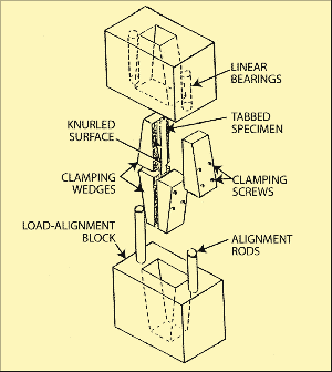
The first ASTM standard that specifically addressed compression testing of composite materials, the so-called Celanese compression test method, was published in 1975 as ASTM D 3410. But this was not a well-accepted test method, and the testing community soon began looking for alternatives. ASTM D 695 was a logical alternative. While primarily intended for unreinforced plastics, as its title suggests, this standard also is described as being applicable to reinforced plastics. But it uses an untabbed, dog-boned specimen. The specimen was dog-boned (i.e., increased in width at the ends) to provide increased bearing area for end-load introduction. However, composites experimentalists knew that the highly orthotropic materials they were working with could not be tested successfully using a dog-boned specimen. The “ears” at each end of the specimen would simply shear off during the test, reducing it to a straight-sided specimen that would then end-crush. Thus, a straight-sided specimen was used, with tabs bonded to each end to increase the load-bearing area.
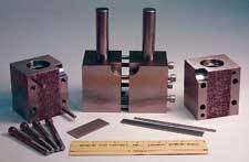
This straight-sided, tabbed specimen was used by a number of laboratories, with most of the credit for its development being given to Boeing, which included it in its test specification in 1988. The fixture is shown in the photo at right. Like others, Boeing also added a fixture base on which to mount the lateral supports to provide stability and greater ease of use. The test method has come to be called the Boeing Modified ASTM D 695 Compression Test Method, or simply the Modified D 695 Compression Test Method. Whether it is appropriate to call it a modification of ASTM D 695 is questionable because the specimen configuration is totally different. The only common features are the lateral support method and end-loading.
When the Modified D695 Compression Test Method was first developed for use with composite materials, it was intended primarily as a carbon/epoxy prepreg quality control test. To conserve material, a very thin (eight-ply) unidirectional composite specimen, typically about 1.0 mm/0.040 inch thick, was used. For that reason, a very short gage length (the central length between tab ends) was required to prevent buckling. A length of 4.8 mm/0.188 inch was selected. Ideally we want to measure both stress and strain simultaneously on the same specimen. But the small space between tabs in this method makes it very difficult to measure strain accurately and, thus, to determine modulus. It becomes necessary to lightly load a second, untabbed, strain-instrumented specimen, which significantly increases the total cost of data generation.
One minor, but interesting, feature is specimen length. The original metallic specimen test methods used a variety of lengths, most being in the 50-mm to 75-mm (2- inch to 3-inch) range. The plastic specimen of ASTM D 695 is 79.5 mm/3.13 inches long. The Boeing specimen is specified to be 79.5 to 80.8 mm/3.13 to 3.18 inches long, while the SACMA specimen is 80.8 mm/3.18 inches long. Why the Boeing specimen was allowed to vary in length so much (by 1.3 mm/0.050 inch) is not clear. But this certainly has created confusion within the industry. Typically, a specimen length of 80.8 mm/3.18 inches is now used, undoubtedly influenced by the SACMA method rather than ASTM D 695. SACMA first released SRM-1 in 1988. (SACMA was eventually disbanded in 2000.) Although ASTM considered adopting the test method in the early 1990s, that effort was never carried through. As a result, the Modified D695 Compression Test Method has become somewhat of an orphan — its popularity decreased considerably since the introduction in 2001 of ASTM D 6641, the Combined Loading Compression Test Method.
Editor's note: Dr Adams discussed the ASTM D 6641 method in two previous columns, listed in "Learn more" under "Editor's Picks," at right.
Related Content
Optimizing a thermoplastic composite helicopter door hinge
9T Labs used Additive Fusion Technology to iterate CFRTP designs, fully exploit continuous fiber printing and outperform stainless steel and black metal designs in failure load and weight.
Read MoreMaterials & Processes: Tooling for composites
Composite parts are formed in molds, also known as tools. Tools can be made from virtually any material. The material type, shape and complexity depend upon the part and length of production run. Here's a short summary of the issues involved in electing and making tools.
Read MorePlant tour: National Institute for Aviation Research, Wichita, Kan., U.S.
NIAR, located at Wichita State University in the heart of the American aerospace manufacturing industry, has evolved to become a premier hub of teaching, R&D, creativity and innovation.
Read MoreMulti-material steel/composite leaf spring targets lightweight, high-volume applications
Rassini International was challenged by Ford Motor Co. to take weight out of the F-150 pickup truck. Rassini responded with a multi-material steel/composite hybrid leaf spring system that can be manufactured at high volumes.
Read MoreRead Next
Testing cross-ply vs. unidirectional composites
Dr. Don Adams follows up his previous column on tensile testing with a discussion of such testing when confronted by two difficult-to-test laminate configurations.
Read MoreCurrent compression test methods
Dr. Don Adams discusses the test methods and fixtures currently available to test the compressive strength of composites.
Read MoreComposites end markets: Energy (2024)
Composites are used widely in oil/gas, wind and other renewable energy applications. Despite market challenges, growth potential and innovation for composites continue.
Read More





.jpg;maxWidth=300;quality=90)


