Testing cross-ply vs. unidirectional composites
Dr. Don Adams follows up his previous column on tensile testing with a discussion of such testing when confronted by two difficult-to-test laminate configurations.
In my previous column on tensile testing (see "Unidirectional composite axial tensile specimens," under "Editor's Picks," at right), I referenced a commonly expressed concern by Hart-Smith1 and others, when I wrote: "It is debatable whether one should even attempt a tensile test on a unidirectional composite, given the difficulties encountered, but that is a topic for another time." That topic's time has come.
While my previous column addressed tensile testing, the issue of using cross-ply laminates rather than unidirectional composites has become even more important for compression testing in recent years, as will be noted below. First, however, we need to define "cross-ply." Occasionally an article in the published literature does not distinguish between cross-ply and angle-ply laminates, referring to both as cross-ply laminates. However, it is more common to distinguish them. For our purposes, the former will be defined as a laminate with all plies oriented at 0° and 90°, i.e. a [0/90] family of laminates with arbitrary numbers and distributions of 0° and 90° plies. An angle-ply laminate is one containing off-axis plies of other orientations. Here, I will address the issues involved for both tensile and compressive loading, noting in particular that, by definition, a cross-ply laminate will fail at a lower applied force than a unidirectional composite of the same thickness, 90° plies being weaker than 0° plies.
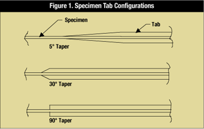
For tensile loading, the issues involved in testing unidirectional composites were discussed in detail in my previous article. In summary, it is difficult to adequately grip a high-strength tensile specimen. Detrimental stress concentrations are induced by the clamping action of the grips, and/or by the tabs used to cushion the effects of the grips. If the required gripping forces can be reduced, e.g., by reducing the applied forces required to fail the specimen, the local stresses are reduced.
For compression testing of unidirectional composites, the same problems may exist, possibly along with others, depending upon the type of loading used. Either shear- or end-loading, or a combination of the two, can be used, as I discussed in detail in a previous column on compression testing (see "Current compression test methods," under "Editor's Picks"). For shear loading, specimen tabs and wedge grips are commonly used, thus introducing the same stress concentration problems as for tensile testing. For end-loading, minimal clamping force is required, but tabs are still needed, here to increase the load bearing area so that end crushing does not occur. Thus, stress concentrations are introduced due to the geometric discontinuities at the tab ends. Combined loading reduces, but does not eliminate, all of these problems.
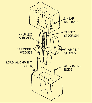
Ideally then, for either tensile or compressive loading, it is desirable to reduce, if not eliminate, the clamping forces, and to eliminate the tabs. The Wyoming Combined Loading Compression test fixture (see photo at right) and the corresponding ASTM Standard D 66412 were developed with exactly this in mind. The fixture was designed to test a straight-sided, untabbed, cross-ply specimen, using only enough clamping force to prevent end crushing. The fixture is shown partially disassembled to permit viewing of tungsten carbide particle-coated gripping surfaces used to increase the effective coefficient of friction between the specimen and the fixture, thus reducing the required clamping force to achieve a given shear-loading component.
But why would an ASTM test method be developed just to compression test cross-ply laminates? In fact, SACMA (Suppliers of Advanced Composite Materials Association) first issued SACMA Recommended Methods (SRM) for both tensile3 and compression4 testing cross-ply laminates in 1992, after considerable discussion in the literature, beginning in the mid-1980s.
SRM-9 was designed specifically for tensile testing a [90/0]ns cross-ply laminate (a symmetric laminate as indicated by the subscript s, with n, the number of pairs of 90° and 0° plies on each side of the mid-thickness of the laminate — typically three pairs, which results in a 12-ply laminate) and closely follows ASTM D 30395, using a 25.4 mm (1-inch) wide specimen. Since half of the plies in the laminate are of relatively low strength, the cross-ply laminate is much easier to test successfully than a unidirectional composite. But what is unique in SRM-9 is that a simple formula also is presented for calculating the unidirectional composite strength from measured cross-ply strength, by multiplying the latter by the following factor,
BF = 2E11/(E11 + E22)
where E11 and E22 represent the measured axial and transverse stiffnesses of the unidirectional composite. (Note that it is the unidirectional composite ultimate strength that is difficult to measure accurately. Stiffnesses can be measured at load levels well below ultimate.)
SRM-6, for compression testing a [90/0]ns cross-ply laminate (symmetric, with n typically equaling either three or six, depending on the areal weight of the plies), roughly followed ASTM D 6956, using the Boeing-Modified D 695 Compression Test Fixture and either a 15-mm or 0.50-inch wide specimen. A minimum specimen thickness is required to prevent buckling, something that is not a consideration for tensile testing. Again, the simple formula in the equation above was used to obtain a factor for calculating the unidirectional composite strength from the measured cross-ply laminate strength. This factor has come to be called the Back-out Factor, since the unidirectional composite strength is "backed-out" of the cross-ply strength experimental data. Thus, although this factor was designated as F in the SACMA documents, BF is more descriptive.
Actually, the Back-out Factor given in the equation is a very simplified approximation of the rigorous laminated plate theory equation and only applies to [90/0]ns laminates, i.e., symmetric cross-ply laminates containing equal numbers of 0° and 90° plies. In my next column (see "Back-out factors," under "Editor's Picks"), I will discuss more rigorous forms of this Back-out Factor, which will be applicable to other types of laminates as well. I also will present an example of how the Back-out Factor has been used with various types of laminates. This discussion will reinforce the conclusion that a [90/0]ns laminate is the logical choice for use in backing out unidirectional composite strengths.
References
1 Hart-Smith, L.J., "Backing-out Composite Lamina Strengths from Cross-ply Testing," in Comprehensive Composite Materials, A. Kelly and C. Zweben, editors, Elsevier Science Publishers (Oxford, U.K.), 2000, pp. 149-161.
2 ASTM Standard D 6641-01, "Determining the Compressive Properties of Polymer Matrix Composite Laminates Using a Combined Loading Compression (CLC) Test Fixture," ASTM International (W. Conshohocken, Pa.), 2001 (first issued in 2001).
3 SACMA SRM 6-94, "SACMA Recommended Test Method for Compressive Properties of Oriented Cross-Plied Fiber-Resin Composites," Suppliers of Advanced Composite Materials Assn. (Arlington, Va.), April 1994 (first issued as SRM 6-92 in 1992).
4 SACMA SRM 9-94, "SACMA Recommended Test Method for Tensile Properties of Oriented Cross-Plied Fiber-Resin Composites," Suppliers of Advanced Composite Materials Assn. (Arlington, Va.), April 1994 (first issued as SRM 9-92 in 1992).
5 ASTM Standard D 3039-00, "Test Method for Tensile Properties of Polymer Matrix Composite Materials," ASTM International, (W. Conshohocken, Pa.), 2000 (first issued in 1971).
6 ASTM Standard D 695-02a, "Compressive Properties of Rigid Plastics," ASTM International (W. Conshohocken, Pa.), 2002 (first issued in 1942).
Related Content
Materials & Processes: Fabrication methods
There are numerous methods for fabricating composite components. Selection of a method for a particular part, therefore, will depend on the materials, the part design and end-use or application. Here's a guide to selection.
Read MoreNovel dry tape for liquid molded composites
MTorres seeks to enable next-gen aircraft and open new markets for composites with low-cost, high-permeability tapes and versatile, high-speed production lines.
Read MorePEEK vs. PEKK vs. PAEK and continuous compression molding
Suppliers of thermoplastics and carbon fiber chime in regarding PEEK vs. PEKK, and now PAEK, as well as in-situ consolidation — the supply chain for thermoplastic tape composites continues to evolve.
Read MoreMaterials & Processes: Composites fibers and resins
Compared to legacy materials like steel, aluminum, iron and titanium, composites are still coming of age, and only just now are being better understood by design and manufacturing engineers. However, composites’ physical properties — combined with unbeatable light weight — make them undeniably attractive.
Read MoreRead Next
Unidirectional composite axial tensile specimens
Dr. Don Adams explains why the design of tensile test coupons is more art than science, and explains the implications of that art for testing accuracy.
Read MoreCurrent compression test methods
Dr. Don Adams discusses the test methods and fixtures currently available to test the compressive strength of composites.
Read MoreCW’s 2024 Top Shops survey offers new approach to benchmarking
Respondents that complete the survey by April 30, 2024, have the chance to be recognized as an honoree.
Read More




.jpg;maxWidth=300;quality=90)

