
Tailored Fiber Placement: Besting metal in volume production
Affordable automated production of highly optimized preforms and parts.

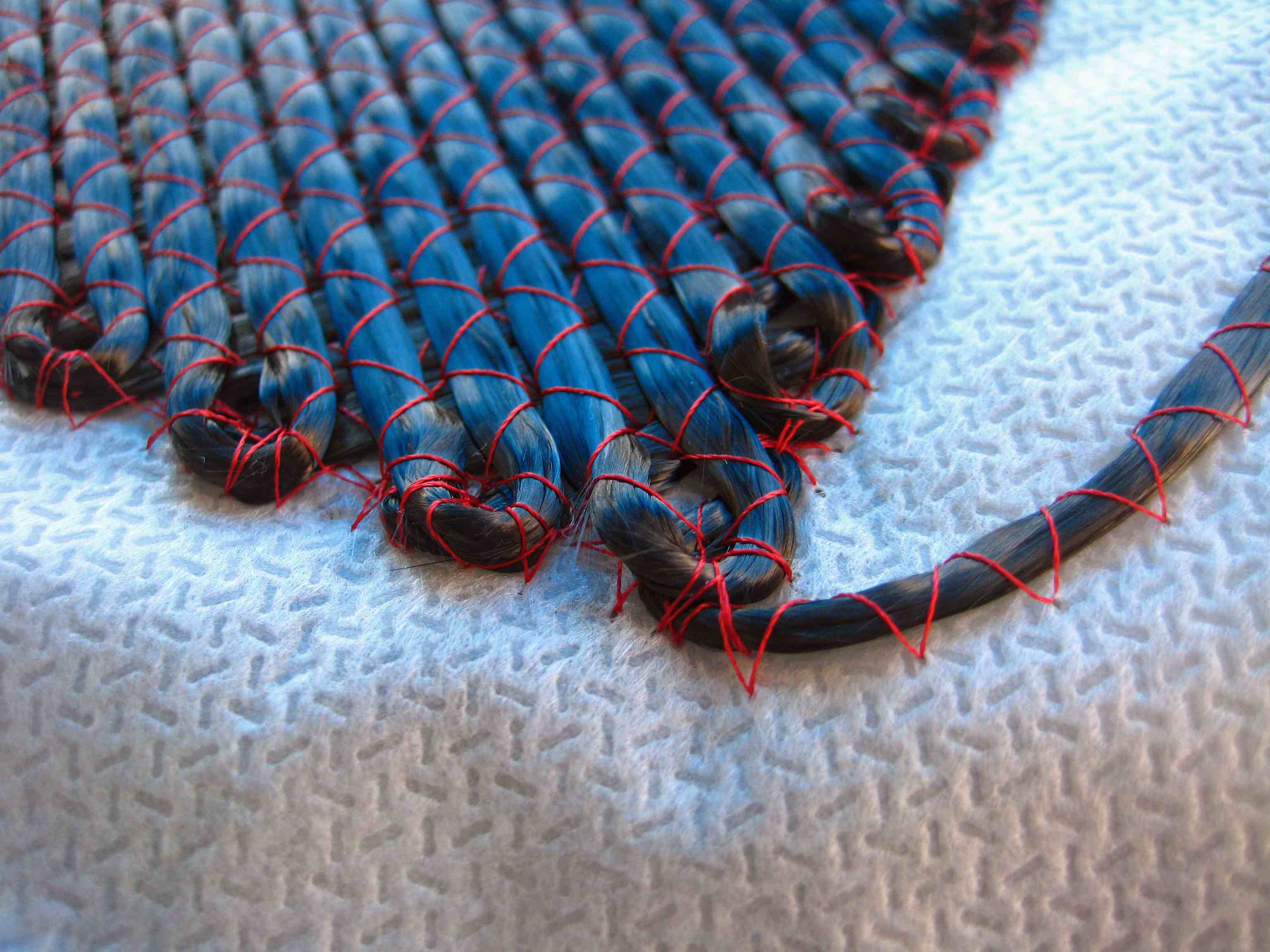
Tailored Fiber Placement TFP can quickly construct complex, optimized fiber preforms that maximize perfromance-to-weight. Here, a TFP system lays 50K tow at the same speed it can lay 3K tow, without the processing difficulties that heavy tow often causes in knitting or traditional weaving processes. Source: Laytstitch
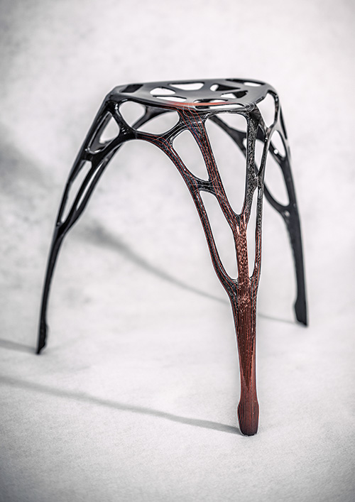
Leibniz Institute of Polymer Research (IPF, Dresden, Germany), the inventors of TFP, produced the preform for this stool using the process. The stool weighs about 650g (roughly 300g of carbon fibers). Weight-bearing capability has been tested to 150 kg. Source: IPF
TFP fiber deposition speed is a product of many factors, including machine speed, number of stitches required, stitch length and tow size. Source: Laystitch

Table 1: The principal actors in the development of Tailored Fiber Placement.
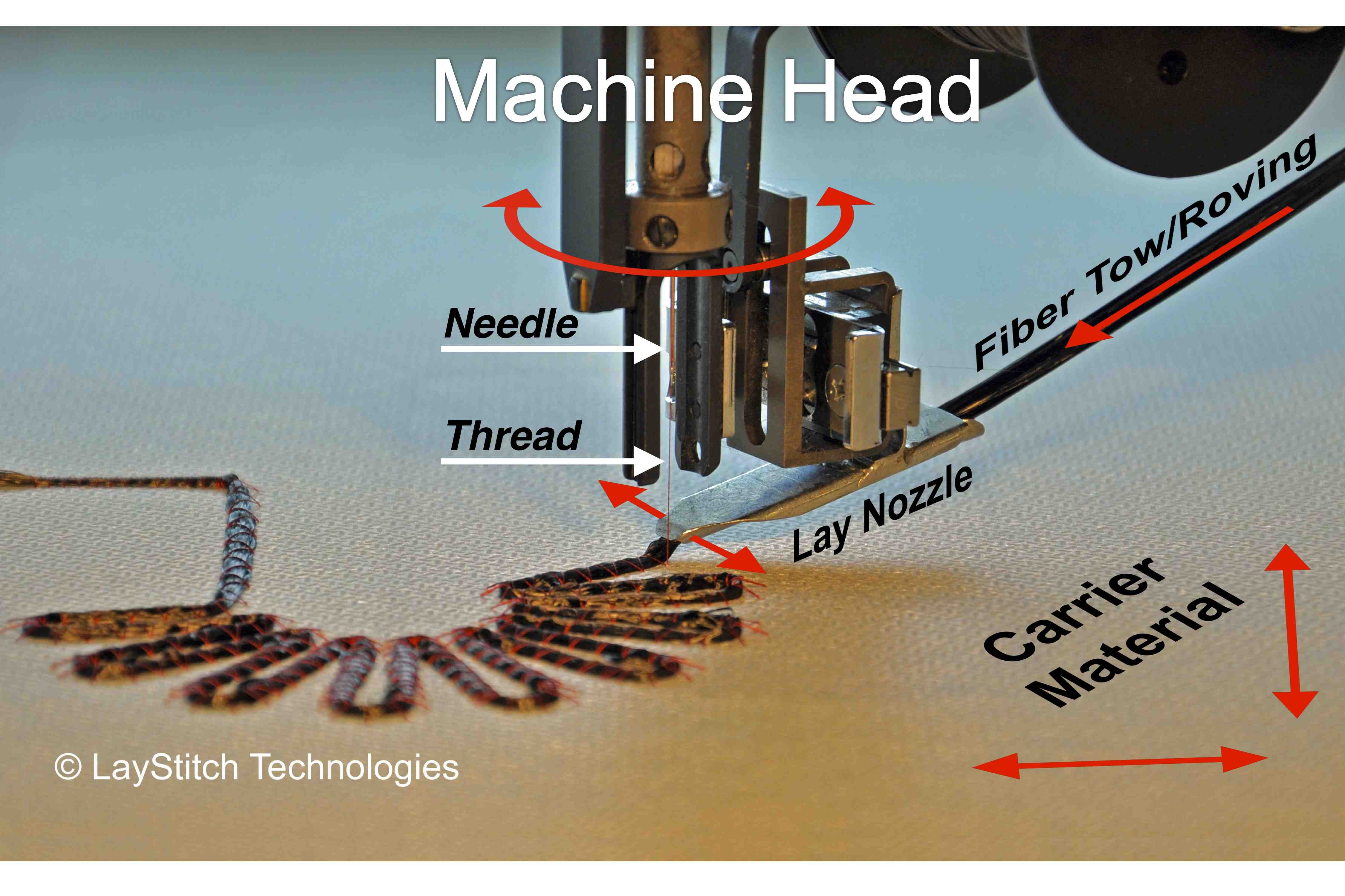
Fig. 1: Continuous tows or rovings can be placed in any direction by rotating the roving pipe and moving the base on which the veil or foil is placed. The roving is then stitched onto the base material to create the preform. Source: Laystitch
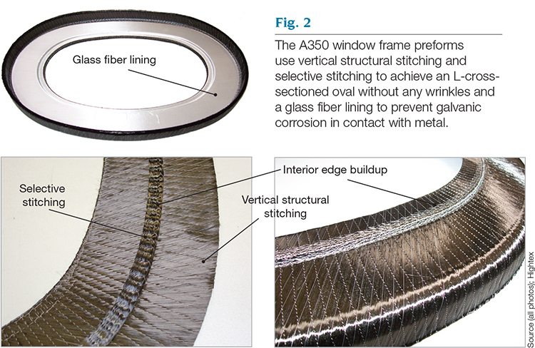
Fig 2: The A350 window frame preforms use vertical structural stitching and selective stitching to achieve an L-cross-sectioned oval without any wrinkles and a glass fiber lining to prevent galvanic corrosion in contact with metal. Source (all photos): Hightex
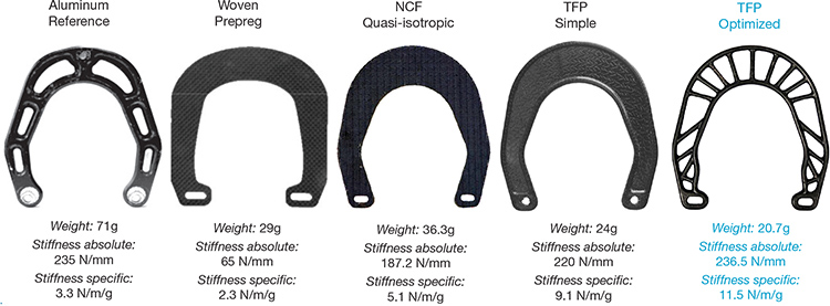
Fig. 3: Recently developed CAD tools enable optimized designs, like this for a bicycle brake booster part, that offer dramatic weight reduction and increases in specific strength and stiffness compared to other composites and light metals. Source: IFB Institute of Aircraft Design (Stuttgart, Germany)
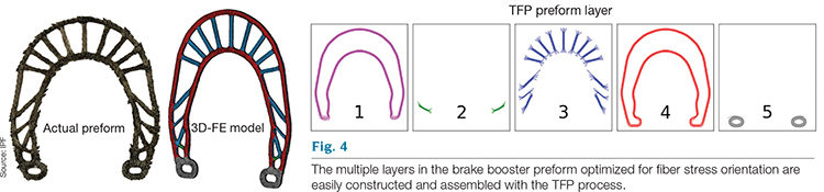
Fig. 4: The multiple layers in the brake booster preform optimized for fiber stress orientation are easily constructed and assembled with the TFP process. Source: IPF
Fig. 5a: Multiple TFP preforms were assembled into a 3-D preform (next photo) and then molded into a robotic arm linkage (photo after next). Source: Hightex
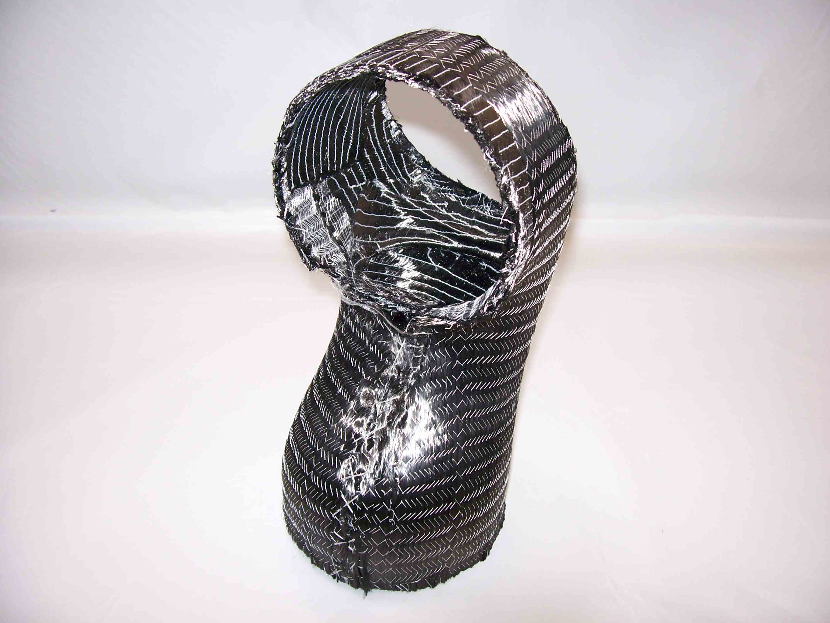
Fig 5b: Multiple TFP preforms were assembled into a 3-D preform (this photo) and then molded into a robotic arm linkage (next photo). Source: Hightex
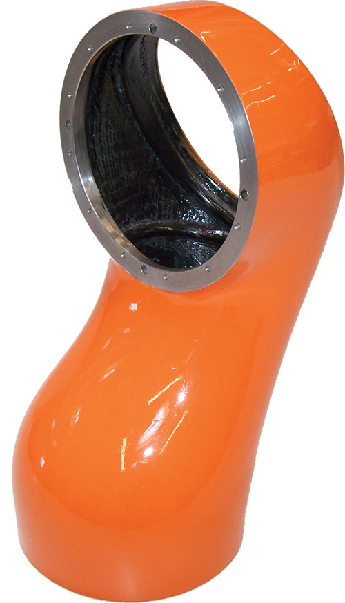
Fig. 5c: Multiple TFP preforms were assembled into a 3-D preform (previous photo) and then molded into a robotic arm linkage (here). Source: Hightex
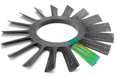
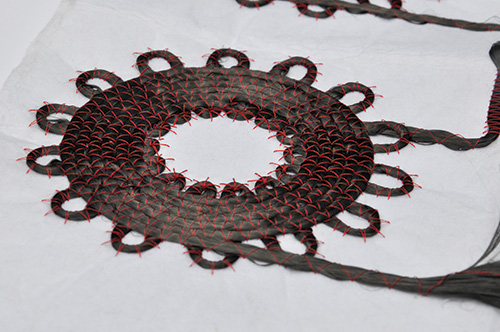
Fig. 6a: This one-piece CFRP vacuum rotor was the result when an optimized radial and tangential fiber placement pattern (see next two images) were used to achieve 35 percent higher burst strength than common high-strength aluminum designs. Source: IPF
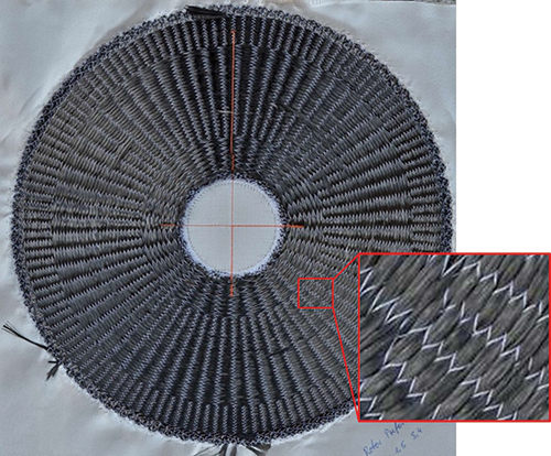
Fig. 6b: The preform used in the CFRP vacuum rotor (see photo above. Source: IPF
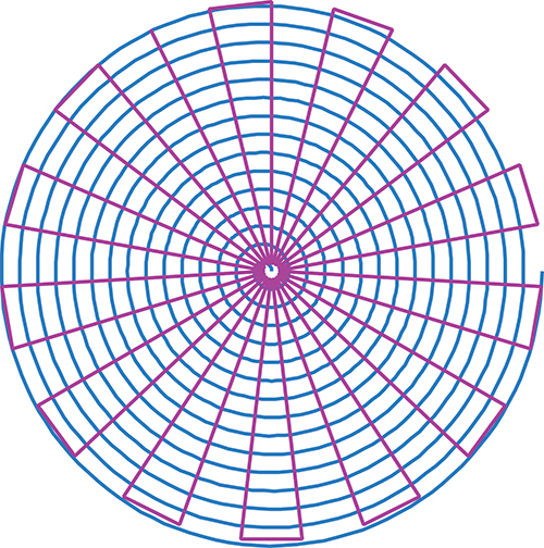
Fig 6c: The optimized radial and tangential fiber placement pattern used to make the TFP preform for the CFRP vacuum rotor (see the previous two images). Source: IPF


In the quest for more automated, less costly advanced composite manufacturing, liquid molding processes are finding favor. Among automotive composites researchers, for example, at least one group claims to have developed a resin transfer molding (RTM) process that has a 60-second molding cycle. No less important, however, is the need for an equally fast process for fabricating the dry preform. Complicating the quest is the fact that those who make preforms can no longer rely on quasi-isotropic laminates with local reinforcements if they are to compete with the latest in metals technology. In fact, advancements in computer-aided design (CAD) have enabled composite structural designs that offer more than 50 percent weight savings vs. lightweight metals, as well as a threefold increase in specific strength and stiffness. The question is how to affordably, reliably and quickly fabricate the resulting complex shapes that depend for their performance in the finished part on minimal quantities of precisely oriented fibers. Tailored Fiber Placement (TFP) is a unique stitched preforming process that could offer the answer.


Affordable optimized structures
Many have pursued TFP development (see Table 1) but it was invented at the Leibniz Institute of Polymer Research (IPF, Dresden, Germany) in 1992. TFP begins with a substrate, typically a veil or woven fabric, or, for a thermoplastic composite, a matrix-compatible foil material. Continuous tows or rovings are placed precisely and stitched to the substrate. The process is automated, enabling high productivity and repeatability. At first, the stitching was done with industrial embroidery machines, but TFP now uses purpose-built stitching machines to place continuous tows or rovings in any direction by rotating a stationary stitching unit and using computer numerical control (CNC) to move the substrate (see Fig. 1).
Although a variety of contoured and 3-D weaving techniques were developed in the same time period and, like TFP, use through-thickness reinforcement and stitching to overcome interply delamination and permit the preform thickness, shape and fiber orientation to be customized, TFP sprang from a different motivation: Its inventors wanted to mimic lightweight structures in nature (e.g., trees, grasses and bones) whose geometries are optimally adapted to specific loads. Called biomimetics, it is a growing trend in aircraft structural design. Its goal is to achieve the best possible mass-specific stiffness and strength by orienting fibers in the principal stress directions. In computerized structural design, topology optimization was developed to achieve this outcome. When an initial part design and its load cases are input, topology optimization software will output a shape and optimize material placement to produce a homogeneous stress distribution (that is, a structure in which there are no stress concentrations) with the least amount of material.
For composites, it has been difficult to manufacture cost-effective topology-optimized structures because they are typically 3-D geometries with unconventional fiber orientations. TFP machines, however, can manufacture multiaxial reinforcements of many plies, to many thicknesses, with precise and complex fiber architectures. They do so because they can place dry fiber in almost any orientation and can build up a wide range of composite constructions that are not feasible with standard unidirectional and mutiaxial laminates. To distinguish this more complex capability, TFP’s advocates like to call it fiber printing. The resulting dry fiber preforms can be processed using either RTM or vacuum-bag resin infusion. Molders also may use flexible thermoplastic towpreg or commingled tow and thermoplastic filaments (the latter melt and become the matrix). These thermoplastic preforms can be processed into finished parts via compression molding, or they may be used as inserts in injection molding.
2-D to 3-D, wrinkle-free
TFP patterns are printed flat but are designed to be easily fashioned into 3-D net-shape preforms. One way to achieve this is to use selective stitching, that is, to lay fiber out over a specific length without stitching. This results in areas of the preform where the fiber is not restricted by stitching and, thus, is free to move in any direction to facilitate shaping the final 3-D preform without wrinkles or distortions in fiber alignment.
A notable example of the effectiveness of this technique is the Omega Frame, a curved fuselage-type frame with a cross-section shaped like the Greek letter Ω, developed by Hightex Verstärkungsstrukturen (Klipphausen, Germany) with the Airbus (Toulouse, France) operation in Hamburg, Germany. Dr. Dick Feltin, managing director at Hightex, says, “Selective stitching combined with an unusual TFP fiber pattern made each 2-D preform stretchable and easily formable into its final 3-D-shaped U-structure.”
Currently in production are Airbus Hamburg’s A350 XWB carbon composite window frames, also developed with Hightex. They feature both selective stitching and structural stitching (straight up and down stitches) and a glass fiber lining on the inside to prevent galvanic corrosion with aluminum interfaces (see Fig. 2. The flat TFP preforms are then shaped into a wrinkle-free oval with an L-shaped cross-section. Selective stitching allows fibers to reshape easily yet maintain straight alignment. Structural stitching assists in handling loads around the circumference of the window frame. Feltin adds that with TFP, drapeability can be augmented by designing stitch lines wisely and, he notes, “You can avoid openings in the fiber intersections, which are common in traditional woven and knit reinforcements.”
The TFP preform’s net shape also eliminates the material waste common to other preforming processes, but Tommy Fristedt, president of LayStitch Technologies (Highland, Mich.), the U.S. affiliate of long-time TFP development and marketing company FilaCon (Winterlingen, Germany), notes that there’s more: “With knitting and weaving, a lot of material is wasted in the final structure due to the textile machinery’s limitations as to what direction you can orient the fibers,” he explains. “TFP does not have these limitations and, thus, can place fiber only where it needs to be.” He adds that carbon fiber purchased as woven material for other preforming processes can cost three to five times more per pound than the unconverted tow used in TFP. “Combine this with the 30 to 50 percent waste common to most textile-based composite processes and there is a lot of money to be saved in producing CFRP structures.”
Automating the design process
TFP’s ability to provide a solution was recognized immediately, but the design process was sophisticated and complex, so applications were limited. “In the past,” says Fristedt, “TFP machines were quite slow and design was very manual and time-consuming, but now software has been developed that allows the user to convert a CAD file into a stitch pattern optimized for manufacturability.”
Fristedt credits IPF with strategies for optimizing fiber orientation and for developing better design tools, including Advanced Optimisation for Principal Stress (AOPS). Originally based on the ANSYS finite element (FE) software (supplied by ANSYS Inc., Canonsburg, Pa.), AOPS now features other FE solvers and internal material optimization capabilities, as well as the ability to extrude traditionally 2-D finite elements in the computer model to local thickness and maintain fiber orientation.
“We needed a method to generate computer models where we could adapt thickness and fiber orientation per element,” explains IPF researcher and AOPS codeveloper Axel Spickenheuer. AOPS now makes it possible, he says, to calculate these extremely complex fiber orientations. Fig. 3 shows the dramatic weight reduction and specific stiffness increase possible for a mountain bike brake booster component when an AOPS TFP-optimized preform design is used instead of one that features aluminum or quasi-isotropic composites. The multiple layers and easily achieved stitch patterns used can be seen in Fig. 4.
TFP-optimized designs also show increased failure loads in open-hole tensile tests. Spickenheuer notes, “In testing, the TFP part does not fail at the hole as would be expected, but instead fails like a part that has no hole. In other words, the TFP orientation … actually increases open hole failure loads up to 50 percent.”
Consistency, repeatability, adaptability
TFP’s advanced design software and automated functions ensure high accuracy and repeatability in the quantity and orientation of fiber deposition. The benefit of this is illustrated in longerons developed by Hightex and Eurocopter (Donauwörth, Germany) for NHIndustries’ (Aix-en-Provence, France) NH-90 helicopter. These I-beam shaped structures were built up by combining multiple TFP preforms to form the central load-carrying longitudinal in the vehicle, distributing lift from the rotor to the rest of the structure, and also supporting the engine mounted on top. Made with aerospace-grade carbon fiber, the TFP preforms exhibit very low mass variation. As a result, the breaking load values remain within a 1 percent spread. Feltin points out, “The only way to do this is if you have very consistent fiber orientation within the part.”
TFP also enables engineers to incorporate a resistive self-heated layer, which is an obvious aid to cure in composite tooling, and it can ensure through-cure in the part. For example, a robotic arm was developed by Hightex using a very lightweight biomimetic design that emulated an insect-like exoskeleton. The multiple flat TFP preforms that were assembled into the 3-D preform for an arm linkage included a built-in carbon fiber heating element (Fig. 5). During the RTM process, electrical current was passed through the element to speed and improve the cure of the epoxy matrix. IPF recently completed a project with Airbus on composite structures with integrated heating capability for de-icing and anti-icing applications. This work has moved on to IPF spinoff Qpoint Composite (Dresden, Germany), whose other customers include FACC (Ried im Innkreis, Austria), Audi (Ingolstadt, Germany), Daimler (Stuttgart, Germany), Lamborghini (Sant’Agata Bolognese, Italy) and Premium AEROTEC GmbH (Augsburg, Germany).
Limitations and applications
Fristedt explains that TFP performs best at a smaller scale — the frame size or lay area for each sewing head can be up to 2m by 1.75m (6.56 ft by 5.74 ft). Although machines are routinely made with multiple lay heads, preforming an entire wind turbine blade or aircraft fuselage panel with a single machine would be impractical. And to take full advantage of TFP, Spickenheuer advises that parts should not have too many load cases: “For example, large fuselage sections have a large array of loads and loading conditions. TFP performs well in parts that have a more narrow set of specific loads.”
“TFP’s biggest problem is the stitching thread,” Spickenheuer adds. “We use really thin thread — only 2 to 3 percent by weight of the whole preform — but still, it creates micro-holes, which create resin concentrations when the preform is impregnated.” This can be an issue, especially in structures that undergo cyclic loading, because it can introduce microcracking. But Spickenheuer points out, “This is also an issue for noncrimp and woven fabrics.” Nevertheless, TFP has proven to be the best technology for structures like the A350 window frames, he says. “These do undergo cyclic loading, but with careful design, the resin concentrations have been minimized, and the technology has performed well.”
If the ideal TFP application isn’t a large fuselage section, then what is? In aerospace, targets include levers for aircraft vertical stabilizers and aircraft landing gear devices. Spickenheuer points also to “fast-moving machinery, such as robotic arms and levers that are moved quickly and often.” The less fiber-intensive preform reduces mass and improves arm speed, and less weight permits the use of smaller gears and motors. “It also increases the arm failure load,” Spickenheuer notes.
The latest project for Spickenheuer’s team illustrates another application: a one-piece, carbon fiber composite vacuum pump rotor with 17 blades integrated into the disk. The use of a TFP preform with an optimized combination of radial and tangential fiber orientations (Fig. 6) achieved a 35 percent higher burst speed than can be obtained with common high-strength aluminum designs. The vacuum-assisted, resin-infused part achieves a significantly higher operating speed due to reduced mass. Composites offer one of the few avenues to obtain such improvements, due to the limited mass-based tensile strength of lightweight metallic alloys. Spickenheuer believes even greater improvement is possible by employing further TFP optimization and sees widespread applications in high-speed impeller rotors, aircraft engines and other compressor fans.
Automotive speeds?
Fristedt points beyond aerospace to potential automotive applications — suspension parts, brackets, crash cones, chassis parts, pillars, door lock hinges, seat frames, instrument panel parts, bumper frames and the like — but admits that the TFP designs and production approaches now used in aerospace would be inappropriate for automotive.
To be sure, TFP is already quite sophisticated. According to Stefan Carosella, head of the Composites Group for the Institute of Aircraft Design (IFB) at the University of Stuttgart, machine manufacturers have improved TFP automation and productivity by developing automated base material transport, automated frame change out that allows continuous production and an endless feeding device that enables the use of standard roving spools (about 8 kg of roving vs. small spools at only 90g each).
LayStitch claims TFP preform design and adjustment is easier and faster with its new Automated Design Software. After the design is made it can be instantly printed in the laying machine. Spickenheuer says IPF has improved TFP via its AOPS software for preform design and EDOpath machine control software, but he admits, “There is still much work to do to make TFP more competitive with the production rates of knitting and weaving machines.”
In short, machine speed is still limited. FilaCon quotes a maximum single-head TFP machine speed as 10m/min (30 ft/min). Carosella asserts that a mass of up to 1 kg/hr (2.2 lb/hr) is possible with a single-head machine. But he points out that the actual fiber deposition rate is a product of machine speed, stitch length and tow size. He says a typical deposition speed is between 2m/min and 5m/min (6.6 ft/min and 16.4 ft/min) and that stitch length averages between 3 mm and 5 mm (0.12 inch and 0.2 inch), increasing with UD and straight fiber deposition and decreasing with complex geometry. Fristedt notes that “Preforms designed to take advantage of heavier tows and stitch patterns optimized for speed will produce the fastest cycle times.”
Carosella points out that a TFP head can reach the 1 kg/hr rate only by using 50K tow. “If you use 12K tow, the output rate is only 0.3 kg/hr.” Fristedt adds that TFP can accommodate heavy tow — a likely fiber size in auto applications — without the processing difficulties the heavier fibers often cause in knitting or traditional weaving. “A 50K tow is laid at the same speed as a 3K tow, even in fairly intricate patterns,” he explains, “so using heavier tows achieves an overall weight and volume of fiber much more quickly. And we are continuing to develop new lay nozzles for heavy tows to improve the complexity and speeds possible.”
“TFP, however, is easily adaptable to automotive,” Fristedt says, noting that high annual production volumes of preforms are possible using multiple heads. “A TFP machine can have from 1 to 30 printer heads,” he claims. “In the time it takes to make one preform, a 30-head machine can make 30 preforms. Thus, production is quite scaleable.” Fristedt adds that a large, multiple-head TFP machine could be installed for under $300,000 — less than a typical automotive sheet metal forming tool — depending on preform size and complexity, 50,000 to 2 million parts per machine per year is possible.
Fiber placement future
All who work with it agree that there is an increasing awareness of TFP in the composites industry. “Especially in the U.S., companies recognize the advantages it offers,” says Fristedt, particularly with thermoplastics. In fact, the latest U.S. machine went to the new Atlanta, Texas, headquarters of prepreg supplier Fibrtec.
“TFP offers benefits with thermoplastics above and beyond what it achieves with thermosets,” says Fibrtec CEO Bob Davies. “Our patented FIBRFLEX is unique in that it is flexible, and thus very amenable to the TFP process. The resin is already there, surrounding the fibers, so once we reach the melt point, we can push the preform into the mold extremities and achieve a very complex shaped part quickly with excellent resin-to-fiber distribution.”
Davies notes that a thermoplastic TFP preform can be used as an insert in an injection mold: “The parts manufacturer can use a FIBRFLEX tow coated with Nylon 6,6 — a common matrix used in automotive — and then inject Nylon 6,6 overtop of that preform.” This enables production of fiber-reinforced structural parts with intricately shaped ribs, bosses or connectors on multiple surfaces — something too difficult to achieve cost-effectively with other composites. The result is a homogeneous matrix throughout, without bondlines.
Fibrtec is pursuing large- and small-volume structural automotive and aerospace applications and sees commercialization possible in as little as six months. LayStitch Technologies is working with Fibrtec on a study that will compare the cost, weight and property improvements possible in structures using a thermoplastic TFP preform vs. metal and thermoset composite alternatives, similar to the IPF/Hightex bicycle brake booster.
IPF has completed work on the German government-funded highSTICK project, with 26 other companies, aimed at gaining technical leadership in integrated high-performance materials based on advanced textile manufacturing, especially for small batches and custom parts. It is now in a follow-on phase. Development areas include embroidered strain sensors and lighting systems, “functionalized prepreg,” “wire embroidery,” 3-D hybrid structures for thermoplastic composites and more flexible, modular embroidery machines.
TFP, Fristedt sums up, is “enabling customers to imagine an innovative solution, design it and then economically produce it.”


Related Content

CAMX 2022 exhibit preview: Parabeam
Parabeam’s 3D E-glass woven fabrics, particularly ParaGlass and ParaTank, continue to advance composite sandwich structures with high flexibility, strength and application versatility.
Read More
Materials & Processes: Fabrication methods
There are numerous methods for fabricating composite components. Selection of a method for a particular part, therefore, will depend on the materials, the part design and end-use or application. Here's a guide to selection.
Read More
PEEK vs. PEKK vs. PAEK and continuous compression molding
Suppliers of thermoplastics and carbon fiber chime in regarding PEEK vs. PEKK, and now PAEK, as well as in-situ consolidation — the supply chain for thermoplastic tape composites continues to evolve.
Read More
Biteam introduces 3D Noodle International AB spin-off for 3D fabric noodles
Biteam 3D’s third spin-off implements its proprietary 3D weaving technology to produce a variety of carbon, ceramic and other fiber 3D fabric noodle preforms.
Read MoreRead Next

CW’s 2024 Top Shops survey offers new approach to benchmarking
Respondents that complete the survey by April 30, 2024, have the chance to be recognized as an honoree.
Read More
From the CW Archives: The tale of the thermoplastic cryotank
In 2006, guest columnist Bob Hartunian related the story of his efforts two decades prior, while at McDonnell Douglas, to develop a thermoplastic composite crytank for hydrogen storage. He learned a lot of lessons.
Read More
Composites end markets: Energy (2024)
Composites are used widely in oil/gas, wind and other renewable energy applications. Despite market challenges, growth potential and innovation for composites continue.
Read More