
SQRTM enables net-shape parts
New out-of-autoclave process combines resin transfer molding with prepregs for complex helicopter part prototype.

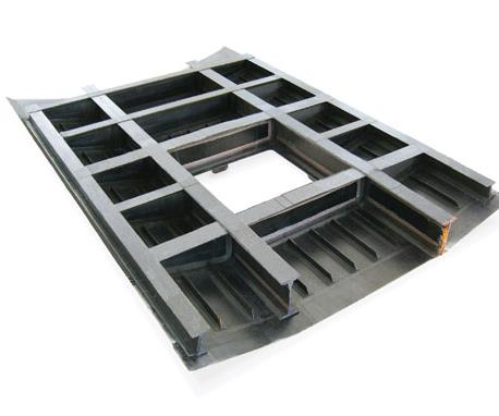
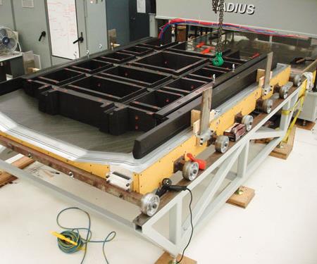
This net-shape unitized part, fabricated by Radius Engineering (Salt Lake City, Utah), is a prototype rotorcraft roof component produced as part of the SARAP (Survivable Affordable Repairable Airframe Program) initiative. This underside view of the ~250 lb/~120 kg “grid-stiffened” part shows its four thick, integrated longitudinal beams and several lighter perpendicular frames as well as the integral upper-skin stiffeners. Source: Radius Engineering
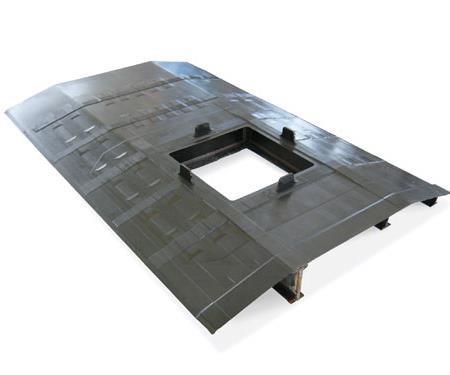
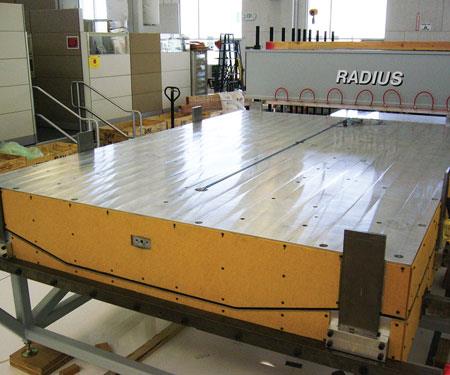
This top view of the finished roof shows the integral upper skin as well as the opening and integral supports for the rotor trans-mission. With rough dimensions of 9.5 ft by 6.2 ft by 1 ft (2.9m by 1.9m by 0.3m), the roof is combined with other fuselage components (see photo on p. 48). The roof section models a prospective method for reducing the fuselage part count and weight. Source: Radius Engineering
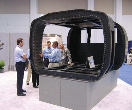
A completed SARAP fuselage prototype, on exhibit at a helicopter industry trade event. The SQRTM-fabricated roof component is visible as part of the assembly, which also includes other innovative composite designs. Sikorsky is reportedly considering the SQRTM technology for future helicopter manufacturing programs. Source: Radius Engineering
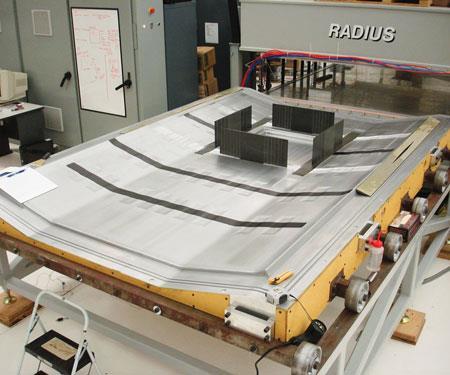
Step 1: Layup of the complex roof part, shown here in the early stages, involved placement of a combination of debulked prepreg materials and dry preforms (described in step 3) on the lower mold half. Source: Radius Engineering
Step 2: The roof skin’s prepreg layup is in place, and the network of tooling inserts that will form the faces of the roof section’s beams and perpendicular frames are in position. Source: Radius Engineering
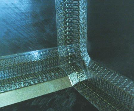
Step 3: This closeup shows the “pi” preforms used at the intersections of vertical and horizontal elements. Everywhere a vertical stiffener web meets a beam flange or the part skin, the two legs of the pi preform form a slot that accepts the web while the perpendicular preform element lays flat against the horizontal flange or skin. The preforms functioned to fill the radii between web and caps or flanges for each of the part’s numerous beams and frames. Source: Radius Engineering
Step 4: The layup has been completed, multiple tool inserts installed, and the mold closed. At this point, injection take place, using the same resin as that incorporated into the the prepregs, to maintain steady hydrostatic pressure within the mold. source: Radius Engineering
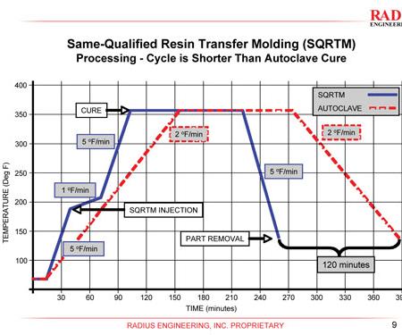
Step 5: After injection, cure begins. As this chart demonstrates, SQRTM enables faster processing, because the greater thermal conductivity of the press and tool permit faster heating and cool down. RTM cure can be two hours shorter than an autoclave cycle. Source: Radius Engineering
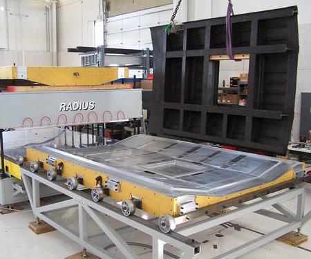
Step 6: A cured roof part is shown as it is lifted from the tooling base. Visible to the left of the tool is the heated platen press with upper and lower bolsters of welded steel, ground flat to high tolerance, that heat and clamp the tool. Source: Radius Engineering


The current trend toward out-of-autoclave (OOA) processing is driven by manufacturers’ competing needs to produce larger parts to help decrease fabrication costs. Although many OOA materials and methods have been introduced over the past few years, few exceed the elegance of SQRTM, an acronym for Same Qualified Resin Transfer Molding. Developed and now in the process of commercialization by Radius Engineering Inc. (Salt Lake City, Utah), SQRTM is a closed molding method that combines prepreg processing and liquid molding to produce true net-shape, highly unitized aerospace parts. In short, SQRTM is designed to produce an autoclave-quality part without the autoclave.
“The scale and the complexity of composite aerospace parts has significantly increased over the past several years,” says Radius Engineering’s president, Dimitrije Milovich. “We have designed a viable alternative that duplicates the qualified autoclave process while offering significant advantages.” The SQRTM method has been employed successfully in several aerospace projects, including the wingtip extensions for the RQ-1B Global Hawk unmanned aerial vehicle (UAV). But its toughest test, to date, was an extremely complex, one-piece prototype helicopter cabin roof, produced under the Survivable Affordable Repairable Airframe Program (SARAP), a cooperative agreement between Sikorsky Aircraft (Stratford, Conn.) and the U.S. Army Aviation Applied Technology Directorate (AATD, Ft. Eustis, Va.). The innovative design and manufacture of the SARAP fuselage, of which the SQRTM-fabricated roof is an integral part, achieved aggressive weight-reduction and cost-reduction targets. The successful effort on the cabin roof helped the SARAP Virtual Prototype and Validation Development Team win the American Helicopter Society International’s 2008 Robert L. Pinckney Award (named in honor of an eminent Boeing manufacturing engineer), which recognizes notable achievements in manufacturing research and development for vertical flight aircraft or components.


Liquid molding + prepreg
What sets SQRTM apart from standard resin transfer molding (RTM) is that, in place of a dry fiber preform, it substitutes a prepreg layup. Prepreg plies are arranged within the mold, the mold is closed, and then, somewhat counterintuitively, liquid resin is injected into the tool. “It’s what makes the process similar to an autoclave process,” says Milovich, noting that the injected resin is the same as that used in the prepreg, and, therefore, those who adopt the process need not requalify materials.
Precision-designed gating and channels within the tool facilitate evacuation of air from the layup prior to injection and also enable the injected resin to fill all of the cavities along the edges of the entire part at a uniform fluid pressure of approximately 100 psi/6.89 bar. “The resin isn’t intended to impregnate the prepreg,” Milovich explains, but “only to maintain a steady hydrostatic pressure within the mold. The pressure keeps volatiles and water vapor in solution to prevent void formation.”
Indeed, traditional autoclave processes sometimes use high-temperature rubber edge dams or other materials as part of the layup and bagging to keep resin from escaping from the prepreg under the autoclave’s pressure — if enough resin squeezes out and the laminate hydrostatic pressure drops, any air or volatiles that come out of the resin within the layup can create voids. In the SQRTM process, then, the injected, pressurized resin acts as a “fluid dam,” preventing resin squeeze-out while replicating an autoclave’s consolidation pressure during cure.
“Laminate quality is more easily controlled with SQRTM rather than an autoclave,” claims Tom Coughlin, head of business development for Radius, “because the resin hydrostatic pressure is directly controlled by the resin injector instead of being dependent on variables inside the autoclave vessel and laminate under the bag.”
To accommodate its SQRTM process, Radius has designed and manufactured a large platen press system that is equipped with upper and lower bolsters of welded steel ground flat to high tolerance. When a loaded two-sided tool is placed within the press, the lower bolster is supported on a series of air bags similar to fire hoses. Prior to injection, the bags are inflated, forcing the lower bolster up against the tool and the upper bolster to optimize clamping force, notes Milovich.
Both the upper and lower bolsters are electrically heated and water cooled by zone, enabling temperature adjustments during cure, says Coughlin. “If a tool has a variable mass, based upon the part configuration, with one area thicker than another,” he explains, “the zonal heating allows the press, after a complete heat profile is completed for the tool, to apply more heat in the thicker area so the part always sees a consistent heat cycle.”
SQRTM is similar to RTM in that a vacuum is drawn on the tool and the press and tool are heated. With SQRTM, however, heat is applied at the same ramp rate as specified for the prepreg under autoclave conditions, and resin is injected via a process controller that also monitors and adjusts the press temperature. Also unique to the SQRTM process is the level of vacuum used, Coughlin adds, pointing out that Radius develops its vacuum pumps to create <0.5 mm/Hg, which is “more vacuum than a standard shop pump can produce.”
Because the higher thermal conductivity of the press and tool permit faster heating and cool down, the SQRTM cure cycle can be as much as two hours shorter than an autoclave cycle.
There are other advantages compared to conventional RTM. Part thickness is controlled by matched tooling, avoiding the potential thickness variation inherent in the vacuum bagging process. Starting with fully impregnated, qualified, toughened prepreg eliminates the risk of dry spots during injection and the need to introduce toughening agents to the part via the liquid resin. Further, because the process so closely follows standard autoclave processing steps using previously qualified materials, there is less risk and a much higher comfort level for the customer. Although the process lends itself somewhat better to planar-type parts, Milovich says the SARAP cabin roof demonstrates that very large-scale, complex parts are well within its scope.
Net-shape, grid-stiffened part
“Our focus is on net-shape parts,” says Milovich. “We’re looking for ways to integrate multiple parts, for less assembly labor, lower costs and lighter weight.” That philosophy drove the development of SQRTM for the SARAP program, which focused on finding innovative ways to reduce structural weight and fastener count and increase damage tolerance in rotorcraft parts. In addition to Radius, the SARAP team included Automated Dynamics (Schenectady, N.Y.) and GKN Aerospace Services Alabama (Tallassee, Ala.). Automated Dynamics fabricated a thermoplastic composite lower fuselage component, and GKN built the fuselage frames, side skins and aft bulkhead, and assembled the final SARAP Technology Validation Article.
Proof-of-concept trials for the cabin roof began in 2006, and full-scale tool design was undertaken in 2007. Radius was responsible for developing the roof’s manufacturing process, based on the design and finite element analysis (FEA) modeling provided by Sikorsky.
According to Milovich, the roof prototype was one of the most complex net-shape unitized structures undertaken to date. With rough dimensions of 9.5 ft by 6.2 ft by 1 ft (2.9m by 1.9m by 0.3m) and a weight of approximately 250 lb/120 kg, the “grid-stiffened” part integrates four thick longitudinal beams and several lighter perpendicular frames, an integral upper skin with stiffeners and integral supports for the rotor transmission, all in a single cocured component. Clearly, design of the tool, performed in-house by Radius, was critical and ultimately “very complex,” Milovich admits.
The 10.8-ft by 7.5-ft by 1.5-ft (3.3m by 2.3m by 0.5m) aluminum tool, fabricated by a proprietary tooling supplier, consisted of two large outer tool halves that form the inner and outer surfaces of the cabin roof. Milovich notes that hard-anodized aluminum is typical for most of the company’s large SQRTM projects because it is reasonably priced, lighter than steel, takes less energy to heat and is significantly easier to handle.
More than 250 separate tooling details, either mandrels or inserts, were machined and fit together to form all of the interior faces of the part. The fit tolerances are less than ±0.005 inch (±0.125 mm).
“Our approach was to create a single, multipart tool with lots of removable inserts,” states Milovich. “Each insert is registered to the large outer tools to ensure exact dimensions.” Although the tool was clearly intricate and expensive, it eliminated the multiple tools that otherwise would have been required for separate parts, had Sikorsky elected to go with a multipart solution that requires secondary postcure assembly. “It is complicated to make,” Milovich admits, “but in the end it creates a single part, with no assembly tooling required and no labor required for fastening multiple parts together.”
To fabricate the roof article, prepreg was first cut to shape to form the majority of the part. The prepreg used in the roof article was Cytec 5250-4 from Cytec Engineered Materials Inc. (Tempe, Ariz.), which was selected due to its inherent chemical compatibility with Cytec’s 5250-4 liquid RTM resin.
Pregreg/injection resin matchup was an important consideration for the SARAP roof article because the typical SQRTM process was altered somewhat to include the infusion of some dry textile materials, discussed below, in combination with the prepreg. The use of the same base resin system eliminated concerns about intermingling resins and the potential changes in mechanical properties that might result, notes Sikorsky’s Tom Carstensen, chief of Airframe Development Programs.
The kitted unidirectional carbon/epoxy tape and woven fabric prepreg was debulked separately outside the tool to remove any entrapped air or local areas of resin concentration — a step normally specified for the material. The cut plies were layed on a heated flat caul plate or table, bagged and placed under vacuum, according to the material specifications. An 11-ply prepreg stack was debulked in about one hour after reaching a maximum temperature based on the level of debulk required. Then the debulked layup plies, or “books,” were transferred to the tool and layup commenced, a process that took two technicians nearly two weeks to complete.
In the layup, the prepreg formed the webs and flanges of the part. These were joined by woven three-dimensional dry “pi” preforms, so named for their resemblance to the Greek letter π. (Editor's Note: Pi preform technology was developed by Ft. Worth, Texas-based Lockheed Martin and demonstrated under the Composites Affordability Initiative (CAI) program funded by the U.S. Air Force and Navy. See “Market Trends: The Composites Affordability Initiative, Part I,” under "Editor's Picks," at right.) These preforms were manufactured by Bally Ribbon Mills (Bally, Pa.) and Albany Engineered Composites (Rochester, N.H.). Everywhere a vertical stiffener web met a beam flange or the part skin, the two legs of the pi preform formed a slot that accepted the web while the perpendicular preform element lay flat against the horizontal flange or skin. The preforms functioned to fill the radii between the web and caps or flanges for each of the part’s numerous beams and frames, providing needed stiffness and strength.
As the tool was assembled, the precisely machined tooling inserts and details compressed and consolidated each of these preform details, creating “net beveled edges,” says Milovich. At three-way intersections, the preforms were hand cut prior to insertion into the tool to form mitered joints. “We have developed methods to miter the preformed intersections to create clean and functional joints. The big benefit is that the need for edge dressing is eliminated and subsequent part machining is greatly reduced after cure.”
After instrumentation was attached and a vacuum was drawn on the tool, the press was heated at the autoclave-specified ramp rate, and the resin was injected during a dwell in the ramp process. Injection took about 45 minutes, and cure was accomplished in approximately four hours. Any concerns about coefficient of thermal expansion (CTE) issues with the aluminum tool were alleviated, says Milovich, by demolding the part while the tool was still hot, at about 70°F (21°C) below the cure temperature.
From prototypes to programs
To date, three roof assemblies have been produced successfully with SQRTM. All surfaces on the parts show tight dimensional control, within ±0.005 inch (±0.125 mm), thanks to the tight tolerances of the matched tooling. Only minor trimming of the edges and the ends of the beams was required after cure. As a result, Sikorsky is considering the technology for future upgrades to the U.S. Army’s UH-60 helicopter platform and plans to evaluate the technology in other programs as well.
Sikorsky is not the only aerospace OEM interested in SQRTM. The Boeing Co. (Seattle, Wash.) recently released a process specification to cover the SQRTM process, using BMS-8-276 toughened prepreg in a closed molding process. Radius reports that Boeing and at least one of its Tier 1 suppliers have tested panels, subelements and full-scale parts made via SQRTM and found equivalence to autoclave processing. “It’s becoming accepted and will lead the way for other applications for integrating multiple parts into a single assembly, saving considerable resources,” concludes Milovich.
Editor’s note: The Survivable Affordable Repairable Airframe Program (SARAP) was partially funded by the Aviation Applied Technology Directorate (AATD) and Sikorsky Aircraft Corp. under Technology Investment Agreement No. DAAH10-03-2-0003. Use of this information does not imply endorsement by the U.S. Government or Department of the Army.


.jpg;maxWidth=300;quality=90;format=webp)


Related Content

Plant tour: Renegade Materials Corp., Miamisburg, Ohio, U.S.
Renegade Materials is known for high-performance prepregs for aerospace applications. Following its acquisition by Teijin in 2019, the company has expanded capacity and R&D efforts on a range of aerospace-targeted materials.
Read More
Measuring ply-wise deformation during consolidation using embedded sensors
Strip-type shape sensor method claims real-time measurement of ply-wise deformation.
Read More
Understanding vacuum bagging layers in production, repair
Recognizing the functions of each layer in a vacuum bag schedule can help users discover what vacuum bag schedules work best for their application.
Read More
SuCoHS project: Advancing composite solutions for parts with high thermal and mechanical loads
New materials, structural concepts and manufacturing using sensors for composites that resist fire, temperature and loads while providing weight and cost savings versus metals.
Read MoreRead Next

Market Trends: The Composites Affordability Initiative, Part I
The Air Force Research Laboratory's Dr. John Russell outlines the U.S. Department of Defense Composites Affordability Initiative. Part I of a two-part series.
Read More
From the CW Archives: The tale of the thermoplastic cryotank
In 2006, guest columnist Bob Hartunian related the story of his efforts two decades prior, while at McDonnell Douglas, to develop a thermoplastic composite crytank for hydrogen storage. He learned a lot of lessons.
Read More
Composites end markets: Energy (2024)
Composites are used widely in oil/gas, wind and other renewable energy applications. Despite market challenges, growth potential and innovation for composites continue.
Read More