
Self-deployable, composite satellite boom
Researchers design and validate a boom made of ultrathin carbon-fiber/epoxy laminate, using a novel, highly accurate analysis method.
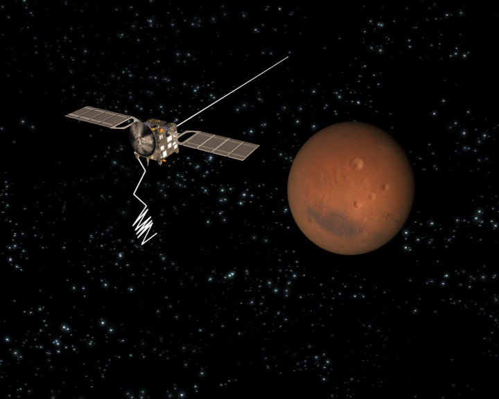
Fig. 1: The European Space Agency’s Mars Advanced Radar for Subsurface and Ionosphere Sounding (MARSIS) was the first spacecraft built with self-deployable composite radar antenna booms. When it entered Martian orbit, one of the multi-hinged booms failed to fully deploy, underscoring the importance of detailed design analysis and testing of the hinge areas. European Space Agency

Fig 2: Boom hinges in the two areas where the boom is folded were designed by thinning or eliminating the laminate. Researchers copied a general design for composite tape-spring hinges found in the literature, pictured here, where L equals slot length, SW equals slot width and D equals circle diameter. Researchers tested three hinge designs in their analysis by varying L and SW. Source: Source: California Institute of Technology
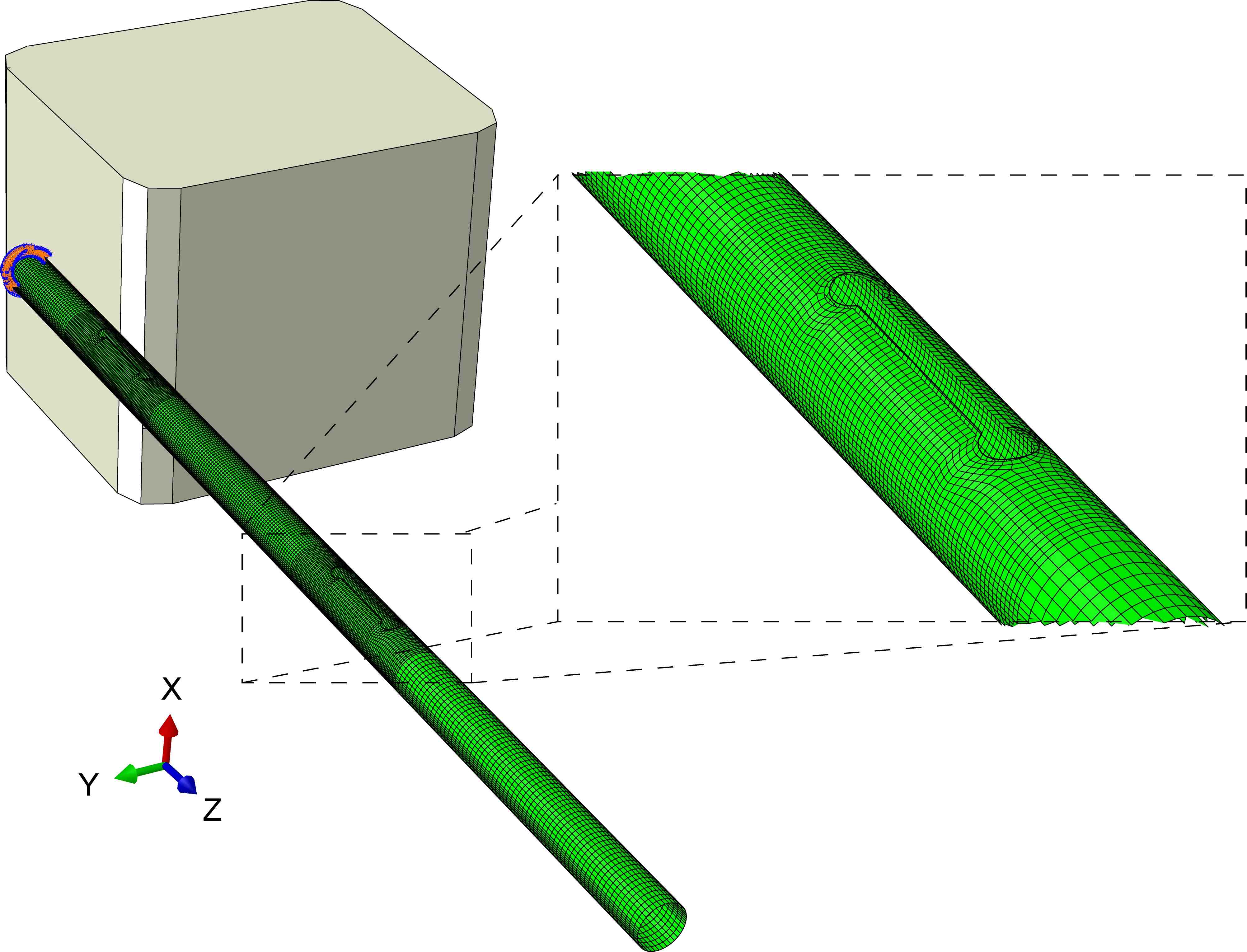
Fig. 3: The final FE model of the boom was a thin-walled tube made of a two-ply laminate that combines plain-weave carbon fiber and epoxy. Boom folding, release and deployment were simulated around an FE model of a spacecraft (the cubic shape in the background). Finer meshing of the model in the areas of the two hinges ( in blow-up) allowed researchers to capture more detail about the stresses in these critical areas. Source: California Institute of Technology
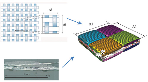
Step 1: Several years of Caltech research into deployable satellite boom construction began, using Abaqus FEA. Each design was meshed with micromechanical modeling techniques, which account not only for ply properties, but define the geometries of the ply’s woven fabric component and matrix. Source: Caltech
Step 2: The next step was to establish the failure criterion. Meshing and simulation of the model with a one-ply laminate revealed that a single ply did not create enough residual energy for full deployment in any of the hinge designs. Researchers repeated the micromodeling phase for a two-ply laminate. Source: Caltech
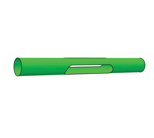
Step 3: Two hinges were created in the model by thinning or eliminating material in the areas where the boom would be folded around a hypothetically shaped spacecraft (see box-like diagram in Fig 3). Source: Caltech
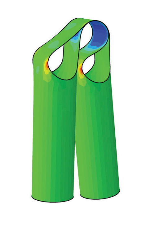
Step 4: The remaining material on each side of the void is pliable enough to be pinched (folded) but (ideally) resilient enough to produce the energy required to deploy the boom as the hinge unfolds. Source: Caltech

Step 5: The final hinge design. Source: Caltech
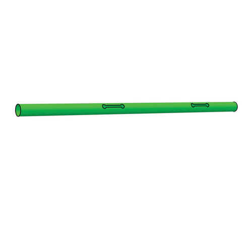
Step 6: The hinge designs, incorporated into the boom design. Source: Caltech


Since the dawn of space exploration, engineers have been challenged to find ways to efficiently package instrumentation into the close confines of a spacecraft lodged in a rocket capsule for the trip into orbit or interplanetary space. Booms are frequently used to deploy solar sails, antennae and other instruments after a spacecraft has reached orbit or landed on a planet. Spring-loaded, self-deploying metal booms have been used since the 1960s. Research on lighter composite versions began in the 1990s. The central challenge was how to quantify and predict composite material behaviors, such as nonlinear deformation, buckling and dynamic snapping, especially with respect to the design of boom hinges. To meet the challenge, software developers have, in the past two decades, created finite element analysis (FEA) programs that not only facilitate calculations and predictions with regard to anticipated component behavior, but also digitally perform a good deal of the design validation that once required costly physical testing.
A recent case in point is a self-deploying composite satellite boom designed, built and validated by researchers at the California Institute of Technology (Caltech, Pasadena, Calif.). The boom incorporates thin-walled, carbon-fiber composite structural segments joined by tape-spring hinges. Designed to activate deployable structures, a tape-spring hinge is an articulating structure that features a resilient but pliable hinge region that can be folded. On each side, there are rigid regions that resist bending, thereby enabling a small fold radius.


On the Caltech boom, two such hinges allow technicians to fold the boom around the perimeter of a satellite. In a deployable structure, the smaller the hinge radius, the greater the packaging efficiency. With that in mind, Caltech researchers pursued the optimum hinge design and radius with the help of a novel analysis technique, based on laminate micromodeling theory and with the help of the Abaqus Unified FEA suite from SIMULIA, a geometric modeling, meshing and simulation software program developed by Dassault Systèmes (Vélizy-Villacoublay, France).
Big payloads in small spaces
“The chief concern with composite hinges,” says Kyle Indermuehle, aerospace lead, SIMULIA, “is that you’re creasing and folding a material that is pretty brittle. You really need to understand the stresses in those areas to design a hinge that will work properly.”
The sensitivity of composite hinge design to uncalculated or unanticipated stresses was brought home with the launch of the European Space Agency’s Mars Advanced Radar for Subsurface and Ionosphere Sounding (MARSIS), which was the first spacecraft built with self-deployable composite booms (Fig. 1). The multihinged, glass fiber-reinforced booms were designed and built by Astro Aerospace, a subsidiary of Northrop Grumman (Redondo Beach, Calif.). After the craft reached Mars orbit in May 2005, one of its two 20m/65.6-ft long composite radar booms failed to lock in place after it was deployed. The problem was caused by thermal effects arising from the boom’s orientation — partly in shade, partly in sunlight. Fortunately, the glitch was fixed a few days later when engineers rotated the craft to receive full sunlight, thus producing sufficient energy to reduce material stiffness in the hinges and cause the boom to self-latch.
One of Caltech’s lead researchers, Chinthaka Mallikarachchi, contends that Caltech’s simulation technique is an improvement over simulation models previously used for composite boom design because it is able to more accurately capture the dynamic loads and stresses that act on the entire structure. “Earlier simulations were done with idealized mass and spring models and based mainly on component testing,” he says, rather than a more thorough “dynamic simulation of the entire structure.”
The Abaqus Unified FEA suite also allows engineers to mimic conditions in space, such as zero gravity, and to analyze the performance of a design under those conditions. This is especially significant because computer simulations can help boom engineers avoid costly physical experiments conducted on aircraft that fly parabolic flight patterns to create near weightlessness for just 30 seconds at a time.
The objective of the Caltech study was to design and validate a structure for a 1m/3.28-ft long boom that could be safely folded around a spacecraft and, after release of constraints on the folded boom, self-deploy without undershoot (a slow, damped deployment that may impede the boom from self-latching) or overshoot (excessive stored energy that can cause the boom to fold back in the opposite direction after it is deployed). The technique used to design and validate the boom comprised five basic steps:
- The geometry and other material properties of fibers and resins that form the laminate were obtained from literature or experiments.
- Micromechanical modeling was used to establish baseline stiffness properties (elastic modulus, Poisson’s ratio) of a periodic unit cell of the laminate.
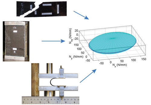
- The laminate’s material failure criterion was established from experiments.
- The material properties of the shell elements of the boom model were defined by meshing the model, using Abaqus/Explicit, and then evaluating the boom and hinge elements of the design by simulating boom deployment and running failure analyses.
- The design was validated by constructing and testing a composite boom made of the laminate materials.
Material selection and modeling
Caltech researchers decided to build the composite boom from a laminate consisting of plain-weave Toray T300-1k fibers (Toray Carbon Fibers America, Flower Mound, Texas) and Hexply 913 epoxy resin (Hexcel, Stamford, Conn.). Mallikarachchi says the main factors that influenced the choice of material for the laminate were cost and the need for a lightweight boom. Further, Toray T300-1k has a low areal density, and both it and Hexply 913 are readily available. The final laminate construction and the wall thickness and diameter of the boom were determined after dynamic FEA modeling of boom deployment and failure analysis (steps 4 and 5, listed above).
Mallikarachchi points out that micromechanical modeling was required because of the ultrathin nature of the laminate plies (about 0.11 mm/0.004 inch) used to construct the boom. The technique differs from classical laminate theory because the latter assumes each laminate ply is a simple plate with certain properties. “Neither classical theory nor FEA modeling can accurately predict the stiffness properties in a composite this thin,” he contends, explaining that micromechanical modeling, by contrast, takes into account the geometric details of woven composites, such as fiber crimp and fiber spacing. “Micromechanical modeling can help you understand the stresses at the fiber and matrix levels, not just the laminate level,” he says. The greater detail available in micromechanical modeling involves a multistep process that is more time consuming and costly and, therefore, not widely used in typical industrial FEA modeling projects. But it is a growing area of research and interest, and SIMULIA’s Indermuehle believes new software or simulation techniques could make it an industry standard in most FE modeling projects within five years.
Most industrial designers use ASTM coupon test results to establish the material properties of a single layer in a laminate of interest. Then they build up the laminate stacking sequence, apply the sequence to the part model, mesh the model (create the nodes that will be solved by FEA equations) and run the FEA simulation. But Abaqus is equipped with a special composites module to assist in the buildup of ply sequences in the laminate.
In the micromechanical modeling phase, Caltech researchers first used Abaqus/Standard (the part of the software package used for solving static analysis and linear dynamic problems) to construct an FE model of a periodic unit cell in a single-ply carbon fiber composite laminate constructed of the specified plain-weave fabric and epoxy. Then they ran six analysis cases by applying six different loads, one at a time, and recorded the reaction forces at the boundary of the model. Mallikarachchi used the results to calculate, via virtual work theory, the ADB stiffness matrix measured in terms of elastic modulus and Poisson’s ratio. An ADB matrix — where A represents in-plane stiffness, D represents bending stiffness and B represents interactions among in-plane loads and bending — is a standard method of defining the stiffness of a composite plate.
The homogenized material stiffness properties obtained from micromodeling were specified in the FE model of the boom (step 4) using the shell general section of Abaqus/Explicit, which is the software module used to simulate the material properties of the model under dynamic and/or nonlinear loads and stresses. The shell general section allows designers to define layups and material properties in a composite matrix. The main criterion that affected the choice of laminate construction and overall boom design was hinge performance. If the laminate is constructed with too many plies, there is a tendency for the brittle composite to crack when the boom is folded. Too few layers in the hinge would not possess sufficient energy to deploy the boom. Because their goal was the lightest possible functional boom, Caltech researchers ran simulations on a boom model with laminates made of one and two plies of plain-weave carbon fiber fabric and three different hinge designs. The orientation of the fabric in the two-ply laminate was symmetrical.
Meshing and simulation of the model with a one-ply laminate revealed that a single ply did not create enough residual energy for full deployment in any of the hinge designs. Researchers repeated the micromodeling phase for a two-ply laminate because extrapolating stiffness properties from a single-ply ADB matrix is not accurate for woven composites. Then the homogenized stiffness properties of a two-ply laminate were applied to the build of an FE boom model consisting of a 1m/3.28-ft long tube with a wall thickness of 0.22 mm/0.008 inch and a diameter of 38 mm/1.49 inches.
Two hinges were created in the model by thinning or eliminating material in the areas where the boom would be folded around a hypothetically shaped spacecraft (see the box-like diagram in Fig. 3, at right) with cross-sectional dimensions of 400 mm by 360 mm (15.75 inches by 14.17 inches). The centers of the two hinges were located at distances of 200 mm and 600 mm (7.87 inches and 23.62 inches) from the root end of the boom. Caltech researchers used results from a previous study that considered a generic tape-spring hinge geometry to settle on three possible hinge designs (referred to by insiders as slots) with three parameters: slot length (L), slot width (SW) and circle diameter (D); see Fig. 2. Only slot width and slot length were varied in the analysis. The use of these previously tested general hinge designs saved researchers considerable time and expense because they did not have to start from scratch and analyze the folding and deployment behavior of many booms with different hinge designs. A finer FE mesh was created in the hinge regions to better capture the stress and load details of the complex deformation that occurs (Fig. 3).
Simulating the boom deployment first required pinching the hinges, so the boom could be folded around the spacecraft, and then releasing all constraints so the boom could dynamically deploy and self-latch. To permit the simulation, the complete model of the boom consisted of 17,644 FE nodes. The spacecraft, by contrast, was modeled simply, with 112 reduced-integration, eight-node brick elements (that is, elements with predefined geometries that expedite meshing of standard or recurring shapes). The bricks were defined to form a single rigid body connected to a reference node. Prior to FEA simulation, five failure tests were run on two-ply laminate test coupons to establish material strengths and failure criteria. The final postprocessing step was the application of the failure criterion to the stress results obtained from the FE simulations and subsequent evaluation of the stresses at each laminate node (with special focus on the hinge areas) to ensure they did not exceed the damage threshold levels.
Mallikarachchi reports that the restart feature in Abaqus/Explicit was especially helpful in enhancing the efficiency of simulations. Testing and analyzing this particular model involved simulating a zero-gravity environment as well as wrapping, holding and releasing the boom. Each of the three steps required a separate analysis. The Abaqus/Explicit restart feature was used to retain the deformation and stress states from the prior analysis as the starting condition for the next stage of analysis.
Realizing the simulation
During the FEA simulations, the first boom design overshot the fully deployed configuration and was rejected. When failure analysis and the hinge angle were optimized against the time response, with full deployment occurring in about 0.3 second, a third design performed better than the second design.
At this point, Mallikarachchi’s team built a boom to the third design’s specifications and physically tested its performance while filming the results from two camera angles. Side-by-side motion comparisons of the FEA Abaqus simulation and actual boom deployment confirmed that the physical boom duplicated the performance of the simulated boom; it deployed in 0.3 second, successfully latched, and then oscillated around the deployment configuration.
Mallikarachchi says the study showed that the hinge transition region between the straight and curved parts of the slot experiences the most stress and that special attention is required in this area during fabrication. He says the simulation developed by the Caltech team can be used to design deployable booms with multiple hinges, alternate laminates and/or optimized boom geometry to meet any customer’s specific mission requirements.
Notably, a number of future missions will incorporate composite self-deployable booms, including the Defense Advanced Research Projects Agency’s (DARPA) Innovative Space-Based Radar Antenna Technology program, which will enable GMTI (ground moving target indicator) radar, particularly from higher (up to 6,200 mile/10,000 km) orbits.
The more than 2,000 communications and research satellites that are currently in space play an indispensible role in the function of an increasingly global society. Space, however, exacts a heavy toll: Intense radiation, temperature fluctuations, static electricity buildup and meteorite and space-junk collisions degrade, and sometimes end, satellite performance. Satellite replacement, therefore, should continue to provide steady business for aerospace contractors and national space agencies. As these contractors and agencies look for ways to extend the longevity of satellite components, reduce payload weight and, especially, limit the time and cost of testing, this Caltech case study suggests that ever more sophisticated simulation software will enable them to make inroads on all these fronts and produce more easily packaged satellites at significantly lower cost.


.jpg;maxWidth=300;quality=90;format=webp)


Related Content

Novel dry tape for liquid molded composites
MTorres seeks to enable next-gen aircraft and open new markets for composites with low-cost, high-permeability tapes and versatile, high-speed production lines.
Read More
The lessons behind OceanGate
Carbon fiber composites faced much criticism in the wake of the OceanGate submersible accident. CW’s publisher Jeff Sloan explains that it’s not that simple.
Read More
Cycling forward with bike frame materials and processes
Fine-tuning of conventional materials and processes characterizes today’s CFRP bicycle frame manufacturing, whether in the large factories of Asia or at reshored facilities in North America and Europe. Thermoplastic resins and automated processes are on the horizon, though likely years away from high-volume production levels.
Read More
Price, performance, protection: EV battery enclosures, Part 1
Composite technologies are growing in use as suppliers continue efforts to meet more demanding requirements for EV battery enclosures.
Read MoreRead Next

Composites end markets: Energy (2024)
Composites are used widely in oil/gas, wind and other renewable energy applications. Despite market challenges, growth potential and innovation for composites continue.
Read More
CW’s 2024 Top Shops survey offers new approach to benchmarking
Respondents that complete the survey by April 30, 2024, have the chance to be recognized as an honoree.
Read More
From the CW Archives: The tale of the thermoplastic cryotank
In 2006, guest columnist Bob Hartunian related the story of his efforts two decades prior, while at McDonnell Douglas, to develop a thermoplastic composite crytank for hydrogen storage. He learned a lot of lessons.
Read More