
Sailing the sea with composite wings
Autonomous sailing vessel patrols with patented WingSail technology.

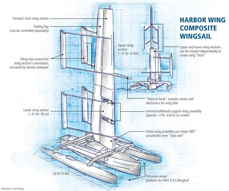
Harbor Wing Composite WingSail. Illustration: Karl Reque
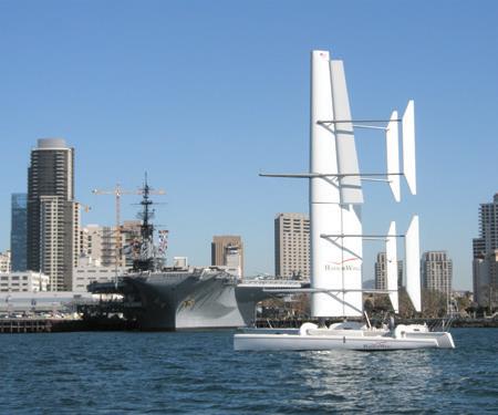
The HWT X-2 undergoes sea trials in California (bottom). Note the “balance beaks” protruding in front of the wing sail, which hold the electronic equipment that controls the two wing tails, to the rear of the wing. Source: Harbor Wing

This photo shows the rigid WingSail during fabrication. Note the trailing flap (slightly yellow in the photo), the substantial carbon tubes that support the wing tails, and a bulkhead visible at left, inside the airfoil-shaped wing structure. Source: Harbor Wing

This computer-generated rendering shows the entire X-3 trimaran, which will include T-shaped hydrofoils designed to increase craft stability and speed. Source: Harbor Wing


Engineering Challenge:
Develop a means to propel an unmanned surface vessel for reliable and maintenance-free performance.
Design Solution:
An all-composite rigid wing system, free to rotate 360° around a fixed mast and controlled by a computer.


Sailors have been furling and unfurling, and generally wrestling with voluminous sails for millennia. But naval architects and engineers for almost a century have pondered the concept of a simple wing. The most dramatic example is the huge rigid carbon fiber structure installed on the 2010 America’s Cup winner, BMW Oracle’s USA, which at 223 ft/69m tall is more than twice the length of a Boeing 747 aircraft wing (see "BMW ORACLE ...." and "USA wins ...." listed under "Editor's Picks").
Although sailboats powered by wings have proponents and naysayers, Mark Ott, the cofounder, director, executive VP and manager of Harbor Wing Technologies (Seattle, Wash.), contends that wings are clearly superior to conventional — what he calls soft — sails. “In terms of power, a wing is much more efficient than a soft sail,” he says. “Per square foot, a wing delivers up to 1.7 times the power of soft sails with much lower drag and actuation force.” (Read about composite soft sails, molded by North 3Di (Minden, Nev.), in “Custom-engineered composite performance yacht sails” under Editor's Picks" at right.)
That’s because a soft sail requires a fairly substantial breeze to get the vessel moving, and its movement in response to changing wind loads dissipates power and causes aeroelastic collapse and drag, slowing forward momentum. Further, when Harbor Wing paired its patented WingSail with its new HWT X-3 catamaran, the “goal was an unmanned sea vessel,” Ott notes. Without a crew, “a soft sail setup wouldn’t have worked.” An autonomous (self-controlled rather than remotely controlled) unmanned sea vessel (AUSV), the HWT X-3 design has already earned accolades from the U.S. Navy and the U.S. Department of Defense (DoD), and the X-1 proof-of-concept catamaran and X-2 preproduction prototype trimaran have undergone intensive testing.
Sailing without sails
As early as the 1920s, German engineer Anton Flettner conceived of vertical metal wings as substitutes for sails. John Walker, a British aeronautical engineer, designed the Walker Wingsail and launched the Wingsail-outfitted trimaran Planesail in 1966. He still supplies wing sails to commercial and recreational sailors (Shadotec plc, Salisbury, Wiltshire, U.K.). During the late 1990s, Harbor Wing’s Ott, together with engineers David Hubbard and Dr. Sam Bradfield, designed Volantis, a radical multihulled open-ocean racer that, although never built, provided elements that formed the DNA of the HWT X-3.
Building on past wing concepts, Harbor Wing has, with its WingSail, advanced the science significantly, says Ken Childress, the company’s executive VP of business development. “Our unstayed wing is free to rotate 360° around the mast, in any direction. It’s a real departure from former designs, since the wing force is effectively uncoupled from the vessel below.” The wing team included Ott, Hubbard — who helped design BMW Oracle’s USA wing — and naval architect Duncan MacLane (MacLane Marine Design, Shelton, Conn.).
Ott explains that a monumental wing like the one used in the America’s Cup wasn’t appropriate for the X-3: “A lot of the America’s Cup racing is theatrics. We had to have something more controllable, without stays, that would not overpower the platform [vessel], yet still be lightweight and robust.” Harbor Wing started with a fixed mast or “stub axle,” designed as a thick-walled, tapered carbon fiber/epoxy cylinder mounted at the vessel’s center of gravity, using finite element analysis (FEA) software. A significant percentage of unidirectional axial fibers would give very high longitudinal stiffness in order to handle and transmit thrust from the wing assembly to the vessel, without deforming under constant bending loads. The stub axle would support the wing’s rigid all-composite, 800-ft2/74m2 airfoil, which is made with internal “bulkheads” similar to ribs in an aircraft wing (see drawing) spaced approximately every 2 ft/0.62m and bonded to the wingskins. Selected bulkheads would be fitted with bearings to enable rotation. The entire wing assembly would slide down over the stub axle. The wing would have a forward “main” section with a leading edge, as well as a trailing flap, which could be moved separately for lift “shaping,” as is done with an aircraft wing, explains Childress. To enhance control, the team divided the wing assembly itself into independent upper and lower sections. This wing-on-wing configuration allows the vessel to take advantage of wind gradients (differences in wind speeds), depending on height above the water. The split design effectively would give a rigid sail the ability to “twist” like a soft sail. In strong winds, the upper wing could be reefed (turned into the wind, or depowered) while the lower half still could provide propulsion.
To control the wing assembly, Ott’s group devised and patented wing tails that extend behind the upper and lower wings. Connected to the stub axle at four bulkhead locations, the wing tails would be equipped with worm-gear-driven linear actuation motors controlled by the company’s WingSail Control software (pat. pend.). “The twin tails are big lever arms,” explains Ott. “We developed our proprietary sail-by-wire software to send signals to the wing tails to change the wing sail’s orientation.” The stub axle would be fitted with optical strain gauges to detect bending moments caused by the wind loads as well as thrust and overturning moments. That data would be interpreted, and appropriate commands would be sent to the wing tails five times per second to instantly adjust the wing surfaces so the mast and wings couldn’t be overstressed. The software, says Ott, “achieved a very high degree of control and can do anything with the boat, including sail backwards.” The tails’ motors and battery would be housed in the “balance beaks,” which extend forward of the wing.
Autonomous with composites
The design was realized using a variety of composite materials selected to combat the harsh marine environment and minimize weight. High-modulus HR40 carbon fiber material, supplied by Grafil Inc. (Sacramento, Calif.), was selected for the stub axle to provide maximum tensile stiffness. The mast height and wing size is scalable to any application, says Ott, but for the X-2, the designers determined the optimum mast height as 62 ft/19m, with a base 18 inches/0.46m in diameter, tapering to 7 inches/180 mm at top. Hall Spars & Rigging (Bristol, R.I.) fabricated and autoclaved the stub axle on a male mandrel, supplied by Custom Composite Technologies Inc. (Bath, Maine). The hollow axle accommodates wiring for in-mast sensors, such as cameras or radar.
The wing sail and tail parts are each fabricated by Composites Universal Group (Scappoose, Ore.) in one-piece, on male mandrels, using E-glass wet out with epoxy resin supplied by Newport Adhesives and Composites Inc. (Irvine, Calif.) and are cored with either Corecell styrene acrylonitrile (SAN) foam (supplied by Gurit UK, Isle of Wight, U.K.) or aluminum honeycomb, says Ott. Aramid fiber was incorporated into the wing leading edges for added impact resistance, and some carbon fiber was used in locations that required extra stiffness. The bulkheads are flat carbon fiber/epoxy plate stock, which is CNC-machined to shape. The wing tail arms are simple carbon/epoxy tubes. Secondary bonding (e.g., bulkheads to wingskins) was accomplished using epoxy adhesive from Pro-Set Inc. (Bay City, Mich.). RexNord (Milwaukee, Wis.) supplied the large, low-friction composite bearings that enable wing rotation on the stub axle.
The X-2 is a 50-ft/15.4m long Contour 50 trimaran. It has a 41-ft/12.5m beam width, a narrow center hull and two outrigger hulls. Built by Contour Yachts (Erin, Ontario, Canada), it was engineered by yacht designers Morrelli and Melvin (Huntington Beach, Calif.) to carry the stub axle and WingSail. The vessel was modified by Knight and Carver Boatyard (National City, Calif.). “The HWT X-2 wouldn’t have been possible without composites,” notes Ott.
Custom hulls for the X-3 (full-scale production) version have been designed but not yet built, says Childress. The hull payload capacity for computer systems, radios and more, is ~1,500 lb/~682 kg. Childress reports that the HWT X-1, during tests in Hawaii, has successfully maintained course and station instructions and reached a top speed of >25 knots/29 mph. “Our wing configuration has less drag than a traditional bare mast and rigging when turned directly upwind, or feathered, so it’s very safe. The computer automatically turns the wing into the wind during mooring so that the wing can’t gain an angle of attack. And it’s most definitely not fragile. It’s built to hold up without ... maintenance for long durations.”
If it is adopted by defense agencies, the X-3 could stay at sea for more than three months, particularly if it is outfitted with renewable power sources or energy-scavenging systems.
Beyond the DoD, Harbor Wing has heard from ferry operators, including Wind + Wing Technologies (Napa, Calif.), looking for wing-sail-powered ferries in San Francisco Bay and Washington State. And commercial shippers (huge consumers of fossil fuels) and recreational boaters are keenly interested. For the latter, the WingSail on a manned vessel could be controlled easily, with a joystick, a Morse-type throttle or via computer touch screen.


.jpg;maxWidth=300;quality=90;format=webp)


Related Content

Resins, additives, adhesives and 3D printing solutions
CAMX 2023: Arkema’s broad portfolio of products for composites fabricators aim to enhance performance, durability and sustainability.
Read More
Park Aerospace launches aerospace, MRO structural film adhesive
Aeroadhere FAE-350-1 is a curing epoxy formulation designed for composite, metal, honeycomb and hybrid applications.
Read More
Scott Bader ATC begins Crestabond MMA structural adhesive production
Scott Bader’s Drummondville, Canada, facility has begun manufacturing and supplying composites-applicable adhesives to its North American customers.
Read More
Pontacol thermoplastic adhesive films are well-suited for composite preforms
Copolyester- and copolyamide-based adhesive films eliminate the need for sewing threads or binders when stacking laminates while improving the final part’s mechanical properties.
Read MoreRead Next

Custom-engineered composite performance yacht sails
North Sails introduces 3Di materials and process for structural composite sails.
Read More
Composites end markets: Energy (2024)
Composites are used widely in oil/gas, wind and other renewable energy applications. Despite market challenges, growth potential and innovation for composites continue.
Read More
From the CW Archives: The tale of the thermoplastic cryotank
In 2006, guest columnist Bob Hartunian related the story of his efforts two decades prior, while at McDonnell Douglas, to develop a thermoplastic composite crytank for hydrogen storage. He learned a lot of lessons.
Read More