
Rapid Fiber Preforming On A Large Scale
A proven alternative to open molding of big parts.


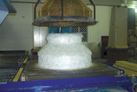
Source: NCCStep 5: The outer screen is robotically removed (large top shown).
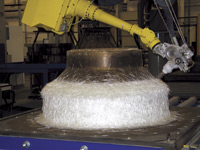
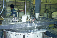
Source: NCCStep 2: The RFP chopper head on the LSP's 6-axis robot sprays dry binder and chopped fiber over the preform screen.
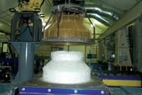
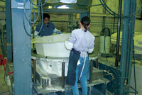
Source: NCCStep 3: After sprayup, a 4-axis robot places a second preform screen-tool over the first screen to compress the fiber/binder to part thickness.
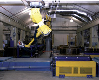
Source: NCCNCC's computer-controlled Large Scale Preformer has a processing envelope big enough to produce preforms as large as 40 ft by 14 ft by 8 ft high.
Source: NCCStep 7: The preform is injected with vinyl ester resin and cured in the mold for 15 to 20 minutes.
Source: NCCStep 8: As soon as the mold begins to cool, two operators remove the cured part and prepare it for shipment.
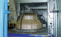
Source: NCCStep 4: The preform enters a heated oven, where the binder is melted and consolidated with the fiber at 149°C/300°F.
The National Composite Center (NCC, Kettering, Ohio), a nonprofit composite process development corporation funded by private industry and government awards, has been a preforming proponent since 1997, when initial National Institute of Standards and Technology (NIST) and U.S. Department of Energy (DoE) research dollars were awarded to NCC to produce composite pickup truck boxes, using Owens Corning's Programmable Powder Preform Process, dubbed P4. (see CT April 2002, p. 32) Following that project, NCC adapted P4 and demonstrated the ability to produce complex shapes with carbon fibers at significant cost reductions for the U.S. Air Force. NCC subsequently adapted the technology for commercial applications, developing the process the NCC today calls Rapid Fiber Preforming (RFP), designed for composites with chopped, long fiber reinforcement.
Since then, NCC has continued its preforming research incorporating RFP into three preform production cells designed to generate preforms with accurate part wall thickness, complete with integral rib stiffeners, openings, cores and other elements of the final part configuration. The three cells, geared respectively for small, medium and large performs, have the combined capacity to produce a range of near net-shape preforms sized from as small as 2 ft by 2 ft by 2.5-ft high (0.6m by 0.6m by 0.8m) to as large as 40 ft by 14 ft by 8-ft high (12.2m by 4.2m by 2.4m).


"Our mission is to move composites manufacturers out of hand layup and open molding into more environmentally-acceptable closed-molding alternatives," says NCC president Lou Luedtke, who points out that a reliable source of preforms is a necessity for volume-production in closed-mold processes, such as resin transfer molding (RTM), vacuum-assisted RTM (VARTM) and vacuum-assisted resin infusion molding (VARIM).
LARGE-PART PREFORMER
Large preforms are facilitated by NCC's most recent addition, the Large Scale Preformer (LSP). The LSP's computerized sprayup process requires no human contact from the time the tooling enters the preform manufacturing cell until it is ready to be demolded: spray-up, compression, cure of the binder, cooling and demold operations are all accomplished robotically, according to instructions preprogrammed into the system's software. Alan Fatz, program manager for NCC, describes LSP as "a smart system that tells us where every part is in the process at all times."
In 2005, NCC made 10,000 preforms, 7,000 of which were large pieces made with the LSP. The LSP system was made possible, in part, by the donation of a $4 million (USD) gantry-style tape placement machine from Boeing Phantom Works (St. Louis, Mo.) in 2002, says Fatz. The machine's gantry frame became a very stable platform for a 6-axis robot with 68-kg/150-lb payload capacity, made by Fanuc Robotics America Inc. (Rochester Hills, Mich.).
The LSP's inaugural application — and the largest preform produced thus far — was for fuel containment vessels RTM'd by Retterbush Fiberglass Corp. (Piqua, Ohio) for OPW Fueling Components (Cincinnati, Ohio). OPW installs them beneath gasoline pumps in gas stations to prevent contamination of soil if there is a leak in the pump-to-tank plumbing. Before Retterbush began manufacturing them by RTM, the vessels were made by hand layup of flat goods. "The time savings with the preforms is incredible" says Mike Palsgrove, plant manager for Retterbush. Equally important is the consistency of the NCC preforms, he adds. "We get the same quality every time: consistent shape, consistent thickness — it's a much better way to mold the parts."
Molded in two parts (top and bottom) and bonded/bolted together during installation at the job site, the vessels provide a subsurface housing for connections between the pump and underground fuel tanks (see drawing, p. 28). They were an ideal candidate for LSP because their function required no aesthetic finish — NCC's preforming experience, thus far has been with non-gel coat applications, but Fatz says the company is investigating what steps might be necessary to prevent print-through of the preform pattern.
The vessel bottoms are 12-faceted sumps 19.7 inches high by 51.8 inches in diameter (500 mm by 1,316 mm) at the widest point, which is the trough, or flange, around the upper perimeter. The tops are made in two sizes: Large tops are 30 inches high by 51.6 inches in diameter (762 mm by 1,310 mm). Small tops are 18 inches high by 51.6 inches in diameter (457 mm by 1,310 mm) Depending on the application, either a small or large top is attached to the sump bottom.
COMPOSITE DESIGN
In the design stage of a preform project, NCC first analyzes the mechanical and physical property requirements of the product by finite element analysis (FEA), failure mode analysis and other analysis programs to determine which materials, reinforcement types and manufacturing processes would be best suited for the application. For this purpose, NCC has purchased powerful composite software programs that in-house design engineers have integrated into a custom analysis package, according to Fatz. Software includes ABAQUS (ABAQUS Corp., Providence, R.I.), Genesis with Design Studio (VR&D, Colorado Springs, Colo.), SolidWorks (SolidWorks Corp., Concord, Mass.), COSMOS (Structural Research & Analysis Corp., Monica, Calif.) and Cadpress (The Madison Group, Madison, Wis.).
Strength requirements dictate the fiber architecture and establish whether continuous reinforcement is necessary or — as was the case with the Retterbush fuel containment vessel — more cost-effective chopped fibers will do the job, using RFP preforms. For the Retterbush project, the best material combination for both top and bottom parts was determined to be 2-inch/50.8 mm chopped E-glass with an epoxy binder to build a wall thickness of 0.15-inch/3.8-mm, ±0.030-inch/0.762-mm.
To date, most of NCC's commercial preforms have been E-glass chopped to similar length, but the RFP equipment can be programmed to vary, on the fly, both fiber output and fiber length — the latter from less than 0.5 inch to greater than 3 inches (1.27 mm to 76.2 mm). While carbon and S-glass also have been chopped for aerospace and defense applications, Kevlar has resisted all chopping efforts. "We are still trying to find a way to do that," says Fatz.
Unlike wet sprayup methods commonly used in other preforming processes, RFP uses powdered (dry) binders, which avoid volatile emissions. NCC also is investigating "string" binders, essentially thermoplastic fibers that are commingled with the glass, a product supplied by PPG Industries (Pittsburgh, Pa.). Binders may be thermoset or thermoplastic, and all NCC binders are compatible with most polyester, vinyl ester and epoxy matrix resins. Thermosets are typically required for high-temperature molding processes (above 225°F/107°C). Less- expensive thermoplastics can be used for lower-temperature processes. The binder accounts for 3 to 7 percent of an NCC preform's weight.
Design analysis indicated that the parts would need a 30 percent glass loading. It was later determined that about 10 percent additional glass loading was needed in the floor of the bottom part to minimize the possibility that puncture by a rock or other debris, Palsgrove notes. Retterbush had previously strengthened the floor with hand-layed multiaxial fabrics. While oriented unidirectional or multiaxial fabrics also can be hand layed into the RFP preforms prior to molding, this step was unnecessary for the Retterbush vessel bottom, because the LSP can direct chopped fibers into discrete areas of a part. Although RFP technology cannot orient fibers to obtain specific fiber architecture, part thickness and/or glass content can be increased. In this case, only glass content was increased, not the wall thickness, so no change in the part molds or molding process was necessary.
PREP FOR PRODUCTION
Preform tooling for each vessel component consists of two perforated metal screens that duplicate the bottom sump and large/small top shapes. One screen forms the component's inner face and is the tool over which the preform is sprayed. The outer screen conforms to the shape of the part exterior, and is used to compress the preform to net part thickness during the curing and cooling stages. The screen-tool sets are built either by NCC or by outside vendors to NCC specifications. For this project, NCC constructed three of the four tool sets (inner and outer screen-tools). The fourth was manufactured with the assistance of Thornton Industries (Albion, Pa.). Mounted on pallets that are guided by a roller conveyor system, the screen-tools index automatically through the four stations during the 10-minute production cycle.
For the Retterbush parts, the sprayup screen was treated with a water-based mold release from one of several suppliers, typically once or twice each shift — approximately every five or six cycles.
In the initial setup, the robots must be individually programmed, which typically requires, on average, two shifts, with another shift to run and approve pilot samples, says Fatz. "After three shifts, you're usually ready to start producing parts." Then recipes must be input into drop-down windows in the software and saved for recall. Input requires about 15 minutes per part. While programming requires trained technicians, recipe input may be done by production operators.
When screens are ready, attention moves to the sprayup station: Typically, two fiberglass rovings are pulled through a feedtube in the LSP's chopper head from reinforcement packages mounted on nearby weight scales, which the LSP's computer uses to monitor the weight loss of the fiber supply, the key variable in controlling part fiber volume. The process is ready to begin.
ROBOTIC VERSATILITY
When a screen enters the spray station, a dynamic seal creates a plenum, and allows air pressure variance within the space. A high-output fan draws a vacuum through the back side of the screen. As sprayup begins, binder powder is fed from a supply tank (mounted above the robot) through an auger screw that dispenses it at a specified rate into a supply tube, where it is air-driven into the gun and sprayed onto the screen tool with the fiber. The LSP chopper sprays the tool in a prescribed pattern, working about 12 inches to 18 inches (305 mm to 457 mm) from the tool surface. Binder and fiber are immediately captured by the vacuum and held in place on the screen tool.
Control of airflow is especially critical when working on convex (male) molds or vertical surfaces and deep draws on concave (female) molds, such as those for the Retterbush vessels. "In addition to the flexibility of the robot, we have other options for accurate fiber distribution," Fatz says. "We have two ways of controlling static air pressure. We can change the fan speed and we can use baffling to increase air flow speed to create a specific application pattern on the screen." Static pressure requirements are custom-designed for each part to trap the fibers on the screen without pulling them through. "This ability to adjust the vacuum is particularly important," Fatz explains. "As we build up material toward a condition called 'blinding the screen,' the vacuum pressure must be increased to ensure fiber retention." Binder "blow through" is effectively minimized after the initial layer of glass is applied, and binder content can be varied in process. Therefore, the system can be programmed to effectively prevent binder loss as successive glass layers are applied.
At this stage, integral rib stiffeners or other features can be incorporated by placing an "interim" tool over the built-up preform. Sprayup then continues as the interim tool blocks off certain areas of the perform and isolates others for localized buildup. (Reinforcement fabrics or cores, when needed, may be layed up at any point in the sprayup process.)
After sprayup is complete, the outer screen-tool, which conforms to the exterior shape of the part — including any integral stiffeners or other features — is robotically retrieved from a holding area and placed over the preform by a second, 4-axis Fanuc robot with 1,000-lb (453.6 kg) payload capacity. The vacuum is shut down and the preform is shuttled into a closed, heated oven, where the binder is melted at about 300°F (149°C) and consolidated with the fiber. Though hot air circulating in the oven may reach up to 400°F (204°C), infrared sensors signal the computer to put the oven in a holding, or low-temperature, mode when the screen reaches 300°F (149°C). Once the "set point," is reached (in 10 minutes or less), the "smart" system opens the heater doors and the part exits into an enclosed cooling zone, where circulating forced air brings the preform down to safe-handling temperature (<120°F/49°C).
After the preform leaves the cooling zone, the 4-axis robot removes the second screen and returns it to the holding area to await the next cycle. The preform then is manually demolded from the sprayup screen-tool, and stacked 7 to 10 high on a pallet for shipment to Retterbush. After demolding, the tool automatically rotates to the first station for the next production cycle.
READY TO RTM
The finished preform needs no trimming or deflashing and is well-compacted and robust enough to require no special handling to avoid damage during molding operations. "Many preforms are a loose blanketing sprayed up on one-sided screens, which then have to be pressed into the final part shape," explains Fatz. "Our preforms are very close to part thickness and shape." To RTM the vessels, therefore, an operator at Retterbush can simply hand-lift a preform off the pallet stack and load it into the lower, female half of the open RTM mold.
The upper mold is closed into the lower mold hydraulically, at about 1,800 psi (12.4 MPa) pressure, and the preform is injected with resin at ~40 psi, (0.276 MPa) using a Gusmer injection system from Gusmer | Decker (Lakewood, N.J.). The resin is Hexion 1470561 vinyl ester supplied by Hexion Specialty Chemicals (Carpentersville, Ill.). Palsgrove reports that Retterbush currently has two RTM presses running 12 to 15 complete vessels per day. Loctite Frekote 44, a semipermanent, solvent-based mold release from Henkel Corp. (Rocky Hill, Conn.), reportedly gives Retterbush 250 to 300 parts between applications.
The parts are cured for 15 to 20 minutes in the mold, which is pre-heated to about 100°F (38°C) by circulating hot water between the walls of the double-wall mold. "We allow the part to go to peak exotherm and then start cooling in the mold, and we demold it as soon as it starts to cool," Palsgrove says.
Parts are separated from the mold faces by compressed air, demolded by two operators (due to their increased weight), deflashed and labeled. Bottoms are vacuum tested for leakage, and tops are drilled with six holes for six bolts. The parts are then shipped to OPW for secondary fabrication and installation.
RELIABLE PREFORMS
While NCC has the ability to make the preforms for molders and also can mold the final product, NCC's goal is to license it to molders and provide ongoing technical support. "We assist in scale-up and we assist in finding government money from SBIRs and other sources," Luedtke explains. In a novel arrangement, Composites One is the distributor of composite materials to NCC and its customers and licensees, and is also the exclusive distributor of molded preforms made by NCC's RFP process. "If we transfer our preforming technology to a molder, Composites One will serve as its distributor for any extra product," Luedtke explains. Fatz explains that Composites One can ship preforms at costs significantly lower than those of commercial shippers, by making use of space available in partially loaded trucks. This enables the molder to step up its production beyond existing contracts, and sell preforms to other molders, which, in turn, helps expedite the cost savings that are achieved at higher volumes. At part volumes totaling 1,000 or more, Luedtke estimates NCC's RFP process saves up to 30 percent in manufacturing costs, compared to hand layup and open molding.
Luedtke notes that in addition to the preforms for RTM, VARTM and other infusion-based closed molding processes, NCC is considering hybrid preforms for compression molding processes, where they would be impregnated with SMC or BMC to provide additional reinforcement and strength in a finished part.
The potential for replacing hand layup with reliable, robust preforms, even for large parts, holds significant promise for open molders, and for the composites industry as a whole, as it strives to compete with traditional metal materials and still meet the challenge posed by ever-increasing environmental regulations.


.jpg;maxWidth=300;quality=90;format=webp)


Related Content

Improving carbon fiber SMC simulation for aerospace parts
Simutence and Engenuity demonstrate a virtual process chain enabling evaluation of process-induced fiber orientations for improved structural simulation and failure load prediction of a composite wing rib.
Read MoreSMCCreate 2023 invites attendees, presentation speakers
The SMC/BMC-focused event will take place from Nov. 7-8 in Prague, targeting experienced designers and those that may be new to applying SMC/BMC materials.
Read More
Composite resins price change report
CW’s running summary of resin price change announcements from major material suppliers that serve the composites manufacturing industry.
Read More
Materials & Processes: Fabrication methods
There are numerous methods for fabricating composite components. Selection of a method for a particular part, therefore, will depend on the materials, the part design and end-use or application. Here's a guide to selection.
Read MoreRead Next

Composites end markets: Energy (2024)
Composites are used widely in oil/gas, wind and other renewable energy applications. Despite market challenges, growth potential and innovation for composites continue.
Read More
CW’s 2024 Top Shops survey offers new approach to benchmarking
Respondents that complete the survey by April 30, 2024, have the chance to be recognized as an honoree.
Read More
From the CW Archives: The tale of the thermoplastic cryotank
In 2006, guest columnist Bob Hartunian related the story of his efforts two decades prior, while at McDonnell Douglas, to develop a thermoplastic composite crytank for hydrogen storage. He learned a lot of lessons.
Read More