
Pultruding cost out of aerospace parts
Design-for-manufacturing effort proves to be cost-effective for carbon/epoxy airfoil on expendable UAV.

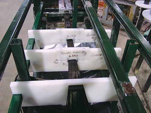
Fiber guides: Continuously wet out fiber tows are shaped by a series of guide “cards” just before they enter the pultrusion die. Source: KaZaK Composites
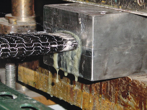
Entering the die: The outer off-axis fabric layer, which has been shaped around the mandrel and encloses the tows that form the stiffening ribs, is shown as it enters the die. Source: KaZaK Composites
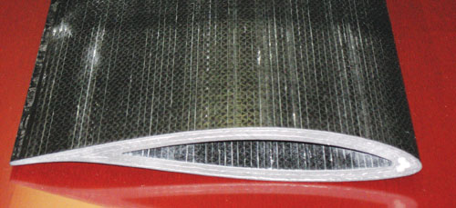
Pultruded wing: An example of a pultruded hollow wing without internal ribs. Note the extreme alignment of the carbon fibers, a characteristic of pultruded parts. Source: KaZaK Composites
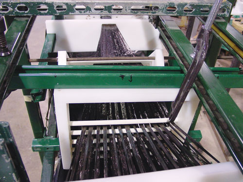
Fiber wetout: During the wing pultusion process, collimated dry carbon fiber tows enter the wet epoxy resin bath. Surce: KaZaK Composites
KaZaK Composites Pultruded Wing Design Illustration: Karl Reque


Design Results
- Production of single-use, consumable wings for weapons or UAVs is automated, using the pultrusion process.
- Wing design meets flight performance requirements despite sacrificing some aerodynamic details for more efficient, lower-cost manufacture.
- Pultrusion permits integral stiffening ribs to be incorporated into the wing in a single-step process.
The unmanned aerial vehicle (UAV) has become a potent weapon in the U.S. Armed Forces arsenal. These remotely operated “drones” have made headlines by providing military commanders a means of gathering intelligence and delivering ordnance with precision. A growing trend in the UAV market involves relatively small, single-use UAVs that, equipped with cameras and wireless communication gear and spared the concern of pilot fatigue, can loiter for days on surveillance missions and might be deployed in “swarms” to guide and protect soldiers and convoys or act as defensive decoys when launched from a manned aircraft (see “Learn More,” at right).
Designing an expendable UAV from
composites presents an obvious challenge: How to produce a viable
aircraft capable of carrying mission-specific communicators, sensors or
other equipment at a cost low enough to justify a single flight?


One
option is to use low-cost, automated methods for key parts. KaZaK
Composites Inc. (Woburn, Mass.) has demonstrated the feasibility of
pultrusion with innovative designs and manufacturing strategies for UAV
wings, as well as other high-value parts for space missions and
military applications.
To make expendable aircraft feasible, production and material costs have to be kept to a minimum, says KaZaK’s president Jerry Fanucci. Although pultrusion often fits the bill, “we don’t think of ourselves as a pultrusion company,” he maintains, pointing out, “we design composite parts, and if pultrusion is the right solution, then we use it.” According to Fanucci, KaZaK is a full-service design and production company, capable of developing not only UAV wings but also entire unmanned aircraft, including selection of the airfoil shape and definition of vehicle aerodynamics. “It ultimately depends on the performance requirements, but if pultrusion is the answer, then it works for aerospace as well as for industrial applications.”
Designing for low-cost manufacture
As most
composites engineers know, pultrusion is a continuous molding process.
A creel system pays out reinforcing materials, in the form of
unidirectional roving, woven cloth, multiaxials, braided preforms
and/or nonwoven mats that are continuously drawn through a moving
production line by a system of alternating pullers. Reinforcements, in
some cases, pass through a preheating furnace, which heats and dries
them to improve resin wetout. Materials then are positioned or shaped
as required. For example, woven cloth could be folded over or placed
off-axis as it passes through one or more forming devices. The
materials then are passed through an open resin bath with a doctoring
system that afterward removes excess resin. Alternatively, it enters an
enclosed injection die, where resin is forced under pressure directly
onto the reinforcements. The wet-out materials then immediately pass
into a heated steel pultrusion die, where they are compressed to the
final part shape and cured. When the cured part exits the die, it can
be cut to the desired length as it moves, with a traveling cut-off saw.
Pultrusion
produces parts with constant cross-sections, most commonly simple
tubes, rods, beams or flat plates — but any complexly-shaped
two-dimensional profile is possible, and even tapering profiles can be
considered, notes Fanucci: “A common misconception about pultrusion is
that it can only produce parts with unidirectional reinforcement but,
in fact, almost any multi-angle laminate can be achieved by using
pre-plied broadgoods or inline filament winding.” As a continuous
automated process, pultrusion can produce very high-quality parts with
tight tolerances of virtually unlimited length, he adds.
“Because
the reinforcements are always under tension, you can achieve very high
fiber alignment and straightness,” he says, contending that such
precision is often unattainable “with a hand layed part cured in the
autoclave, where the autoclave pressure can cause some distortion.”
Costs
are significantly lower for pultrusion than for any other composite
production methods due to several factors. Dry reinforcements and
liquid resin together cost less than prepregs, and labor costs are very
low because the process is automated. Other cost savings can be gained
in the tooling. Pultrusion dies are short, normally only 2 to 4 ft (0.6
to 1.2m) in length, so they can be produced fairly economically. “No
matter how long your part or the number of copies,” says Fanucci, “the
tool cost is the same, and relatively low compared to a layup tool.”
Evolving concepts for manufacturable wings
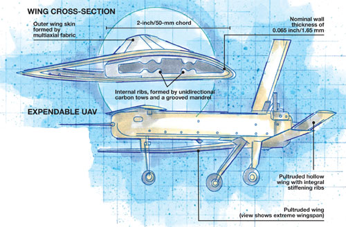
With an eye to these advantages, the company pursued and received two Small Business Innovation Research (SBIR) grants to design wings for weapons. The grant funded programs that evolved into a design for a telescoping wing for a swarm-type, long-loiter UAV, as well as the design for the company’s own disposable gliding UAV, developed for the U.S. Navy as an expendable, GPS-controlled sonobuoy delivery system.To keep part costs as low as possible, some design compromises had to be made, notes Fanucci. One of the wing projects, for example, involved an SBIR customer that provided the external aerodynamic wing shape, with an approximate 2-inch/50-mm chord. Previously developed as part of the client’s overall vehicle design, and necessary to achieve the UAV system’s performance, the wing shape was non-negotiable. But the means by which KaZaK might provide the stiffness required to combat air loads and produce sufficient lift in the wing was not prescribed and included a range of solid, hollow and internally ribbed options.
Based on
the given wing shape, KaZaK employed a finite element model based on
air loads and stiffness requirements. The goal was to determine the
composite laminate structure that could best handle the loads by
manipulating the fiber architecture while staying inside the required
outer aerodynamic shape. The company primarily used ANSYS software from
ANSYS Inc. (Canonsburg, Pa.) and SolidWorks from Dassault Systèmes
Solidworks Corp. (Woodland Hills, Calif.) to create the multi-ply wing
laminate. But Fanucci says the company also has access to other FEA and
CAD programs, when required by an application. The FEA analyses
prompted selection of a hollow wing design with lengthwise interior
stiffening ribs and a wall thickness of approximately 0.065 inch/1.65
mm.
During the selection process, an important consideration
was “design for manufacturability,” where the company looked at
available reinforcement material forms and considered how difficult it
might be to pultrude prospective designs: “Anyone looking at pultrusion
is interested in cost minimization,” says Fanucci. “So we often iterate
several designs with the customer to arrive at a compromise that gives
the needed performance, provides the best cost/weight value and is also
easiest to manufacture.” The lengthwise stiffening ribs, for example,
could be pultruded integrally with the wing, eliminating extra
manufacturing steps. However, one client design feature, a
several-degree root-to-tip twist to improve stall performance, was
eliminated. Although KaZaK previously had produced twisted, pultruded
wings, Fanucci points out that the cost is higher and, in this case,
the marginal improvement in flight did not justify the additional
expense: “For a consumable UAV, cost drives the design more than
aerodynamic performance.”
When the wing shape and laminate
design model were complete, the next step was to design the root end
termination, where the pultruded wing attaches to the vehicle body.
Depending on loads and other details, this feature can be a pivot or
other deployment mechanism, in metal or composite, and is usually
bonded into the hollow wing as an insert at the root end. Fanucci
explains that for some contracts, internal telescoping mechanisms are
needed inside the wing. These enable the wing to deploy, spanwise, as
the root section pivots. With all of the various design elements in
place, KaZaK turned to designing the pultrusion process.
Pultruding skins and ribs in one step
To make the hollow wing with interior stiffening ribs, the selected reinforcements included a stitched unidirectional carbon fabric manufactured by Fabric Development Inc. (Quakertown, Pa.), quadraxial carbon fabric supplied by Vectorply Corp. (Phenix City, Ala.) and continuous carbon tows from Grafil Inc. (Sacramento, Calif). The selected resin was aerospace-grade Epon 862 epoxy, supplied by Hexion Specialty Chemicals (Houston, Texas). The epoxy formulation is a proprietary “tweaked” version, modified with accelerators to ensure rapid cure at the pultrusion line speed (~12 inches/300 mm per minute).The
pultrusion line had to be tweaked as well. Multiple unidirectional tows
were fed in conventional manner from the creel and through the first of
two resin-injection dies. To ensure that the resin’s viscosity would be
low enough to thoroughly wet out the fiber, it was preheated prior to
injection. As the impregnated reinforcements exited the die, they were
pulled through a progression of “cards,” or machined plastic blocks
(see center photo, below), that bundled the tows together and gradually
manipulated and positioned the bundles around a stationary
airfoil-shaped mandrel, which was machined with grooves at the rib
positions. Simultaneously, layers of wet out quadraxial fabric were
pulled through formers that folded the materials around the outside of
the mandrel, enclosing and securing the tow bundles in place just
before they entered the second injection die, which is required to
ensure complete wetout of the laminate stack. Immediately afterward,
the layup was pulled through the heated die and cured. Parts were cut
to length, and the metallic root end terminations were bonded.
The
resulting wing has an intricate interior cross-section and a
fiber/volume fraction in excess of 60 percent — approximately the same
as the typical autoclave-cured prepreg part. Subsequent mechanical
testing, including cantilever and four-point bending tests, showed the
wing withstands loads predicted by the model, consistent with its
laminate design, says KaZaK.
Providing low cost and high quality
Often
overlooked by manufacturers of aerospace parts, pultrusion — as
demonstrated here — is clearly a viable candidate for certain
applications, where the very low cost and automated process can deliver
high-performance parts. “The best-performing composite structures are
not very practical if they can’t be economically manufactured,”
observes Fanucci, noting that KaZaK has performed numerous trade
studies that show how pultrusion can reduce the cost of carbon fiber
structures in a variety of markets by 50 percent or more, compared to
other fabrication techniques, yet deliver comparable fiber volume and
performance.


.jpg;maxWidth=300;quality=90;format=webp)
Related Content

Materials & Processes: Fabrication methods
There are numerous methods for fabricating composite components. Selection of a method for a particular part, therefore, will depend on the materials, the part design and end-use or application. Here's a guide to selection.
Read More
RUAG rebrands as Beyond Gravity, boosts CFRP satellite dispenser capacity
NEW smart factory in Linköping will double production and use sensors, data analytics for real-time quality control — CW talks with Holger Wentscher, Beyond Gravity’s head of launcher programs.
Read More
Novel composite technology replaces welded joints in tubular structures
The Tree Composites TC-joint replaces traditional welding in jacket foundations for offshore wind turbine generator applications, advancing the world’s quest for fast, sustainable energy deployment.
Read More
Plant tour: Albany Engineered Composites, Rochester, N.H., U.S.
Efficient, high-quality, well-controlled composites manufacturing at volume is the mantra for this 3D weaving specialist.
Read MoreRead Next

Blended Wing UAV
Unique unmanned craft's robust composite design a plus for rough duty.
Read More
Composites enable micro air vehicle
Real-time sensing capability makes slow-flight VTOL MAV a "man replacement."
Read More
Composites end markets: Energy (2024)
Composites are used widely in oil/gas, wind and other renewable energy applications. Despite market challenges, growth potential and innovation for composites continue.
Read More