
Preforming goes industrial: Part 2
Automated preforming isn’t only for 2D and 2.5D parts. Innovators are taking successful aim at building 3D preforms at production speeds.

Tailored fiber preplacement: 3D preform enabler
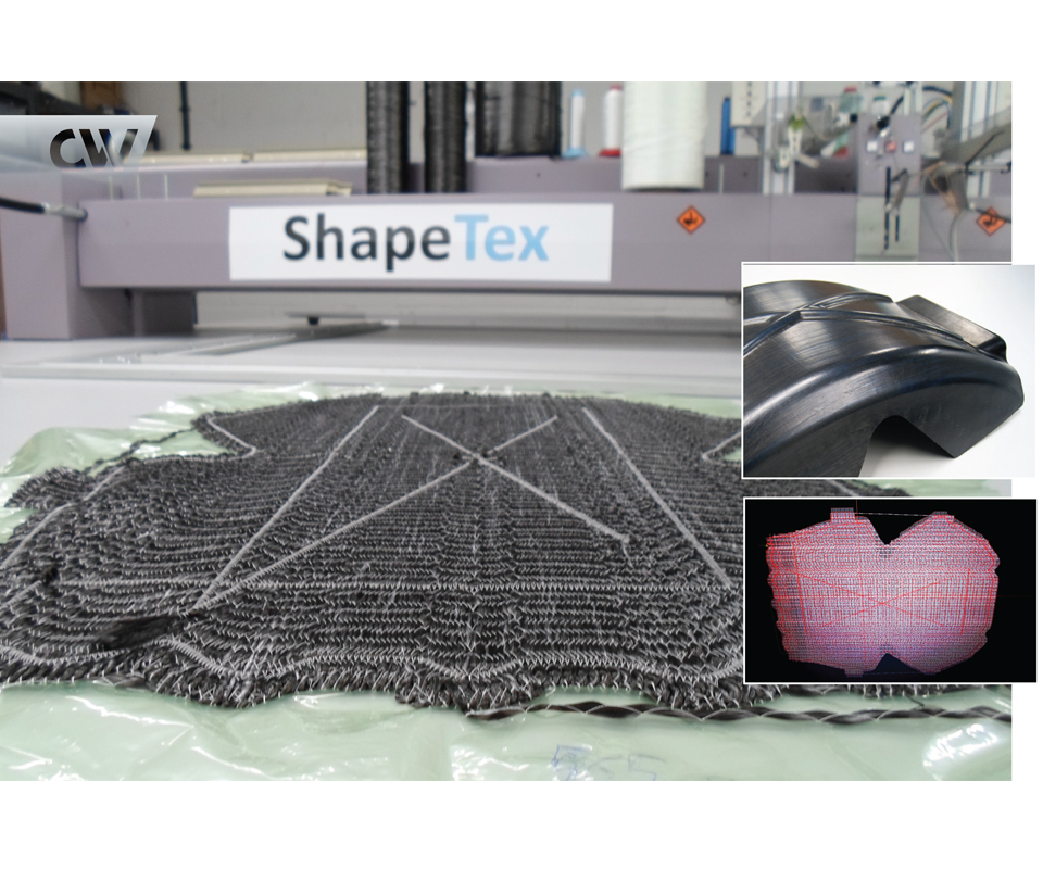
Shape Machining Ltd.’s (Witney, UK) composite parts production gets automated using digital design, commingled fibers (e.g., carbon and polyamide) and the modified embroidery technology that is the foundation of tailored fiber placement (TFP). What result are ShapeTex preforms that are ready for pressing into thermoplastic parts or for use as inserts for overmolding. Source: ShapeTex
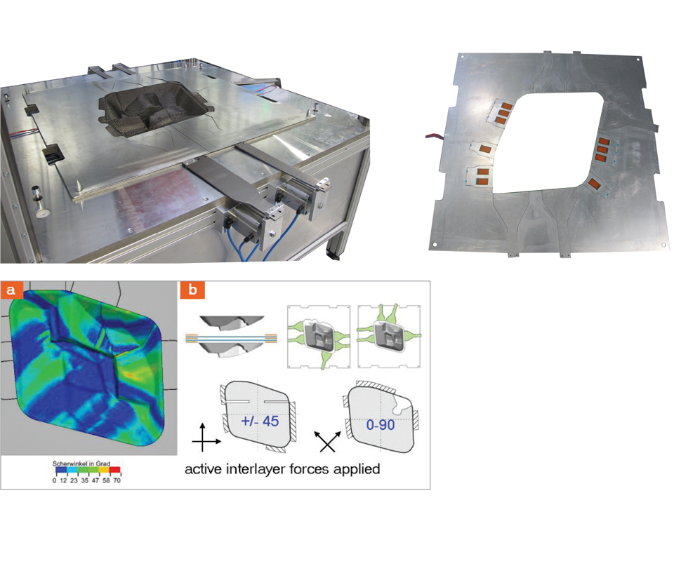
Fig. 1: Active wrinkle/defect prevention
Active interlayers are metal sheets — placed between plies at the outer molded edge during preforming — which are stimulated with piezo actuators to reduce friction (above).
Active interlayers can reduce or eliminate wrinkles and other defects in complex geometry preforms when combined with tailored clamping of discrete plies (shown above left).
Based on a draping simulation and subsequent forming limit diagram, active interlayers were developed to achieve wrinkle-free preforms for a Mercedes-Benz E-coupe model decklid, applying diagonal force to 0°-90° NCF layers and 0°-90° force to ±45° NCF layers (a and b, bottom left). CIKONI (Stuttgart, Germany) developed it into a low-cost automated preforming system for mid-range part volumes with a 3-minute cycle time including automated cutting and handling. Source: CIKONI GmbH
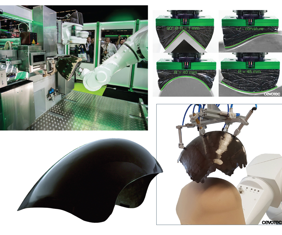
Fig. 2: Robotic patch placement for fast 3D parts
Cevotec’s (Taufkirchen/Munich, Germany) SAMBA automated preforming cell uses two choreographed robots to position tailored-length unidirectional patches onto complex 3D tooling, ready to be molded into 3D parts with no further consolidation or forming steps required. Source: Cevotec
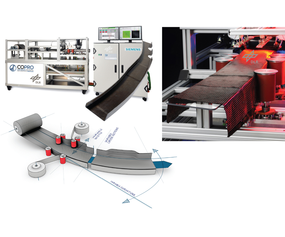
Fig. 3: Continuous-process complex parts
In COPRO Technology’s (Braunschweig, Germany) continuous preforming process, opposing rollers on linear tracks change the width, taper and cross-section of bindered dry fabrics or prepregs into C-, T-, Z- and closed-profile preforms, complete with joggles, oriented ply build-ups and drop-offs and local reinforcement patches. Source: COPRO Technology GmbH
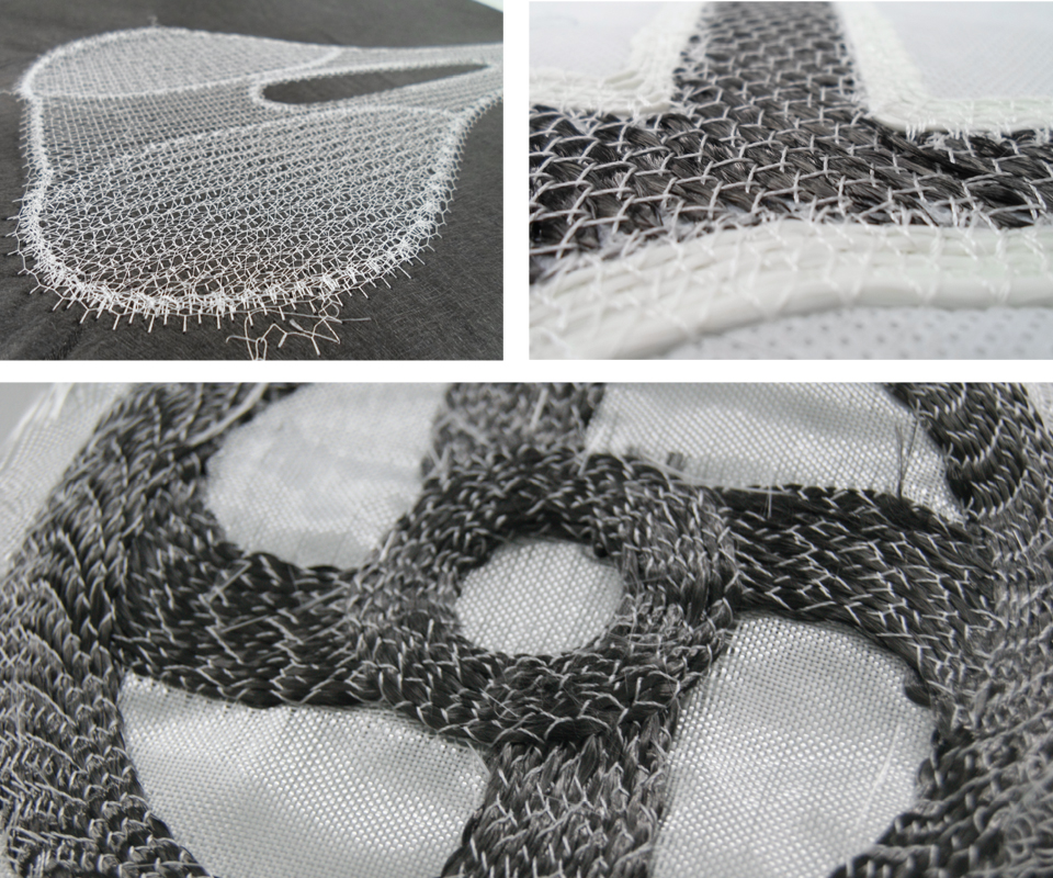
Fig. 4: TFP scrims: wash-or melt-away convenience
Orienting fiber in shapes other than just a straight line, ShapeTex preforms are stiched to a substrate (e.g., thin fiber scrim, recycled fiber viel, fabric) some of which can be washed away prior to resin transfer molding or melted during hot pressing of commingled laminates. (Source: ShapeTex).


In CW’s July 2017 feature, “Preforming goes industrial, Part 1”, CW looked at a variety of processes, each based on automated tape laying (ATL) and/or automated fiber placement (AFP), that have been amended to perform within the 1- and 2-minute cycle-time window required for high-volume (e.g., >100,000 parts/yr) automotive applications. However, much of the automation in preforming to date has employed cutting, placing and forming of woven and/or noncrimp fabrics (NCF). This second installment discusses techniques — both digital and mechanical — that can be applied to speed the forming of such stacked fabrics into three-dimensional (3D) shapes without wrinkles or fiber distortions, but also spotlights methods, including roll-forming derived from metal tube and beam fabrication and the latest developments in tailored fiber placement (TFP) technology, that impart 3D shape as an inherent part of the preforming process.
Savings through simulation
Composites consulting company CIKONI (Stuttgart, Germany) has applied its expertise in composites design, finite element (FE) analysis and advanced simulation to offer solutions for automated preforming. “Typically, preforming is thought of as a passive process, where you apply pressure and produce a preform,” says CIKONI co-founder Dr. Farbod Nezami. “But with our approach,” he contends, “you can act upon the preform to dramatically improve its quality and also the weight reduction and performance of the finished part.”


One part of CIKONI’s approach is called active interlayers. These are metal sheets placed between the plies at a preform’s outer edge, which are then stimulated with piezo actuators to reduce friction. When combined with tailored clamping of discrete plies, the active interlayers can reduce or eliminate wrinkles and other defects in preforms with complex geometries. The active interlayers are not part of the finished preform, but instead are removed and reused.
“This approach is not appropriate for every situation,” Nezami advises. “You need to have a certain degree of design complexity and a need for high quality.” Although the interlayers are not expensive — just laser-cut sheet metal and very low-cost actuators — using them is a multi-stage process that relies on computer aided engineering (CAE). Nezami explains, “We use FE-based draping simulation to produce a forming limit diagram which helps us to identify and assess areas of risk for wrinkles and/or fiber waviness.” CIKONI then tailors the arrangement and forces imposed by the active interlayers to remediate only these areas.
A recent case history is CIKONI’s work with Mercedes-Benz (Sindelfingen, Germany) on an E-coupe model decklid. The woven carbon fabric preform, surrounded by active interlayers, can be seen in Fig. 1 (above). CIKONI performed a draping simulation that identified the need for dart cut-outs in both the 0°/90° and ±45° NCF layers (Figs. 1a & b). The subsequent forming limit diagram was then used to design the active interlayers, which were clamped in different areas (green funnels and hashed boxes in Fig. 1b).
“These clamping areas were tested via iterative simulations and then optimized experimentally,” explains Nezami. “We were able to remove the initial fiber waviness completely and reduced the size of wrinkles from 11 mm to 3 mm, so that they remained only outside of the main load-carrying and visible areas.” Although Nezami argues that active interlayers are only one possible solution, for Mercedes-Benz, CIKONI developed it into a low-cost automated preforming system for mid-range part volumes with a 3-minute cycle time, including automated cutting and handling.
3D preforming vs. 2D and 2.5D
Thorsten Groene, managing director of the preforming technology company Cevotec GmbH (Taufkirchen/Munich, Germany), contends that most automated preforming processes output a 2D preform that still requires a forming step to achieve a 3D composite part. “It is difficult to achieve different thicknesses within the preform with typical blank-building technologies,” he argues. Cevotec’s SAMBA process, he counters, produces 3D fiber preforms with different fiber orientations and thicknesses directly from the CAD file in one step, with no additional forming operations necessary nor a need for draping tools.
Launched as an “industrial preforming system” at JEC World 2017 (Mar 14-16, Paris, France), SAMBA is based on fiber patch placement (FPP) technology, with an integrated software suite called ARTIST STUDIO. SAMBA uses a pick-and-place robot and a second tool-manipulation robot to precisely place tailored-length fiber patches at calculated positions along load paths, using a form-adaptive patch gripper to position the patches onto complex 3D molds (Fig. 2). Precise cutting of the patches is achieved via laser, and two industrial camera systems continuously inspect and document the quality and placement of each patch. Groene says the system produces more than one patch per second, using 30% less material than fabric preforms, yet achieves up to 150% greater stiffness and strength. “This is a new option for series production that was not available before,” he adds.
Software also is a key part of Cevotec’s approach. “When you think about developing preforms for complex composite parts, the software is key to hardware and process efficiency,” Groene explains. “Larger parts, especially, are composed of more patches than you can manually handle. Our ARTIST STUDIO software uses powerful algorithms with ‘fiber intelligence’ to create high-performance laminates,” he continues. “The entire part geometry can be loaded into our ARTIST STUDIO software. Based on just a few, intuitive user parameters, the software automatically creates an optimized patch laminate and a set of machine data for SAMBA. You don’t need to develop anything else. We’ve removed quite a few steps from the process to maximize efficiency.”
Another FPP distinguisher, already demonstrated by Cevotec in series production (see Fiber patch preforms help tailor kiteboard performance), is the ability to efficiently produce curvilinear paths in the preform. “You cannot do this with tape laying,” Groene insists.
“We are producing 2D layups because this is production in automotive today,” maintains Dr. Matthias Meyer at Broetje Automation (Rastede, Germany). “We can have a touch of 3D in our layers, but truly 3D layup is too cost-intensive for the auto industry.”
Compositence GmbH (Leonberg, Germany) also claims an ability to achieve preform geometry between 2D and 3D — i.e., 2.5D — a concept already widespread in CNC machining and computer graphics. “This is the maximum we can reach, depending on the geometry of the preform, because the diameter of the compaction roller and size of the placement head prevents reaching every angle for fiber placement,” Thomas Dobiasch, head of sales, explains. However, Compositence’ patented edge fixation for accelerated 2D placement provides a kind of “work-around” for achieving 3D layups. “It allows us to pull fibers into areas that we cannot reach due to the size of the AFP head,” says Dobiasch. “Our software calculates the total fiber length needed to conform into this area, and this is what is placed onto the 2D or 2.5D preform. When you subsequently complete the 3D forming of the blank, the fibers will move and conform into this area.” He cautions that this movement also depends upon the type of material placed to form the preform.
For thermoplastic preforms, Dobiasch contends that robotic placement can achieve true 3D shapes, “but consolidation requires a second step and you must work in 2.5D to hit a 1-minute takt time. We have not seen 100% consolidation of thermoplastic tows during layup of true 3D shapes.”
FILL Gesellschaft mbH (Gurten, Austria) is working to further develop its AFP system for 2.5D and 3D preforms, aiming to reduce forming steps required before molding. This system reportedly will be able to process a range of materials, including prepregs, thermoplastic tapes or dry fiber tapes.
Continuous 3D preform processing line
Another process that claims true 3D preforms with no further forming steps has been developed by COPRO Technology GmbH (Braunschweig, Germany). A spin-off from the German Aerospace Center (DLR) facility in which it is located, COPRO emerged from research with Airbus and aerocomposites suppliers to automate preforms for aircraft door frames. Its patented continuous process now extends to fuselage frames, wing and empennage stringers as well as nonaerospace parts, such as automotive sills, rails and struts, wind turbine blade spars, and frames for trailers and industrial machines.
The process uses rollers to feed, shape and consolidate layers of reinforcements, eliminating preform tooling while enabling fast production of profiles. C-, T- and Z-profiles and typical closed shapes are enabled, but so are shapes with variable curvature, cross-section, width and thickness. “We use roll-forming like in the metals industry,” says COPRO managing director Henrik Borgwardt, “but we can make more complex shapes.”
“The input reinforcements depend on the profile geometry and structural design,” says co-founder Arne Stahl, “but for stringers and beams, we can use anything on a roll. The rollers sit on linear tracks so they can move from side to side to change the width and taper of the profile.” (Fig. 3). “We can also achieve joggles in this way,” he adds. Joggles are bump-outs or local changes in the profile’s shape enabling it to conform to its mating surface (i.e., stringer to wingskin) throughout thickness changes (e.g., ply buildups and drop-offs).
“For consolidation, the rollers provide compaction and we have used infrared heating to tack the bindered dry fabrics or prepregs,” says Borgwardt. “We’ve also used inductive heating for faster process time and thicker laminates.” COPRO has processed straight profiles with as many as 10 layers at speeds of 400 mm/sec, and curved profiles, with as many as four layers, at a rate of 50 mm/sec for more complex shapes, such as door surround frames, which use as many as three layers of biaxial or triaxial NCF (e.g., ±45° or ±45°/90°).
The COPRO approach handles localized shaping. But can it provide local reinforcements? “We can start and stop input bands like an ATL head,” says Stahl. “We do the same for stringer flanges, feeding in 0° unis from extra side spools, or start extra layers before a joggle and stop after a joggle. We can also combine with a pick-and-place robot for other types of patches.”
TFP evolves
CW reported on the use of tailored fiber placement (TFP) for preforming in 2013 (see Tailored Fiber Placement: Besting metal in volume production). “The first automotive composites application for TFP was 15 years ago in the engine brackets of the Bugatti Veyron,” says Tailored Innovations (Highland, MI, US) founder Tommy Fristedt. He notes that more than 100 TFP machines, adapted from industrial embroidery equipment, have been installed for preforming composites in Europe and Asia. Tajima GmbH/Filacon Systems (Winterlingen, Germany) has a license to sell the machines.
“TFP allows orienting the fiber in shapes other than just a straight line,” says Fristedt, “for example, as reinforcements for holes and hard points for attachments.” It can use glass, carbon, aramid and polymer fibers in a range of tow sizes. “We have processed heavy fiber, up to 610K, from Oak Ridge National Laboratory [Oak Ridge, TN, US],” he adds, “but, of course, this has to be combined with knowledge of how to achieve resin impregnation to achieve a good preform design.”
Patrick Schiebel, a research engineer at Faserinstitut Bremen eV (FIBRE, Bremen, Germany), has worked with TFP for 12 years and is now developing preforms that use a single thermoplastic as reinforcement and stitch fiber. “We have produced load-optimized preforms, which are quickly thermoformed into parts,” he explains. “The Airbus A350 window frames, made using TFP, are processed in four hours, using RTM, but require only half an hour with thermoplastics.” These preforms also may be overmolded to integrate bosses, ribs and attachment points into the final part. “We’ve made preforms using this technique with polyetheretherketone (PEEK) and polyaryletherketone (PAEK from Victrex [Cleveleys, UK],” says Schiebel.
He points out that the preconsolidated preform must be heated again to get a good interface with the overmolded plastic. Using the lower melt temperature PAEK as preform and overmolding with PEEK works well. “You can also use PA6 and PA66,” adds Schiebel, who also reports making preforms with curved paths as small as 10 mm in diameter.
Shape Machining Ltd. (Witney, UK) also is using TFP to produce thermoplastic composite preforms (Fig. 4). “Our technology came from working with Stuttgart University,” says managing director Peter McCool. His company is producing ShapeTex preforms using SYNERGEX commingled fibers from Coats (Uxbridge, UK). “Our most popular materials are carbon fiber/polyamide for automotive, carbon fiber/PEEK for aerospace and carbon fiber/polypropylene for recreational applications,” says McCool. Because the technology is based on stitching, a substrate is required, but he maintains there are many options available. “We can apply to a thin fiber scrim, recycled fiber veils or anyone’s fabric,” McCool explains. “We can wash it away prior to RTM and also use a variety of backing materials that are compatible with hot pressing of commingled laminates.”
With a background in Formula 1 racing and carbon fiber prepreg, McCool appreciates TFP’s ability to align fibers only and exactly where needed. “There is no fabric to trim or cut,” he says, “so there’s very little waste. With our advanced FEA capability, we can be quite smart in the development of efficient preforms.”
The company is scaling up one automated production line for aerospace and another for automotive. “For the latter, we’re starting a project aimed at 15,000 parts per year,” says McCool, noting that each machine is equipped, standard, with a dozen identical stitching heads, enabling it to produce as many as 12 preforms, simultaneously. “We can also lay down larger tows for higher throughput.” He says Shape has already demonstrated hot pressing capability for high-quality parts and is ramping that to low annual production volumes. “The number of inquiries we’ve had is staggering,” notes McCool. “There is a great deal of interest in the ability to produce optimized composite parts in an industrialized way while minimizing waste.”
For more detailed discussions of these and other preforming processes, standardized drapability testing, preform simulation software and solutions for aerospace and wind energy structures, please see the CW Blog’s Preforming series Automated Preforming — The numbers and landscape.


Related Content

ASCEND program update: Designing next-gen, high-rate auto and aerospace composites
GKN Aerospace, McLaren Automotive and U.K.-based partners share goals and progress aiming at high-rate, Industry 4.0-enabled, sustainable materials and processes.
Read More
Clemson Composites Center: Working with industry to transform composites
Offering liquid and thermoplastic composites molding, LCA-weighted simulation, full testing to validate materials/process data cards, CCC’s digital life cycle approach unites manufacturing, microstructure, part property map and structural analysis.
Read More
Multi-material steel/composite leaf spring targets lightweight, high-volume applications
Rassini International was challenged by Ford Motor Co. to take weight out of the F-150 pickup truck. Rassini responded with a multi-material steel/composite hybrid leaf spring system that can be manufactured at high volumes.
Read More
Protecting EV motors more efficiently
Motors for electric vehicles are expected to benefit from Trelleborg’s thermoplastic composite rotor sleeve design, which advances materials and processes to produce a lightweight, energy-efficient component.
Read MoreRead Next

From the CW Archives: The tale of the thermoplastic cryotank
In 2006, guest columnist Bob Hartunian related the story of his efforts two decades prior, while at McDonnell Douglas, to develop a thermoplastic composite crytank for hydrogen storage. He learned a lot of lessons.
Read More
Composites end markets: Energy (2024)
Composites are used widely in oil/gas, wind and other renewable energy applications. Despite market challenges, growth potential and innovation for composites continue.
Read More
CW’s 2024 Top Shops survey offers new approach to benchmarking
Respondents that complete the survey by April 30, 2024, have the chance to be recognized as an honoree.
Read More