
Plane Enthusiasts Plan LSA-compliant Composite Aircraft
Aspiring owners build and - plan to market - their own tandem seat, twin-boom pusher.


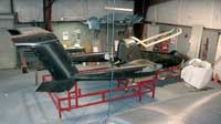
Source: Ion AircraftThe prototype hull and twin-boom tail assembly for the Ion 100/105.
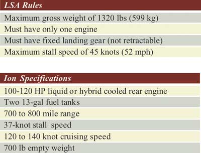
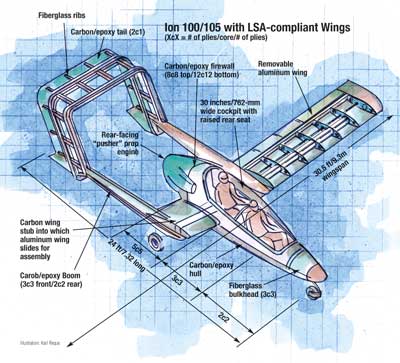
Illustration: Karl Reque
In the 1990s, Steve Schultz, CEO of Ion Aircraft (St. Paul, Minn.), was one of about 145 people who placed orders and laid down deposits for a small plane that never made it off the drawing board. Schultz and fourteen others, mostly disappointed customers like himself, decided that rather than giving up on their dream, they would design and build their own plane. The following year Ion Aircraft was born and, today, has four working employees — Schultz, a machinist, an engine specialist and a welder.
LSA-compliant … and more


From Ion's beginning, the goal has been to build a beautiful airplane with good performance at a reasonable price. The plane would be able to comply with the rules for the U.S. Federal Aviation Admin.'s (FAA) Light-Sport Aircraft (LSA) category, recently created to ease the qualification process both for aspiring pilots and aircraft manufacturers (see HPC May 2003, p. 52, and HPC September 2005, p. 38). Additionally, it was to have tandem seating, with a raised rear seat — giving pilot and passenger an unobstructed, panoramic view — plus a rear-facing powerplant tucked between its twin boom tail, and easily removable wings. The latter permit the plane to be stored in an enclosed trailer, which saves hundreds of dollars on airport storage fees, and enables Ion to offer the plane with interchangeable wings: a longer set that make it LSA-compliant (see chart, p. 70) and/or a shorter set that adds 12 knots to the plane's speed but brings its stall speed above the LSA limit.
Ion's aircraft will ultimately be available in four models: the 100, 105, 110 and 120. The 100 is a kit aircraft that meets LSA rules, while the 105 is an experimental, non-LSA-compliant aircraft that is based on the 100 design but can be customized to suit the owner. A 105 may, for example, have an in-flight adjustable-pitch prop to allow blade angle changes during climbing vs. cruising for increased efficiency, or it may have shorter wings, or retractable landing gear, none of which are allowed under LSA rules. The 110 will be modified for the European market, and the 120 will be a ready-to-fly, factory-finished aircraft. Ion is currently building the first prototype of the 100/105, with flight-testing planned for spring and summer of 2006. The expected empty weight of the plane is a little over 700 lb/317 kg, with a gross weight of 1,320 lb/599 kg, permitting a useful load of 600 lb/272 kg for cargo, fuel and two passengers. With a fuel tank capacity of 26 gal/98 liters, the plane's cruising distance will be 700 to 800 miles (1,129 to 1,290 km).
Ion contracted with design firm AirBoss Aerospace (Reno, Nev.), whose engineers began with the lower fuselage and internal parts, and then proceeded to the upper fuselage, the tail, nose, closeouts and removable wings. Initially, a CAD file of the design, created in SolidWorks (SolidWorks, Concord, Mass.), was input into a proprietary computational fluid dynamics program written by Analytical Methods Inc. (AMI, Redmond, Wash.). The hull shape was analyzed for the proper lift distribution, high and low pressure areas, laminar vs. turbulent airflow, and airflow separation areas. The program checked the geometry for excessive eddies or vortices in the airflow over the plane's surface. Then the model was optimized, for example, by modifying the hull shape to minimize afterbody airflow separation. Too severe an angle on the afterbody will separate the airflow from the rear of the fuselage too quickly, changing the flow from laminar to turbulent, thus creating a low pressure area at the end of the aircraft body, says Schultz. By changing the surface geometry to minimize this condition, Ion will make the plane cruise faster, use less fuel and feel smoother in flight.
Part architecture
Once the outer shape of the plane was determined, internal and structural parts were designed to fit inside. Cosmos finite element analysis (FEA) software from Structural Research and Analysis Corp. (SRAC, Santa Monica, Calif., a SolidWorks subsidiary), features a direct plug-in to SolidWorks, and was used to ensure that composite laminate and part stiffness and strength met Federal Aircraft Regulations (FAR) 23 regulations, which specify factors of safety of 1.5 for metal parts and 2.0 for composite parts. For materials selection, the rule of thumb was that for primarily two-dimensional parts, such as wing panels, it would usually be faster and cheaper to use aluminum, but for more complex, three-dimensional parts, such as the fuselage, it would be better to go with composites for strength and reduced part count. Cost vs. performance trade studies analyzed aluminum vs. composite for the removable wings, fiberglass vs. carbon fiber for the fuselage, and filled injection-molded plastic vs. aluminum for the ribs. Study results led Ion to determine that the wing skins should be bonded aluminum, while the fuselage, booms and tail would be carbon fiber, with internal ribs and cowl of fiberglass. All the Ion's composite parts are sandwich structures. They are made with a 0.25-inch/6.35-mm Nomex core and ±45° skins, some of 7781 and 7725 fiberglass (from various suppliers) prepregged with Jeffco 1300 series resin, supplied by Jeffco Products (San Diego, Calif.) and some from Toray Composites America's (Tacoma, Wash.) AGATE-qualified 12K plain-weave carbon prepreg (T700S/2510), which has a wet Tg of 262°F/128°C and a dry Tg of 293°F/145°C. Woven fabric is used for ease of layup of the contoured parts. The skins are bonded to the core with Newport Adhesives & Composites Inc. (Irvine, Calif.) NB101N film adhesive. Ion and prime fabrication contractor Composites Unlimited (CU, Scappoose, Ore.) chose to make the parts with prepreg in a vacuum bag/oven cure process since that is an aircraft industry standard that has worked well over the years. Since the booms are round and long, Ion initially thought filament winding might be a good process, but determined that the tooling was too expensive. Instead, CU decided to use carbon composite tooling layed up on a high-density foam master.
The carbon fiber fuselage is layed up in two halves, a top and a bottom, joined just below the canopy with a 1-inch/25.4 mm overlap. The fuselage skin thickness increases from two plies between the nose and the pilot seat to five plies toward the rear of the fuselage, while the firewall, between the engine and the rear of the cockpit, varies from 8-ply skins on top to 12-ply skins on the bottom.
Internal flat pieces, such as the front bulkhead, were layed up as flat plates with three layers of 7725 fabric per skin bonded to the core with film adhesive. A 1:1 scale paper template was then plotted out and used to trim the plates. The trimmed plates were then bonded directly to the fuselage using the fiberglass "wet-taping" method. In all bonding operations, CU is using either standard bonding with Hysol 9360 epoxy (Henkel Corp., Bay Point, Calif.) or wet taping. When wet taping, parts are joined together with 2-inch/50.8-mm wide plies of the same laminate as the sandwich skin to be joined. The pieces are wet out using Jeffco 1300 series laminating epoxy, an aircraft industry standard. Peel ply is used to smooth the edge transition and/or it is sanded after cure.
Twin boom tail and detachable wings
Two of the biggest design challenges have been the tail and the removable wings. With a rear-mounted engine, the tail must be attached to the fuselage from above, underneath or around the prop. Ion chose the latter option, a twin boom tail, for looks and structural reasons. An aircraft's tail offsets the weight of the pilot in front, and so must have enough surface area and rigidity to properly control pitch and yaw movements. However, too much surface area creates excessive drag, and too much weight can cause balance problems.
For the removable wings, Schultz and his team developed an attachment system based on one used in German sailplanes 20 years ago. Female wing stubs extend from the fuselage through slots in the booms, which are "wet taped" to the stubs. Each wing assembles by sliding it into the wing stub and pinning it in place with two 6-inch/15.24-cm long 303SS pins — a cam-shaped pin in the cockpit and a 0.75-inch/19.1-mm diameter round pin in the boomline, both going into 4130 steel brackets bolted to the fiberglass wet taped shear web. In addition there are smaller pins for the flaps and ailerons. To attach the 55 lb/25 kg wings to the plane requires only five minutes, although it is strongly recommended that two people do the job to prevent the wind from taking the wing. Ion is predicting a stall speed for the plane of 37 knots with the LSA wings, which span 30.5 ft/9.3m with a 48-inch/19-cm chord length. (The non-LSA wingspan is 27 ft/8.23m). The LSA rule requires a maximum stall speed of 45 knots. A plane that can reach higher cruising speeds also stalls sooner, that is, at a higher speed; therefore a "safer" plane should have a lower stall speed and a lower maximum cruising speed. LSA regulations for the Ion 100 cap the top speed at 120 knots, although Schultz expects the experimental 105 to reach 140 to 150 knots.
Ion plans to offer its 100 and 105 aircraft in the mid-$30,000s, and already has 43 U.S. and seven overseas customers who have placed down payments in escrow. The first planes produced will be LSA-compliant 105s, meaning that the planes will start as 100s but can later be modified per customer specifications. Due to the
FAR regulations, the Ion will have the same performance parameters as its competitors, but Schultz is betting that the Ion's aesthetics will give it an edge over U.S. and European rivals. Having the engine in back and the rear seat elevated means both occupants will have an unobstructed view of the ground. Schultz expects the Ion to find use as a trainer vehicle as well as for cruising and sightseeing. Ion expects to have the first "beta testers" flying by fall of 2006.


.jpg;maxWidth=300;quality=90;format=webp)


Related Content

Thermoset-thermoplastic joining, natural fibers enable sustainability-focused brake cover
Award-winning motorcycle brake disc cover showcases potential for KTM Technologies’ Conexus joining technology and flax fiber composites.
Read More
Plant tour: National Institute for Aviation Research, Wichita, Kan., U.S.
NIAR, located at Wichita State University in the heart of the American aerospace manufacturing industry, has evolved to become a premier hub of teaching, R&D, creativity and innovation.
Read More
The basics of composite drawing interpretation
Knowing the fundamentals for reading drawings — including master ply tables, ply definition diagrams and more — lays a foundation for proper composite design evaluation.
Read More
3D-printed CFRP tools for serial production of composite landing flaps
GKN Aerospace Munich and CEAD develop printed tooling with short and continuous fiber that reduces cost and increases sustainability for composites production.
Read MoreRead Next

From the CW Archives: The tale of the thermoplastic cryotank
In 2006, guest columnist Bob Hartunian related the story of his efforts two decades prior, while at McDonnell Douglas, to develop a thermoplastic composite crytank for hydrogen storage. He learned a lot of lessons.
Read More
Composites end markets: Energy (2024)
Composites are used widely in oil/gas, wind and other renewable energy applications. Despite market challenges, growth potential and innovation for composites continue.
Read More
CW’s 2024 Top Shops survey offers new approach to benchmarking
Respondents that complete the survey by April 30, 2024, have the chance to be recognized as an honoree.
Read More