
Pavilion canopy: Graceful lines, strength of steel
All GFRP design eschews steel framing but can withstand wind and elements.
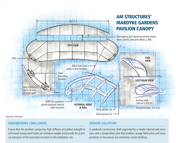
AM Structure's Mardyke Gardens Pavilion Canopy Illustration: Karl Reque
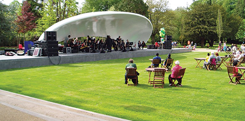
In Cork, Ireland’s Mardyke Gardens, the centerpiece of the city’s Fitzgerald Park, this new pavilion with a strikingly modern canopy will set the stage for musical and theatrical performances as well as outdoor cinema. Source: Gurit
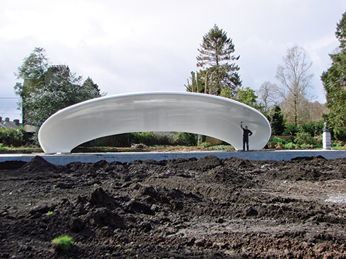
This unique shape of the pavilion canopy is constructed of glass-reinforced epoxy and designed to stand up to high wind loads and inclement weather. Source: Gurit
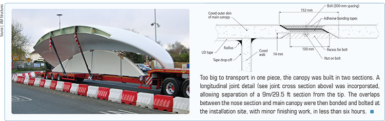
Too big to transport in one piece, the canopy was built in two sections. A longitudinal joint detail (see joint cross section above) was incorporated, allowing separation of a 9m/29.5 ft section from the tip. The overlaps between the nose section and main canopy were then bonded and bolted at the installation site, with minor finishing work, in less than six hours. Source: AM Structures


Engineering Challenge:
Ensure that the pavilion canopy has high stiffness and global strength to withstand strong wind loads, yet minimize weight and provide for practical transport of the oversized structure to the intallation site.


Design Solution:
A sandwich construction shell supported by a simple internal web structure, with a longitudinal joint that enables canopy fabrication and transportation in two pieces but minimizes onsite finishing.
The Irish city of Cork is hoping that its newly redesigned Mardyke Gardens in the city’s Fitzgerald Park will become an iconic attraction for tourists. The garden’s centerpiece is a new pavilion with a strikingly modern canopy, where the city will host musical and theatrical performances as well as outdoor cinema.
The canopy was conceived by Cunnane Stratton Reynolds (Cork, U.K.), a multidisciplinary consulting firm that handles urban and landscape planning. Its unique shape was informed by the park’s heritage, specifically its role as a venue for the 1902 Cork International Exhibition, a showcase for emerging 20th Century technologies and industries. Cunnane Stratton Reynolds’ design team says it “reimagined the gardens as a venue and destination fit for the 21st Century.”
Re-imagining the materials
“A shape like that just calls for advanced composites,” says Dr. Mark Hobbs, senior engineer, Gurit (UK) Ltd. (Isle of Wight, U.K.). But the initial design from Darmody Architects (Dublin, Ireland) called for a steel framework clad in either wood paneling or a fiber-reinforced plastic (FRP) shell.
Given that mandate, Isle of Wight-based AM Structures Ltd., a specialist in large-scale composite structure fabrication, subcontracted Gurit to engineer the shell’s materials solution. Having previously worked with AM Structures on large canopy structures, Gurit developed several glass FRP cladding solutions for the steel superstructure. “But we also began to consider a fully composite solution,” Hobbs recalls, noting, “Analysis on the composite shell showed that it possessed nearly enough strength and stiffness on its own, without the large steel work underneath to meet the structural requirements.” Several studies were performed to see if carbon reinforcement would be necessary, but in the end, it was clear, says Hobbs, “we could achieve sufficient strength and stiffness using just glass.”
Darmody and the team’s general contractor agreed that an all-composite solution would be beneficial. It not only eliminated the steel work and the associated bolts and connections, but it also reduced the canopy’s complexity, simplified its installation and ensured a longer service life. “With the GFRP solution, the entire structure was fabricated off site, requiring only minimum onsite installation,” says Hobbs. And, although the structure is large, its light weight allows for easy handling. “Overall, the FRP surface is cleaner, free of joints that would’ve been necessary with cladding, and the FRP provides excellent resistance to corrosion.”
Managing global and local loads
The composite solution was not without its challenges, however. “We had some reasonably tight stiffness and global-strength criteria to meet on the structure,” says Hobbs.
“We used the Eurocode standards to define the load and stiffness criteria,” explains Gurit design engineer Francois Hilary. “Stiffness criteria is a maximum deflection of 1:200 over the serviceability limit states, and the strength criteria are checked over a variety of different envelope load cases for short-term and long-term loading.”
Gurit relied heavily on analysis tools in Hyperworks from Altair Engineering Inc. (Troy, Mich.) to define the load paths and ensure that reinforcements would be properly placed to get the loads to the base. “FEA permitted us to have a clear view of how the structure was responding to the different loading from the first simple models, so we were pretty confident regarding the load paths,” says Hilary. Using Altair’s Hypermesh, the structure was optimized for global deflections and natural frequency, strains under serviceability limit state (to avoid microcracking of the resin) and strength under ultimate limit states.
The primary load, however, was aerodynamic. “We had a global wind load of 1.8 kN/m2, which is suction load,” says Hobbs. “Because the structure is essentially shaped like a parasail, it has a tendency to want to lift up off the base. And since it’s a very light structure, we needed to consider not just the uplift, but also the downward weight on the structure,” he adds. The GFRP structure’s surface area is just under 100m2/1,076 ft2 with a total mass of 3.5 tons. “At a maximum, we’re dealing with approximately 16 tons of uplift, which is quite a lot of load,” explains Hobbs. “We wanted to move that load down to two “feet,” each fitted with two steel brackets, on either side of the shell, that are fixed into the concrete.” The four brackets bear both uplift energy and downward loads.
The inner and outer shells ultimately were conceived as quadraxial laminate-skinned sandwich constructions. Quadraxial reinforcements would compare well to the initial design, providing equal strength in all directions in the same way as steel, and offered good performance predictability. Skins were formed with Gurit’s Ampreg 21 FR epoxy and glass fibers at 0°, 90°, +45°, and -45° on either side of Gurit’s trademarked Corecell M80 SAN foam core. Corecell M, says Gurit, combines high shear strength (1.09 MPa/158 psi) with low density (81 to 89 kg/m3/5.1 to 5.6 lb/ft3), high elongation, high-temperature resistance, and low resin uptake. Additional UD tapes placed inside the outer skins would add global stiffness to the structure. The number of UD tapes and tape drop-offs were optimized using FE analysis.
Inside, the shell would feature a set of internal ribs and webs. “These were mainly for support of the shell itself under panel deflection, but they also direct the global loads from the shell down towards the two steel feet on either side of the structure,” explains Hobbs. Those “feet” — via the steel brackets (see foot detail in drawing, top left) — would be bolted to the webs and then connected to the concrete plinth that forms the foundation for the canopy. Core in the internal web was replaced by solid E-glass laminate locally, at the bolting points, to provide bearing strength in the laminate sufficient to transfer load into the bolts.
“To keep the internal structure simple, we decided to make the webs out of flat panels rather than having to mold a curved structural beam,” says Hobbs (see drawing). “By simplifying the internal support structure, it was easier and quicker to manufacture the components, and saved the cost of tooling.” Rhino 3D modeling software from McNeel America (Seattle, Wash.) was used, says Hobbs, “to complete work within the 3-D geometry in order to achieve these simple, but effective webs.” Further, he says, “Geometry and laminate of internal webs was also optimized using FEA to achieve a good balance between structural efficiency and ease of manufacture.”
The biggest issue, according to Hobbs, was to maintain the orientation of the internal webs as they neared ground level, says Hobbs, “to ensure that the base plate holes in the steel feet would match up to the anchors in the concrete slab.” The steel feet would be bolted into the structure in the factory, which meant that early communication between Gurit and AM Structures and the contractor laying the concrete base was critical.
“Simple preliminary FE models were run and compared until we were happy with the internal structure disposition,” says Hilary. “Then the final laminate and UD reinforcements were optimized using FEA as well to ensure compliance with Eurocode.”
One complication was that a one-piece canopy would be too massive to move by truck. “We looked at a number of ways to split up the structure,” says Hobbs. Eventually, it was determined that a 9m/29.5-ft section from the forward uppermost curve of the canopy would be fabricated separately. It and the main canopy structure would have molded-in overlaps at the joint line, to facilitate bonding and mechanical fastening.
Design for “simple” manufacture
After design approval, its components were wet laminated, vacuum consolidated and cured on very simple tooling. “Both the upper and lower shells were manufactured alongside each other over a timber-and-ply former, with care taken to assemble the longitudinal accurately to match the precast foundation already on site,” says Downer. Webs were formed on flat tables and then cut and bolted into the structure. The outer shells, with UD tapes in place, were then bonded onto the web structure to form the completed canopy.
“Incorporating a longitudinal joint detail that enabled the transportation of the pavilion from AMS to the job site with a minimum amount of onsite finishing work was a definite challenge,” quips AM Structures director Mark Downer, but he points out that the joint enabled onsite joinery in less than six hours. The structure was finished with International Interthane 990 acrylic polyurethane, from AkzoNobel Marine & Protective Coatings (Gateshead, U.K.).
Hilary likens the canopy design and engineering process to that used in previous sailboat and tidal and wind turbine projects. “The beautifully curved shape made the study interesting,” he says. “However, the overall construction methods and design were standard,” he adds. “The sandwich construction permitted us to use a very simple internal structure design, and it was easy to build and assemble.”
“In fact,” Hilary concludes, “this is a school case of how switching to composites saves money and time and solves potential problems.”


.jpg;maxWidth=300;quality=90;format=webp)


Related Content

CirculinQ: Glass fiber, recycled plastic turn paving into climate solutions
Durable, modular paving system from recycled composite filters, collects, infiltrates stormwater to reduce flooding and recharge local aquifers.
Read More
Price, performance, protection: EV battery enclosures, Part 1
Composite technologies are growing in use as suppliers continue efforts to meet more demanding requirements for EV battery enclosures.
Read More
Materials & Processes: Composites fibers and resins
Compared to legacy materials like steel, aluminum, iron and titanium, composites are still coming of age, and only just now are being better understood by design and manufacturing engineers. However, composites’ physical properties — combined with unbeatable light weight — make them undeniably attractive.
Read More
Materials & Processes: Fibers for composites
The structural properties of composite materials are derived primarily from the fiber reinforcement. Fiber types, their manufacture, their uses and the end-market applications in which they find most use are described.
Read MoreRead Next

Bus station pavilion: A marriage of design and manufacture
Architectural design studio and boatbuilder cooperate to make this passenger terminal "first" a first-class showpiece.
Read More
Event pavilion: SMC panels ensure architectural authenticity
To expand its services, the High Bullen golf and spa hotel in Devonshire, U.K., converts a little-used tennis facility into a flexible meetings facility, and kept the remodeled structure within the local "heritage" code with simulated mortared stone-like composite panels from Acell Industries Ltd. (Dublin, Ireland).
Read More
Bus station pavilion: A marriage of design and manufacture
Architectural design studio and boatbuilder cooperate to make this passenger terminal "first" a first-class showpiece.
Read More