
Materials & Processes: Composites part design
Designers of composite parts can choose from a huge variety of fiber reinforcements and resin systems. That makes knowledge of how those materials work together a critically important aspect of part development. Here's a short description of what that knowledge entails.


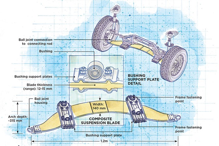
Industrial transportation supplier Hutchinson (Paris, France) developed front and rear axles made from glass-reinforced composites for the Peugeot 208 FE, a hybrid electric concept car. The switch from a traditional metal axle/suspension system to one based on composites resulted in a weight savings of 20.4 kg. See more composites part design examples at compositesworld.com/hashtag/focusondesign. Illustration | Karl Reque
Designers of composite parts can choose from a huge variety of fiber reinforcements and resin systems, a situation that gives infinite design freedom but adds to composites’ complexity. Knowledge of material properties is a prerequisite to satisfactory product design, but cost is a major factor, as well. Overdesigned composites cannot compete with lower-cost, established material systems. A well-designed part that uses composites’ anisotropy not only employs the right materials and processes to meet application requirements but, many times, can be commercially competitive with a product made with competing materials that are less expensive in terms of raw material cost (steel, aluminum, etc.), when installation and lifecycle costs (maintenance, repair, the impact of a longer useful life) are considered.
In any design, the fiber reinforcements provide the greatest portion of the composite’s mechanical properties, such as stiffness and strength, while the matrix — a polymer resin or an alternative, such as a ceramic — provides physical characteristics that can include toughness and resistance to impact, weather, fire, ultraviolet (UV) light and/or corrosive materials.


Three additional factors must be considered when designing with fiber: fiber type, fiber form and fiber orientation or architecture.
A significant design consideration is fiber-to-resin ratio, which is a determining factor in the ultimate weight and cost of the component and governs the extent to which performance properties inherent in the fiber reinforcement can be optimized in the part. Fiber-to-resin ratio can range from 20:80 for low-cost, nonstructural components to as high as 70:30 in some high-end structural parts. A 60:40 or higher ratio is common in advanced composites.
Three additional factors must be considered when designing with fiber: fiber type, fiber form and fiber orientation or architecture. Orientation refers to fiber direction in relation to the longest part dimension. Typically, fiber architecture is tailored in the direction of the primary loads placed on a structure, a design principle comparable to what civil engineers use to orient steel reinforcing bars in a concrete structure. Common orientations are unidirectional (longitudinal or 0°), cross-ply (90°) and angle or off-axis plies (usually ±33° to ±45°). However, fiber orientations also may vary from these more common orientations, depending on the particular applications. Angle plies carry shear loads, and are necessary to reinforce unidirectional, longitudinal plies. Angle differences between plies should be minimized, that is, a stacking sequence should be [0°/45°/90°/-45°] rather than [0°/90°/45°/-45°] to minimize interlaminar shear stresses caused by the anisotropic plies.
For example, in filament winding processing, a 54° winding angle satisfies both the circumferential (hoop) and longitudinal (axial) strength requirements of most pipes and pressure vessels. However, if more stress is placed on the pipe in the axial direction, as is the case with an unsupported span, a ±20°/±70° fiber orientation will provide a stiffer bending modulus for increased axial strength.
Composites, by nature, enable designers to tailor fiber architecture to match the performance requirements for a specific part. Laminates may be designed to be isotropic (with balanced stacked laminates to imitate the performance of legacy materials) or anisotropic, balanced or unbalanced, symmetrical or asymmetrical — depending on the in-use forces a component must withstand (italicized terms are defined in our “Glossary of Terms”).
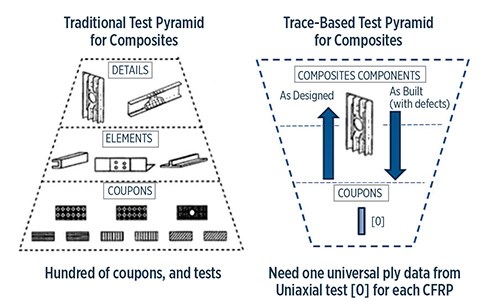
This graph shows traditional and Trace-based testing strength pyramids. By adopting a trace and master ply material model, the cost of testing CFRP materials and structural components reportedly can be greatly reduced. Significantly reduced numbers of coupons can be tested. Only basic uniaxial testing is required to characterize any CFRP material, using stiffness and strength invariants, which makes a testing program much more affordable and very similar to testing of metals. Additionally, trace can help in quality assurance processes, enabling test personnel to quantify variations attributable to material quality or the manufacturing process by testing components. Source | CompoSIDE Ltd.
One development in laminate design has been proposed by Dr. Stephen Tsai of Stanford University, in collaboration with other researchers, who has shown that a “bi-angle” laminate, one with alternating stacked layers of unidirectional fibers and angle plies at a shallow angle of less than 45°. Tsai says that when the angle is reduced in relation to the 0° direction, optimally at about 20°, the resulting laminate withstands significantly greater stress before first-ply and last-ply failure and generally performs better in many load applications, thanks to the reduction in interlaminar forces. Concern that very low-angle cross plies might result in “potato-chip warping” of the laminate is alleviated, says Tsai, if enough thin layers are stacked together. (Read more about it in “Bi-angle fabrics find first commercial application”.) This design concept is the result of Tsai's work with trace-based CFRP design and testing. Trace is, in essence, a simple invariant of tensorial transformation in matrix algebra and is a fundamental parameter for composite materials. The research revealed that stiffness and strength data for all modern carbon fiber/polymer composite laminates converge to almost identical values if normalized by their respective stiffness trace. This universal stiffness means that a master ply and simple scaling by means of material trace can be used to dimension laminate parts, just like they can for homogeneous materials. (Master ply is trace-normalized material which is shared for CFRP materials and the trace of this material is equal to 1. See "Overnight design allowables? An invariant-based method for accelerating aerospace certification testing". Additional details on how this research has been developed for practical application in design has been discussed in CW by Radek Michalik (CompoSIDE Ltd., Cowes, Isle of Wight, UK) in his article "CompoSIDE and Trace: Game-changer for development of composite parts.")
An understanding of layered or laminated structural behavior is vital to effective composite component design. Adhesion between laminate layers (called plies) created by resin wet-out is critical; poor adhesion can result in delamination under stress, strain, impact and/or other load conditions.
Ply layup designers must consider mechanical stresses/loads, adhesion, weight, stiffness, operating temperature and toughness requirements, as well as variables such as electromagnetic transparency and radiation resistance. Using composites, a designer has freedom to vary fiber orientation and adjust the number of ply layers at any point in a laminate to meet local performance requirements. Wall thickness, for example, can be varied, thicker where stresses or loads are high, caused by a fastener or metallic attachment, and thinner where they are low. This makes it possible to minimize weight and realize complex shapes and produce large parts with integral reinforcement.
Additionally, composite component design must account for the desired surface finish (cosmetic gel coat, for example), fatigue life, overall part configuration, and scrap or rework potential, to name just a few of the many applicable factors.
The intended fabrication method also will influence design. For example, manufacturers of filament-wound or tape-layed structures use different reinforcement forms and buildup patterns than those used either for laminate panels layed up by hand or for autoclaved prepreg parts. Resin transfer molding (RTM), which is one of several processes that employs a two-piece, fully enclosed mold, requires three-dimensional preforms as compared to other manufacturing techniques. Preforms must be designed to give the finished parts the appropriate fiber architecture, without moving during the resin injection step. RTM, in fact, is capable of producing a part with a predictable finish on 100% of its exposed exterior surface. It is also capable of producing complex 3D parts. For example, hollow parts with at least one opening can be made in one piece, with a finished surface on both exterior and interior, through the use of removable (collapsible or inflatable) inner tools called mandrels. The choice of production method and type of tooling must be made with part desired geometry, aesthetics, part performance requirements and production run length in mind (see "Fabrication methods" and “Composites 101: Tooling”).
A common type of composite structure — sandwich construction — combines a lightweight core material with thin laminated composite skins (facesheets), similar to the construction of corrugated cardboard. These cored panels have the highest stiffness-to-weight and strength-to-weight performance of all composite structures and are extremely resistant to bending and buckling, as determined by core thickness and skin architecture. Suitable core materials include closed-cell foams, balsa wood and celled honeycomb in a variety of forms (aluminum, paper or plastic). Some foam cores are syntactic, that is, they contain hollow microspheres to reduce weight. Sandwich construction is used extensively on modern aircraft and boats as well as in applications such as cargo containers and modular buildings.
Some material suppliers offer reinforcements with an integral core, such as a core-like material (e.g., foam rods) stitched together with glass or carbon fibers. This combination — a woven or unidirectional fiber form integrated with a core material — provides a unitized composite structure that is amenable to both infusion and closed-mold processing.


.jpg;maxWidth=300;quality=90;format=webp)


Related Content

Plant tour: Albany Engineered Composites, Rochester, N.H., U.S.
Efficient, high-quality, well-controlled composites manufacturing at volume is the mantra for this 3D weaving specialist.
Read More
Materials & Processes: Tooling for composites
Composite parts are formed in molds, also known as tools. Tools can be made from virtually any material. The material type, shape and complexity depend upon the part and length of production run. Here's a short summary of the issues involved in electing and making tools.
Read More
Novel composite technology replaces welded joints in tubular structures
The Tree Composites TC-joint replaces traditional welding in jacket foundations for offshore wind turbine generator applications, advancing the world’s quest for fast, sustainable energy deployment.
Read More
MFFD thermoplastic floor beams — OOA consolidation for next-gen TPC aerostructures
GKN Fokker and Mikrosam develop AFP for the Multifunctional Fuselage Demonstrator’s floor beams and OOA consolidation of 6-meter spars for TPC rudders, elevators and tails.
Read MoreRead Next

Materials & Processes: Introduction
High strength at low weight remain the winning combination that propels composite materials into new arenas, but other properties are equally important. This article outlines the case for composites and introduces SourceBook's overview of the materials and processes used to make them.
Read More
CW’s 2024 Top Shops survey offers new approach to benchmarking
Respondents that complete the survey by April 30, 2024, have the chance to be recognized as an honoree.
Read More
Composites end markets: Energy (2024)
Composites are used widely in oil/gas, wind and other renewable energy applications. Despite market challenges, growth potential and innovation for composites continue.
Read More