
Nondestructive Testing Broadens Its Scope
Automation and integration of advanced NDT methods lead to faster, more accurate flaw and damage detection.


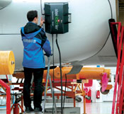
Source: Steinbichler Optotechnik GmbHPortable laser shearography is used to inspect aircraft components at Airbus Industrie (Toulouse, France).
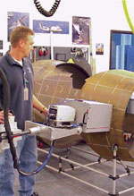
Source: Thermal Wave Imaging Inc.Thermographic tests of components for engine nacelle packages help fabricator Nordam identify manufacturing defects accurately and efficiently.
As the newest generation of composites-intensive aircraft comes online — notably Boeing's 787, and Airbus' A380 and A350 — nondestructive testing (NDT) of composites will assume unprecedented importance, in aircraft manufacture and maintenance/repair. NDT refers to the family of test methods that evaluate the material integrity of a laminate (as opposed to its performance or functionality) by detecting subsurface flaws without damaging the test article. NDT techniques involve the use of a device that can send and then detect changes in a signal that is either transmitted through a laminate to a receiver on the opposite side or reflected back to the sending device from subsurface constituents of a composite component. Changes in signal characteristics occur as the signals encounter anomalies in subsurface conditions — specifically, flaws such as cracks, disbonds, porosity, voids or foreign objects. These changes are interpreted by a variety of means that help operators identify flaw location, type and size.
NDT methods currently used in aerospace applications span an unusually broad range of technological sophistication, from the simple coin tap test to automated, computerized technologies that can conduct inspections of large parts entirely without human intervention. Today, aerospace manufacturers and maintenance/repair organizations continue to use them all, and appropriately so, says Abaris Training Resources president Michael Hoke, whose Reno, Nev.-based staff is redesigning the company's training courses for 2007 to reflect the changing NDT climate. "None of these techniques will find everything," he points out, "and conversely, all of them will miss some things."


NDT consultant and trainer John Register of R-Con NDT Inc. (Menomonie, Wis.) contends that "NDT is just catching up" to the growth that composites have experienced in aircraft applications.
Sound and light
NDT methods used with composites can be grouped in two broad categories, those that inspect laminates using sound technology (sonic or ultrasonic), and those that take advantage of the physics of electro-magnetic energy, such as infrared radiation (heat) and visible light.
Methods in the sonic/ultrasonic category transmit and read changes in vibration frequencies, amplitudes and/or transmission speeds. Sonic test methods (that is, those that produce and evaluate audible sound) involve some variation of the traditional tap test. As the name implies, a tap test literally involves tapping the composite structure while listening for changes in the sound caused by the presence of flaws. Tap testing is a viable option for many carbon-reinforced components, says R-Con's Register, "as long as you understand its limitations." Sandwich constructions with laminate skins of 12 plies or fewer are most conducive to tap testing, he adds.
Ultrasonic testing devices generate and evaluate signals in frequencies too high to be audible (typically, from 50 kHz to 100 MHz). A transducer generates the ultrasonic signal at the composite structure's surface. These systems send and receive signals in one of two ways: In pulse-echo systems, the sending transducer also is designed to detect the signal as it is reflected back from the composite subsurface. In through-transmission systems, by contrast, a sending transducer generates the signal at one surface of the structure, while a receiving transducer on the back surface of the structure detects the signal after it has traveled through the structure. In either case, the received signal varies in amplitude, depending on what it encounters within the composite structure.
Two types of ultrasonic method are used in NDT of composites: A-scan and C-scan. A-scan is the simpler method, typically employing a handheld transducer unit, using the pulse-echo technique. It measures the amplitude of the sound waves as they change in time. Technicians observe the wave amplitude on an oscilloscope. Spikes or drop-offs in the amplitude indicate defects. By contrast, the C-scan method employs varying degrees of automation, and can be set up to do pulse-echo or through-transmission scans, using a computer-generated raster scanning pattern; that is, the ultrasonic transducer is mechanically and systematically moved over the entire part surface, taking readings at regular intervals. C-scan units digitize a set of collected signals, which can be used to produce a visual representation of the subsurface, reducing the need for user interpretation. Register says, "It's like giving the user 3-D glasses, as opposed to monitoring the amplitude spikes of an A-scan." Such images can help the inspector distinguish, for example, between a point where poor wetout occurred and a point where a piece of backing material was left in the structure, both of which simply produce an amplitude spike on an A-scan.
Electro-magnetic methods make use of energy from the electro-magnetic spectrum, which includes visible light, infrared and ultraviolet energy and radio waves. The techniques and equipment range widely in cost and sophistication. Many technicians still use relatively simple, inexpensive light tables, which help them spot bulges and other surface changes created by subsurface flaws in composite structures in applications that have a relatively high tolerance for large subsurface defects. "We preach visual inspection for many glass-reinforced components," Register notes, "but carbon typically requires other techniques."
Those techniques include two methods on the opposite end of the cost spectrum, which today offer the fastest and most sophisticated NDT testing available. One is thermography, which uses infrared energy to heat a laminate so that infrared sensing technology can read variations in the heat emitted from voids and other subsurface anomalies, which absorb the heat energy at differing rates than the rest of the laminate.
The other method, laser shearography, reads light reflected from a laminate by a scanning laser. In the shearographic technique, stress is applied to the laminate, which alters the surface elevation of the entire structure, but the change in elevation differs over a defect compared with the rest of the structure. Laser shearography detects these changes as shifts in the phase of the reflected laser light pattern. Systems using this method can be very sensitive, detecting, for example, surface changes created by tiny changes in applied stress — an increase of 1 psi in a 5000-psi pressure vessel.
The following new products and continuing research efforts offer manufacturing and maintenance personnel tools designed to keep pace with composites growth, especially as carbon composites are employed in load-bearing aircraft structures.
Automated tappers
While tap tests can be done with a small object, such as a coin, with a reasonable degree of reliability, this simplest and least-expensive method has given way to tap methods with a high degree of sophistication that do not rely on a technician's practiced ear. For example, the Rapid Damage Detection Device (RD3) from WichiTech Industries (Columbia, Md.), consists of a lightweight hammer with an accelerometer, which measures the speed at which the hammer bounces off the structure (slower bounces indicate flaws). The device is cable-linked to a liquid crystal display, where numeric readouts correlate to delaminations and other flaws. Similarly, the Woodpecker from JR Technologies (Royston, U.K.) uses built-in sensors with a solenoid hammer to display quantified delaminations.
Ultrasonics for composites
While the high-frequency signals generated by ultrasonic systems work well on thin metallic structures, system adjustments must be made to adapt them for composites. Composites attenuate high frequencies — that is, they tend to absorb rather than transmit them. "For technicians used to metallic structures, it's a whole new world," Register says. "Composites require a lower frequency to penetrate through the material."
To transmit an ultrasonic signal into a composite structure, a coupling agent (typically, water) is used to avoid the attenuation that occurs in the air between the transducer and the structure. Immersion tanks and "squirters" are used to deliver the water.
For composite structures that cannot tolerate water exposure, air-coupled ultrasonics, such as the AIRSCAN technique developed by Quality Material Inspection Inc. (QMI, Huntington Beach, Calif.), have been addressing the attenuation issue since 1989, claims Walter Weber, president of UTEX Scientific Instruments Inc. (Mississauga, Ontario, Canada), a supplier of software and support to NDT system integrators. Weber explains that air-coupled ultrasonics can be used for not only surface mapping but bond detection as well. "It works for both."
AIRSCAN uses specialized trans-ducers, with frequencies ranging from 50 kHz to 400 kHz, to produce C-scan images in either through-transmission or pitch-catch modes. Goodrich (Santa Fe Springs, Calif.) uses AIRSCAN to perform multifrequency scans to inspect its carbon/carbon and ceramic matrix composite (CMC) aircraft brakes and other structures, which cannot tolerate moisture at the NDT assessment stage. "Our end-users are very concerned with product uniformity," explains Afshin Bazshushtari, Goodrich's engineering manager. "These materials are relatively expensive, and they are exposed to extreme environmental conditions, such as high heat or oxidizing atmospheres." Goodrich also feeds information from the scans back to its manufacturing engineers to improve initial processing. "AIRSCAN has helped us to more fully understand what we need to do to make the product more uniform," Bazshushtari says. "We've cut variation in half, and we provide products with a much narrower range of properties."
Significant developments in transducer and signal optimization also are enabling ultrasonics to move into previously impenetrable composite NDT applications. Generally, lower frequencies can penetrate more deeply, but higher frequencies provide better resolution. A wider dynamic range allows ultrasonic systems to get signals through highly attenuating, exotic core materials like aramid honeycomb, UTEX' Weber says.
The company has helped implement "pulse-compression" techniques that increase an ultrasonic system's dynamic range beyond the 100 dB limit typical of standard ultrasonic pulsers. Weber explains one technique, called chirp filtering, in which the signal is swept through a range of frequencies. The chirp filter is a digital signal processor that sorts out the returning signal by frequency. This additional degree of signal differentiation adds another 40 dB of dynamic range, Weber says, thus increasing the signal being detected by a factor of 100. "With the added dynamic range," he says, "you're lowering the noise floor and can penetrate thicker or more attenuative structures."
Since it is difficult or impossible to access the opposite sides of many sandwich structures, ultrasonic equipment manufacturers have developed bond testers — devices that use frequencies much lower than typical ultrasonic devices — such as the S-21R model from Zetec Inc. (Snoqualmie, Wash.). These devices produce pressure waves that can penetrate thicker composite structures, using the pulse-echo method. Bond testers also usually offer a resonance mode, in which continuous signals up to 500 kHz affect the resonant frequency of the transducer and indicate a possible flaw when that frequency changes suddenly.
Aerospace industry users are taking advantage of several means to increase ultrasonic system utility, sensitivity, accuracy and speed. Since sensitivity for composite applications is directly proportional to transducer size, says R-Con's Register, a quarter-inch flaw requires a quarter-inch transducer. Given the large surfaces of aircraft parts, the industry is moving away from handheld, single-channel, single transducer units. These units depend entirely on a fatigue-prone technician for their scanning accuracy, during a slow, tedious process. However, a gang-array, in which signals from two to eight transducers in a holding device are multiplexed to the single channel, increases the scanning width. "But it becomes a task to make a single-channel instrument work with multiple transducers," Register cautions. Yet a basic A-scan, single-channel ultrasonic system is often the recommended system for local inspection of aircraft structures, Register insists. "The best tool these users need is training," he says. "Then, basic ultrasonics goes a long way."
Phased-arrays with 128 elements, typically 10 cm (4 inches) long, scan larger areas much more efficiently. "Scanning a four-inch area instead of a half-inch makes phased-array systems eight times faster than single-channel systems," Register says, "and with storage features and post processing capability, they give you more information for hard copy or analyzing data."
While these systems reduce the human factor, he points out that "the investment jumps from under $20,000 to $100,000 or more." The additional cost can be justified, however, especially when a user must perform repetitive testing on large parts.
Robotics
For exceptionally large parts and production volumes, the next step up is a gantry system. These employ computer-controlled robotic systems to perform automated scans, eliminating the chance of leaving areas unscanned, but are limited to end-users who can invest $500,000 to $2 million, Register says. Such systems become almost indispensable, UTEX' Weber notes, when one must inspect multiple composite airframe components with integral stringers. "Traditional raster scanning is fine for relatively flat panels," he explains, "and basic robotics effectively follow complex contours, but with integrated I-beams or hat-channels, from the machine's perspective, there's no rhyme or reason to the path it must follow." Sometimes, he continues, the NDT equipment must get into corners or scan surfaces that move from vertical orientation to 45° and back again, for example. For such complex inspections, UTEX provides its InspectionWare software development platform. Weber says that InspectionWare can be used by a third-party system integrator or by the system integration team at a major manufacturing or maintenance facility to program an easy-to-use graphical control panel that enables NDT operators to run sophisticated inspection patterns. The platform features drag-and-drop tools, so that integrators need not write individualized software. InspectionWare can direct a gantry through the complex path required for components with integral stringers. The platform also supports "almost all third-party NDT products," Weber asserts. "If an NDT instrument breaks down," he points out, "the ability to select a different instrument from an approved vendor, allows the facility to continue its inspections."
Gantry alignment, however, is a critical challenge, especially as part geometry grows in complexity and the size of an acceptable flaw shrinks. "The quality of the ultrasonic image we collect is dependent on the testing machine's ability to follow itself and the complex-contoured geometry it's inspecting," explains Ken Bishop, president of Matec Instruments (Northborough, Mass.). Matec builds gantry ultrasonic systems for through-transmission inspection of composites, including components built by Lockheed Martin (Lufkin, Texas) for the F-35 Joint Strike Fighter (JSF). The sending and receiving transducers, mounted on two arms that work in a master-slave relationship, must maintain excellent orthogonality (alignment of devices with respect to each other and the signal direction). Yet the gantry drives, by their nature and because of machine wear, cannot ensure such exact positioning. Therefore, Matec uses a FARO Laser Tracker coordinate measuring system (FARO Technologies, Orlando, Fla.) to map the exact position of its gantry arms and produce a compensation table, or map, of the true position compared to the drive position throughout the machine's envelope. "This is analogous to the corrective data on a pilot's map that enables him to reset his magnetic compass at various locations," Bishop explains. Matec recalibrates with the Laser Tracker during maintenance operations on its machines, and the compensation table is adjusted, thus accounting for positional changes due to machine wear. The result, Bishop claims, is "phenomenal image quality."
Fully automated ultrasonics
BAE SYSTEMS (Samlesbury, U.K.) NDT specialist and section leader Dr. John Smith reports recently enlisting Ultrasonic Sciences Ltd. (USL, Aldershot, U.K.) to help develop and install a 17-axis ultrasonic scanning system for inspecting access panels, skins and spars with highly complex curvatures, which require inspection prior to being assembled into the JSF's fuselage subassemblies. Smith's team was charged with finding cost-effective means to detect manufacturing flaws of about 4 mm by 4 mm (0.16 inch by 0.16 inch) while scanning at linear speeds of 500 mm/sec (20 inches/sec).
The USL system meets these requirements while also providing direct interface to BAE SYSTEMS' manufacturing software. "The scanner takes its scan path trajectory information directly from our CATIA CAD data," Smith explains. "By using an NC machining package, we are able to output the coordinates to the USL software that creates the scan path." The USL system uses two independent, 5-axis manipulators to hold the send and receive transducers. An additional five axes of manipulation automate generic component location fixturing, and the two remaining axes are configured to control waterjet flow as the machine negotiates complex curvatures. Starting with CAD coordinates, USL developed software that appropriately applies to real-world coordinates on the components, compensating for component deviations and for small mechanical errors, as well as ensuring proper alignment of the transducers on either side of the component as they travel along complex trajectories. "To date this has been our largest investment ever in NDT equipment," Smith says, "and its success has been due to the collaborative approach between BAE SYSTEMS and USL."
BAE SYSTEMS is currently automating the system's calibration procedures. Special programming, now under development, will enable operators to test the equipment with known signals, via software control, and monitor the results. "We then can automatically alter gain and other parameters," Smith explains, "and confirm that the data acquisition system is converting the incoming signals correctly." This will reduce setup time while enabling calibration prior to each component inspection.
Detection versus rejection
UTEX initially built its business by serving as a conduit of NDT solutions that were designed to address specific problems for particular manufacturers. In one instance, UTEX' UT Link miniaturized the entire ultrasonic instrument and placed it as close to the transducer as possible, greatly reducing or entirely eliminating the noise pickup created by cabling used to connect ultrasonic signal transducers to the instrument. UT Link is small enough to be mounted directly on a gantry head. The reduced noise floor and, thus, wider dynamic range, "allows most composites to be inspected in one pass without the need for logarithmic amplifiers, which distort the signal and reduce amplitude resolution," Weber claims.
Another example is the frictionless ultrasonic gantry scanner built originally for Lockheed Martin (Palmdale, Calif.) by Resource Engineering Inc. (Tempe, Ariz.), with instrumentation and motion interfacing by UTEX. Called the Explorer, the scanner inspects production F-22 airframe components at a rate of 12 inches/sec (0.3m/sec). The gantry uses ultra-stable water columns for high-resolution ultrasonic images at full scan speeds. Special air bearings and highly stable gantry axes result in a reported accuracy of 0.001 inch (0.03 mm) anywhere within the scanning envelope.
With such capabilities available, NDT inspectors now have the means of detecting even the most subtle material variability, Weber contends. Image filtering software, he continues, aids such NDT systems in differentiating true flaws and foreign objects from the scatter created by the composite structure itself, such as places where plies may be butted. He notes that one system recently detected previously missed, subtle variation in a five-year-old reference panel — changes introduced when a coffee mug was placed briefly on the vacuum-bagged part prior to cure. "Customers don't necessarily want to see variations that are not rejectable," says Weber, "but we can dial in to the level of detection they want."
While inspection speed and accuracy multiplies when one moves from handheld A-scan units to gantry-mounted C-scan ultrasonic systems, it can grow exponentially with thermography and laser shearography. "Where an A-scan pulse-echo might have taken days, these imaging techniques might need only hours or even minutes," Hoke reports. And these techniques do not require backside access like C-scans often do.
Pulsed thermography
Thermography can be as simple as observing an object with an infrared camera while heating it with a lamp or heat gun. Variations in the infrared radiation are sensed by the camera and converted to a visible image, which maps the laminate interior. In aircraft manufacturing environments, however, far more sophisticated pulsed thermography systems use a very short, uniform pulse of light to heat the sample surface. Recent advances in pulsed thermography have improved both analytical methods and hardware, resulting in highly accurate quantitative results that clearly distinguish subsurface defects and measure physical properties, says Dr. Steven Shepard, president of thermography pioneer Thermal Wave Imaging Inc. (TWI, Ferndale, Mich.).
Mark Bors of aircraft component manufacturer and FAA-approved repair station Nordam Group (Tulsa, Okla.), uses a TWI system to inspect components Nordam makes for the engine nacelles on corporate jets. The components are made with a range of carbon reinforcements, from mat products to weaves, using either epoxy or bismaleimide resins. Thermography works especially well on Nordam's products, says Bors, because they are fairly thin — from 4 to 20 plies typically, or a laminate thickness of up to 5 mm/0.2 inch. The company is able to fully inspect an engine cowling door, a curved structure about 8 ft long by 4 ft wide (2.4m by 1.2m), in two to three hours, he reports.
To determine the depth of a defect, the system is calibrated against time, Bors explains: "A defect in the skin will show up sooner than a defect at the bondline. By comparing to the timing recorded from standards with known defects, we can locate defect depths down to the particular ply." Thermographic images also differentiate defect type; a void may appear white while a foreign object is darker than the surrounding structure. Bors concludes, "We've found that thermography is just as reliable as ultrasound, and the images seem cleaner and clearer."
Laser shearography
First used commercially in 1987 by Northrop Grumman on the B-2 bomber, laser shearography has emerged as an advanced, high-speed, high-performance technique that can detect changes in test part surface deformation, down to 5 nm. Applying very small changes in stress, such as a 1° increase in temperature, or a 1 psi increase in pressure, alters the surface elevation of the entire composite structure, but the change in elevation will differ over a defect, compared with the rest of the structure. Laser shearography detects these changes as shifts in the phase of the reflected laser light pattern. "We are able to detect small excursions from the nominal loaded condition of a composite structure and image subsurface defects in real time," says John Newman, shearography pioneer and president of Laser Technology Inc. (Norristown, Pa.).
Inspectors using early laser shearography systems were trained to visually observe the interference fringes created by the phase shifts (light and dark bands that appear when light waves interfere with one another). But
Newman says "phase-stepping shearography,"a major breakthrough in the 1990s, enabled generation of defect images, a feature important for exact sizing and location measurement. Further advancements in 2000, he recalls, dramatically improved software and solid-state laser diodes, helping to improve image quality and to lower system cost, size and weight.
Shearography also exponentially increases scanning speed. Newman reports inspections of F-22 fighter components can be conducted at the rate of about 500 ft2/hr, compared to about 10 ft2/hr possible with C-scan ultrasonics. Steinbichler Optotechnik GmbH (Neubeuern, Germany), maintains that even greater speeds and sensitivities are possible with its patented and trademarked Spatial Phase Shift measuring head. "All laser shearography systems rely upon separation and comparison of phase-separated optical images," explains Fred Perkins, Steinbichler's U.S. representative. "Our technology separates the phases spatially at the optical plane in a single exposure, while conventional shearography uses several exposures and physical changes to the optical path length to achieve the required phase separation." Steinbichler equipment is currently inspecting parts on the Airbus A380, using both stationary and portable shearography systems.
From inspection to health monitoring
According to Dennis Roach of Sandia National Laboratories (Albuquerque, N.M.), as sophisticated and efficient as the NDT techniques have become, advanced fiber-optic and other types of sensor technology may someday supplant many NDT applications by opening the door to in-situ "structural health monitoring." Installed on or within composite structures, such systems could continuously monitor even those regions of a component currently inaccessible to NDT equipment, detecting incipient damage and signaling when human intervention is required. This could eliminate the possibility of damage being overlooked and reduce costly downtime for manual inspections as well.
Moreover, Sandia's Airworthiness Assurance NDI Validation Center is investigating how to detect weak adhesive bonds, before they disbond. Abaris' Hoke points out, "Adhesive bonds degrade slowly over time and are highly dependent on surface preparation. There is no way to see where a technician may have sneezed before applying the adhesive until that area disbonds." On a 20-year-old aircraft, therefore, the only gauge for bond integrity is age, environmental exposures and statistics — not the actual condition of bonds. To manage such uncertainty, Hoke says, manufacturers have traditionally replaced life-limited items regardless of their inspected condition. "But that's easier to cost-justify with a helicopter rotor blade than with a wing on a 787," he quips.
Hoke is optimistic that weak-bond detection will be commercialized in the not-too-distant future. "The use of structural composites is increasing so fast that the need for NDT technology and trained technicians is growing at a rapid rate."


.jpg;maxWidth=300;quality=90;format=webp)


Related Content

Twenco develops sensors for smart molds and process control in resin infusion and composites welding
Non-invasive DEA and NDT Analyzer for multi-parameter monitoring, QA and control, including real time simulation feed and 3D process visualization across and through composite parts.
Read More
Low-void, large-scale, high-volume 3D-printed composites
Among its many composites-related projects, Oak Ridge National Laboratory recently installed its first AMCM test cell, combining extrusion with compression molding for fast, low-void, low-porosity thermoplastic composite parts.
Read More
Fiberglass Cutting Operation at Hubbell’s Lenoir City Plant Moves to Automation
Automating fabric cutting operations saves Hubbell Lenoir City money and can produce composite products faster at less cost to support infrastructure expansion.
Read More
Large-format 3D printing enables toolless, rapid production for AUVs
Dive Technologies started by 3D printing prototypes of its composite autonomous underwater vehicles, but AM became the solution for customizable, toolless production.
Read MoreRead Next

Composites end markets: Energy (2024)
Composites are used widely in oil/gas, wind and other renewable energy applications. Despite market challenges, growth potential and innovation for composites continue.
Read More
CW’s 2024 Top Shops survey offers new approach to benchmarking
Respondents that complete the survey by April 30, 2024, have the chance to be recognized as an honoree.
Read More
From the CW Archives: The tale of the thermoplastic cryotank
In 2006, guest columnist Bob Hartunian related the story of his efforts two decades prior, while at McDonnell Douglas, to develop a thermoplastic composite crytank for hydrogen storage. He learned a lot of lessons.
Read More