
NASA/Boeing composite launch vehicle fuel tank scores firsts
Subscale 5.5m-diameter cryogenic tank demonstrator with innovative fluted-core skirt is formed via robotic AFP and cured out of the autoclave.
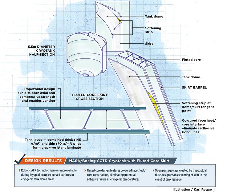
NASA/Boeing CCTD Cryotank with Fluted-Core Skirt. Illustration: Karl Reque
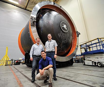
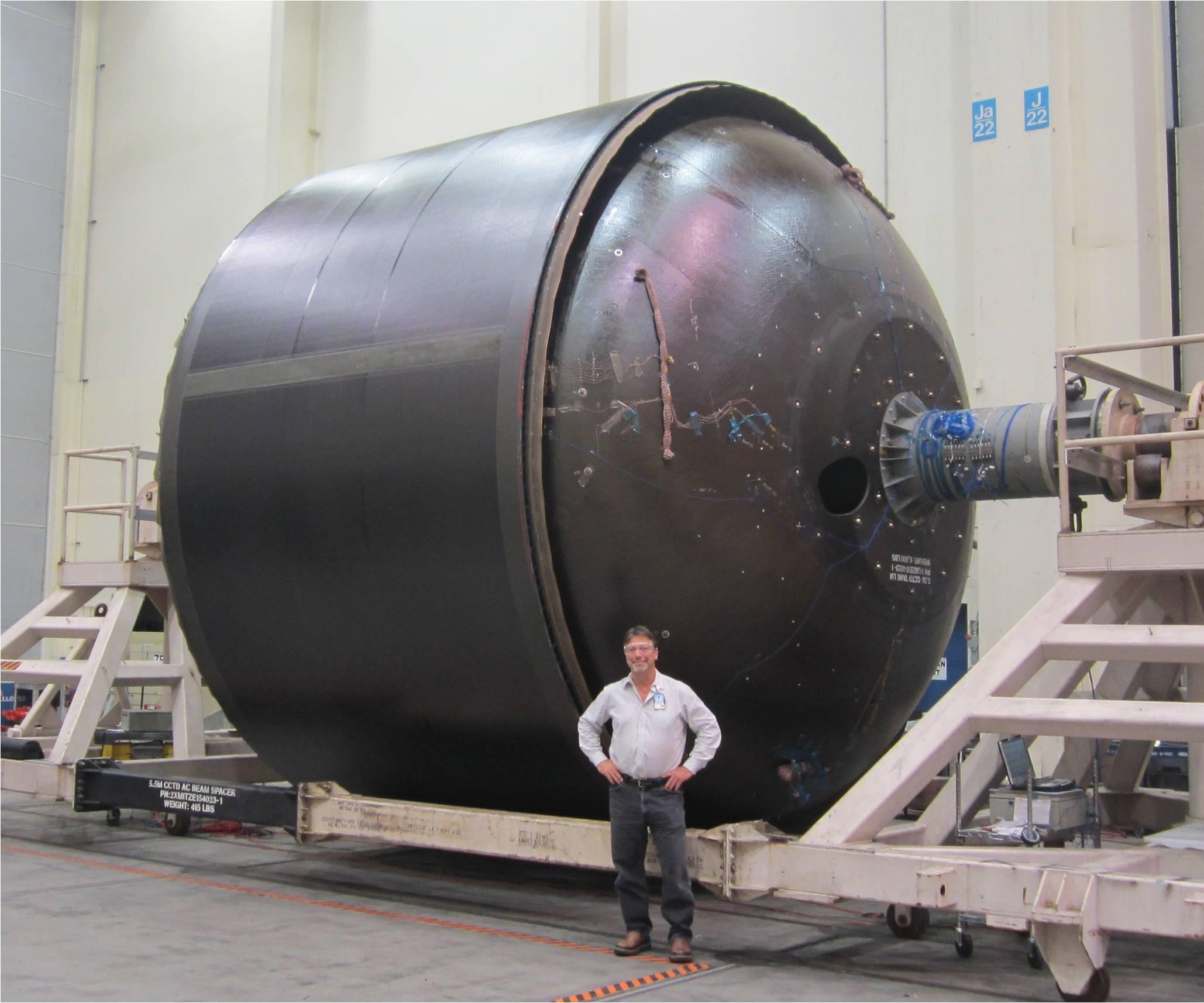
CCTD cryotank: Significant progress for composites: Douglas McCarville (top left), Brice Johnson (top right) and manufacturing R&D engineer Juan Carlos Guzman, (lower, center) of the Boeing Research and Technology project team pose with the finished subscale 5.5m composite cryotank demonstrator, completed in fulfillment of NASA’s Composite Cryotank Technologies and Demonstration project. The design, materials and manufacturing technologies are unprecedented and, says NASA and Boeing, are scalable to full-size tanks used on today’s launch vehicles. Source: Boeing R&T
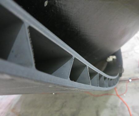
Co-cured construction: The CCTD skirt departs from conventional skirt sandwich constructions by linking its facesheets with a trapezoidal network of angled web members, and is fiber-placed onto the tank layup and then co-cured, leaving no adhesive bondlines to weaken at cryogenic temperatures. The fluted core also provides pathways to vent hydrogen in case of tank leakage. Source: Boeing R&T
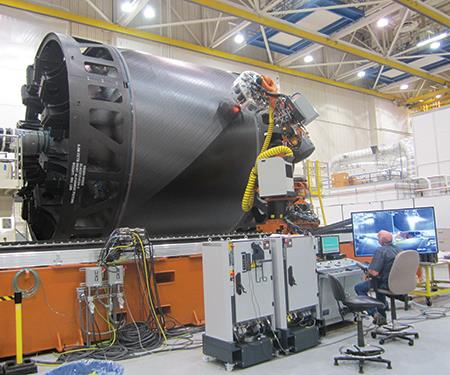
Robotic AFP meets manufacturing test: Boeing Research and Technology’s AFP system’s robotic arm and head-mounted fiber-delivery system resulted in a compact system capable of the necessary range of motion, layup accuracy and speed to meet engineering and material out-time requirements. Source: Boeing R&T
Co-cured tank and skirt: The assembled skirt and tank, after skirt co-cure was completed. Although the tank and skirt were judged a success, work will continue toward more practical tooling for the fluted core. Source: Boeing R&T


Design Results:
- Robotic AFP technology proves more reliable during layup of complex curved surfaces in cryogenic tank dome areas.
- Fluted core design features co-cured facesheet/core construction, eliminating potential adhesive failure at cryogenic temperatures.
- Open passageways created by trapezoidal flute design enables venting of skirt in the event of tank leakage.


For more than 50 years, heavy metal cryogenic tanks have carried the liquid hydrogen (LH2) and oxygen necessary to launch vehicles into space. But in a joint effort, NASA and The Boeing Co. (Chicago, IL, US) have designed, fabricated and tested a composite cryotank that, if scaled up to current space launch system dimensions, would weigh 30% less and cost 25% less than the best aluminum-lithium cryotanks used today, and could warrant transport of as much as 1,400 kg of additional payload to low-Earth orbit and beyond.
The US$25 million Composite Cryotank Technologies and Demonstration (CCTD) project, part of the NASA Space Technology Mission Directorate’s Game Changing Development (GCD) program, involved a team of Boeing and NASA engineers.
“This is the first effort to successfully build and test a tank of this scale,” says Douglas McCarville, Technical Fellow at Boeing Research & Technology (BR&T) in Seattle, WA, US. “The tank would work for liquid oxygen or liquid hydrogen on a variety of next-generation launch systems.”
The CCTD program goal was an inner tank that could contain pressurized LH2 at cryogenic temperatures, fitted with an outer skirt that could take the axial compression loads during launch-vehicle takeoff (see drawing, at left). Two cryotank demonstrators were built by Boeing and tested at the NASA Marshall Space Flight Center (Huntsville, AL, US). Final assembly of the latter was completed at the Boeing Developmental Center (Tukwila, WA, US) in April 2014.
Prior tank failure leads to fluted-core
The first tank, at 2.4m diameter, was fitted with a laminate skirt and tested in 2013. But the second, 5.5m-diameter CCTD tank, featured an innovative fluted-core design — a key part of the NASA/Boeing team’s response to lessons learned during previous composite cryotank projects.
Following a pressure test conducted Nov. 3, 1999, a large composite LH2 fuel tank built by NASA and Lockheed Martin (Bethesda, MD, US) for NASA’s half-scale experimental X-33 Venture Star space vehicle developed localized delaminations. The tank was filled with LH2 at -253°C to simulate mission-level pressures and loads, and the outer skin and honeycomb core debonded from the tank’s inner skin in one tank lobe. Although the inner skin was undamaged, several fractures were observed in the outer skin in the same lobe.
After extensive study, NASA determined that the delaminations were likely caused by a combination of factors. The inner carbon fiber/epoxy unidirectional tape facesheet, which was designed to prevent permeation of hydrogen into the carbon honeycomb core, was inadequate and had micro-cracked under the low temperature and load, allowing hydrogen to collect in the core cells. The ultra-cold hydrogen caused air in the cells to liquefy, which created a vacuum that pulled in purge gas from outside the core (a phenomenon called cryopumping). Cryopumping coupled with a degraded bondline between the inner facesheet and the core, a piece of polytetrafluoroethylene (PTFE) tape found on the core in the debond area, and other defects, contributed to the failure.
Significantly, the tank report noted that the results of the investigation did not invalidate the use of composite materials for cryogenic tanks. It was reportedly no surprise to the X-33 project’s engineers that the composite LH2 tank could fail during testing because there was little industry experience with large-scale composite structures. Despite the delamination incident, NASA and Lockheed Martin still believed in the promise of composites.
To prevent such delaminations in future composite cryotanks, the CCTD team, leveraging Boeing’s experience producing composites for aircraft, took several unusual steps. Instead of the gantry-based automated fiber placement (AFP) equipment classically used to build large cylindrical parts, Boeing opted to use robotic AFP. Boeing also trialed new materials that don’t require expensive autoclave curing, and it completely reconsidered its skirt design.
Prior to the CCTD tank, AFP heads with self-contained material spools on relatively low-cost robotic platforms were generally considered “right-sized” equipment for small, special jobs. The large fuselage and rocket component work went to traditional machines with an onboard creel. “Ironically, the robotic fiber placement system enabled improved capabilities — better reach in the dome areas and lower shaft clearance,” notes Brice Johnson, another Technical Fellow at BR&T. And robotic AFP, he claims, also can be scaled up to build the full-size 8.4m cryotank and skirt combination that would be required for NASA’s currently used space launch systems.
Boeing Research and Technology based its AFP system on a stock Kuka KR500 robot and controller (Kuka Robotics Corp., Shelby Township., MI, US). Its simplified fiber delivery path, enabled by the on-head spools, reduced issues with passing fiber through a highly articulated transport path. Its compact package permitted the necessary range of motion and demonstrated the layup accuracy and speed required to meet engineering and material out-time requirements. A key to tank fabrication was a collapsible, segmented mandrel that could be extracted after cure from an elliptical opening in the tank (for that story, click on "Janicki Industries: Breaking the Mold" under “Editor's Picks,” at top right).
Material-wise, the cryotank was made of Cytec’s CYCOM 5320-1 out-of-autoclave (OOA) prepreg, using a combination of thick plies (145 g/m²), which can be placed relatively quickly, and thin plies (70 g/m²), which create a micro-crack-resistant laminate that helps prevent hydrogen permeation, reports Dr. Jim Sutter, a composites expert at NASA Glenn Research Center (Cleveland, OH, US).
For the skirt design, says McCarville, “We needed something stiff and tailorable with low-temperature capability.” The Boeing team ruled out a honeycomb-cored sandwich structure because bondlines experience structural knockdowns at cryo-temperatures, McCarville explains.
Two alternative skirt designs also were considered and dropped. The first, skin/stringer construction, is used prevalently in commercial aircraft and involves laminate skins stiffened with longitudinal I-beam, T-beam or hat stringers. The second, isogrid structure, has upstanding legs that cross over each other in a gridwork pattern. “The fiber-reinforced laminate legs are typically 1 inch to 2 inches [25.4 mm to 50.8 mm] tall and look like a beehive with a rigid exterior,” McCarville says. Unlike honeycomb-cored and fluted-core panels, which have inner and outer facesheets, isogrids feature only an outer skin. McCarville says that on an 8.4m-diameter real-world tank, these options would be heavier than sandwich constructions.
In the end, the team adopted the fluted core, comprising large trapezoidal members — technically, laminate-angled web members with structural-radius fillers between facesheets (see photo at top left) because it can be optimized to efficiently take compressive launch loads and vented to prevent hydrogen buildup. Further, the skirt is a co-cured, unitized carbon fiber/epoxy laminate construction, so there are no adhesive bondlines that could degrade at -253°C cryogenic test temperatures. Subscale fluted-core components created during the coupon and joint-testing phase were shown to be stronger in shear and end-loaded compression, and were more damage-tolerant than conventional honeycomb designs. “With good bending stiffness, especially in axially loaded applications, the fluted core is considered a viable candidate for next-generation launch vehicle shells and skirts,” says McCarville, adding, “This type of construction, which resembles bridge truss structure, was determined to be the lowest weight construction option for the CCTD tank.”
During the build, tooling was assembled around the fiber-placed tank so that skirt plies and fluted core could be placed and co-bonded to the tank. Bonding the fluted-core skirt to the tank’s cylindrical dome tangent point required the integration of an arrowhead-shaped softening strip that had good shear, peel and expansion properties (visible in the drawing inset). “We developed a 3D polymer-infused carbon part that fit between the fluted-core skirt and the tank and remained compliant at low temperatures,” McCarville says.
Before the 34-month CCTD program ended, both the 2.4m and 5.5m tanks underwent full-scale, ground-based cyclical testing at cryogenic temperatures, including ambient and cryogenic pressure tests. Additional ground tests simulated pressurization plus flight loads — for these, axial/shear mechanical loads were applied through the skirts on the 5.5m tank. As a consequence of successful testing, “we raised the technology and manufacturing readiness levels from a level of 3 at the outset to 6 at the completion of the program,” McCarville says. The project produced the largest composite tank ever manufactured via AFP and then cured out of the autoclave. That said, challenges remain.
The next step: Real-world skirt tooling
On the 5.5m tank, relatively simple metallic end-fittings were used to join the constant cross-section flute trapezoids to the test stand. But on a launch vehicle, the flutes will require weight-efficient, possibly composite fittings that will most likely complicate flute geometry and, therefore, tooling.
“Fluted core, similar in shape to hat stringers, has hollows that need [structural] support during high-temperature cure,” McCarville explains. Further the tooling must support head pressures generated when the robotic AFP places the outer skin onto the flutes. During the CCTD program, Boeing used a proprietary prototype tooling method that was sufficient for constant cross-section flutes, but does not readily lend itself to real-launch vehicle end-fittings. “Now, we are working on designing end-fittings that allow for [post-cure] removal of a fluted-cure mandrel out of trapped volumes, as we will need for a real-world launch vehicle tank,” he says.
To address this challenge, NASA funded a Small Business Innovation Research (SBIR) contract on Tooling for Composites II - Fluted Core Demonstration. McCarville says, “That’s the function of small business innovation research projects like this, to help mature new innovative technologies that can be used to make next-generation products.”
CW will report on the results of the Fluted Core Demonstration research in its March 2016 issue.


.jpg;maxWidth=300;quality=90;format=webp)


Related Content

Carbon fiber in pressure vessels for hydrogen
The emerging H2 economy drives tank development for aircraft, ships and gas transport.
Read More
Vertical Aerospace eVTOL prototype goes down during uncrewed test flight
The U.K. company has confirmed the Aug. 9 accident that resulted in significant aircraft damage and potential setbacks.
Read More
Composites end markets: Aerospace (2023)
With COVID in the past and passengers flying again, commercial aircraft production is ramping up. The aerocomposites supply chain is busy developing new M&P for an approaching next-generation aircraft program.
Read More
Materials & Processes: Fabrication methods
There are numerous methods for fabricating composite components. Selection of a method for a particular part, therefore, will depend on the materials, the part design and end-use or application. Here's a guide to selection.
Read MoreRead Next

Janicki Industries: Breaking the mold
Once known only as a toolmaker, Janicki offers unique precision, production capability and problem solving as it pioneers leading-edge composites technology.
Read More
From the CW Archives: The tale of the thermoplastic cryotank
In 2006, guest columnist Bob Hartunian related the story of his efforts two decades prior, while at McDonnell Douglas, to develop a thermoplastic composite crytank for hydrogen storage. He learned a lot of lessons.
Read More
CW’s 2024 Top Shops survey offers new approach to benchmarking
Respondents that complete the survey by April 30, 2024, have the chance to be recognized as an honoree.
Read More