
Melding aesthetics with structure
A stairwell shroud recently installed on a Michigan university campus could be a bellwether for the expansion of composites into architectural applications previously considered out of reach.
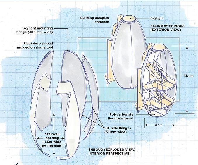
The CONSTRUCT/LTU Taubman Complex Stairway Shroud. Illustration: Karl Reque
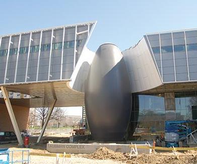
Egg-straordinary architectural composite: Located on the Lawrence Technological University campus (Southfield, MI, US), this 13.4m tall by 6.1m diameter wide, egg-shaped, glass/ phenolic stairway shroud serves both aesthetic and func- tional purposes. The central, eye-catching element between the Taubman Complex’s north and south wings and its main entrance protects stairwell occupants from rain, bears snow loads and is designed to withstand wind loads of up to 145 kph. Source: CONSTRUCT
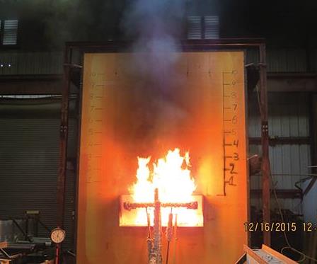
Fire-rated for four stories plus: Because the structure exceeds four stories in height, the building code required testing to the NFPA-285 fire/smoke performance standard for “high-rise” architectural structures. The test entails measuring the flame spread of this 6.1m/20-ft high panel, with an open window, comprising the laminate used in the construction of the shroud. Source: CONSTRUCT

Five panels infused from one tool: Each of the shroud’s five panels was fabricated via resin infusion at JRL Ventures (Cape Coral, FL, US), which also made the single tool used to mold the panels. Each panel was infused with phenolic resin in about 30 minutes, and cured at 65.5°C for 30 minutes, followed by a post-cure for 2 hours at 74°C. For mechanical connection of the panels, integral 90° flanges were molded on the sides of each panel with the aid of removable fences. Source: CONSTRUCT
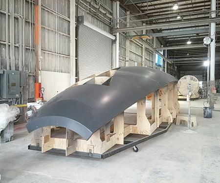
Class A + curvilinear = composite choice: One of the two opening panels is shown here, after coating with a water-borne acrylic paint. The requirement of a Class-A surface finish, along with the structure’s compound curvature, tilted the selection of the material for the shroud’s five panels in favor of composites, albeit one with structural properties. Source: CONSTRUCT


Design Results:
- This 13.4m/44-ft tall, glass-reinforced, egg- shaped shroud has a smooth surface finish and serves as both a functional entrance and central, architectural focal point between the building’s north and south wings.
- The shroud’s curvature and tight build envelope preclude a structural steel support skeleton, but its heavily axially oriented, non-crimp woven E-glass/phenolic laminate meets fire, wind and all other load requirements.
- The shroud’s dome-like shape distributes loads evenly in the plane of the shell, allowing design of a lighter, thinner structure than could be achieved with other architectural shapes.
Like other markets served by the composites industry, archi- tectural construction can be divided, broadly, into two categories: structural and nonstructural. That composites have been consigned to the latter has been the unwritten rule. CONSTRUCT, the South Carolina Research Authority’s architectural affiliate (Summerville, SC, US), recently provided the structural design and oversight for the manufacture and installation of a 13.4m tall by 6.1m diameter (44 ft by 20 ft), egg-shaped composite stairwell shroud that could overrule that assumption. Installed this spring as part of an expansion at the Taubman Complex at Lawrence Technological University (LTU, Southfield, MI, US), the shroud’s tall, curved profile and black surface finish form an eye-catching element where the engineering and science center’s north and newly built south wings converge. But beyond its aesthetic appeal, the massive structure is functional, protecting the stairway and the people who use it from rain, accumulations of snow and wind speeds of up to 145 kph.
The shroud’s and south wing’s aesthetic design was provided by Morphosis Architects (Culver City, CA, US), founded by the renowned architect Thom Mayne, a firm known for designing buildings with flowing organic lines and shapes, such as the Bill and Melinda Gates Hall at Cornell University (Ithaca, NY, US). Albert Kahn Associates (Detroit, MI, US), the architect of record, was responsible for implementing the design and specifying design and construction criteria, including local building code compliance, aesthetic and functional details, fire performance requirements and structural loading performance criteria on the installed stairway shroud. The latter included live/dead-weight, vertical-snow, lateral-wind and seismic loads. DeMaria Building Co. (Detroit), serving as the general contractor, was CONSTRUCT’s direct customer.
CONSTRUCT’s general manager, David Humphries, says his company employs an iterative, multi-step “design assist” process as its standard. It begins with a review of the design specifica- tions and compliance requirements, and then proceeds through a preliminary design, testing and proof of compliance, final drawing and bid, supplier selection, and second-party part fabrication and installation.
Holding the line on design
Humphries reports that the shroud’s aesthetic requirements — the combination of its compound curvature and solvent-free surface finish — clearly favored selection of a composite over steel or other materials. Additionally, the architectural drawings allotted only a narrow 63.5-mm-wide “build envelope” (the allotted space between the stairway components and the shroud attachment points) in which to accommodate the exterior wall and sound and thermal insulation. Given the wall’s curvature, erecting a supporting steel framework (the conventional method of providing structural support for a curvilinear, composite façade) would be difficult, if not impossible. Accordingly, in the early stages Humphries and his design team decided, for logistical reasons, to build the shroud in pieces and assemble them on site. To comply with the build envelope dimensions and meet load specifications, its laminate would be designed with aesthetics and structural performance in mind. “We’ve seen it, historically, where an architect will design beautiful, organic, flowing shapes, but when push comes to shove, whether it’s from capability or cost, the design gets watered down,” Humphries says. “Our goal is to keep the original design intent intact by integrating the structure with the aesthetics, so you don’t need to build it twice.”
Humphries notes that one of the aesthetic questions during the design stage was how to manage visibility of the seams. “It’s somewhat subjective, but in the end, we decided to make the seams visible,” he says. He likens them to the seams of a football, noting that they look purposeful and, therefore, like a natural feature of the structure.
Putting the design to the tests
In terms of the materials and laminate, Humphries recalls, “It’s hard to say, ‘we did this first,’ because of the simultaneous nature of the trade studies and interplay of factors,” but he points out that, sometimes, a single factor overwhelmingly drives a design decision. In the shroud’s case, that was the NFPA 285 fire-rating test all composite materials must pass to be certified for installation on commercial structures 12.2m/40 ft or taller (read more in "Architectural composites: Rising to new challenges," under "Editor's Picks," at top right). Per the architects’ specifications, the laminate also had to earn a Class A rating (smoke/flame spread) to ASTM E84. Meeting these requirements dictated selection of a phenolic resin. Before a specific phenolic could be selected, however, a determination had to be made about the fabrication process. This, in turn, required finalizing the shroud’s dimensions, including the length and thickness of the component panels, how the panels would be attached, as well as the types of reinforcement and the specific orientation of the layup needed to meet surface finish and load requirements.
Initially, several fabrication processes were considered, but in the end, vacuum infusion was selected over wet layup and prepreg. Aside from health and safety issues, wet layup is difficult, in large part, due to resin pot-life problems. A prepreg, on the other hand, requires a higher cure temperature and more expensive tooling. Also, the availability of proven, infusible grades of glass and phenolic resin tilted the selection in favor of vacuum infusion. That led to selection of Cellobond J2027 phenolic resin supplied by Hexion Inc. (Columbus, OH, US), with Cellobond Phencat 382 catalyst, which provides a pot life of up to 4 hours.
Before proceeding to a final drawing, a battery of tests was conducted by Intertek Testing Services (Mississauga, ON, Canada) to select a laminate that would meet all the mechanical proper- ties requirements and provide designers with a structural proof of compliance. Humphries says CONSTRUCT typically specifies a laminate using statistically generated A-basis strength allowables, which by definition provide a 95% confidence that 99% of the fabricated parts will equal or exceed that strength value in practice after the product is installed.
“The method is identical to that used for decades by the aero- space industry with one exception, we use a smaller sample size,” Humphries notes. Representative laminate samples were tested
at room temperature for tensile and compressive modulus, Pois- son’s ratio, tensile, compressive and flexural strength, interlaminar shear strength, ultimate bolt-bearing strength and other mechan- ical properties.
Although the statistical implication of a smaller sample size is a larger “knockdown factor,” resulting in lower allowable strengths than might be achieved with more testing, CONSTRUCT compen- sates for this by designing in large margins of safety — in the shroud’s case, 300% — for maximum expected loads in all load conditions. The critical load, in this case, was wind loading. In parallel, multiple trade studies were conducted to assess the benefits/shortcomings of options posed by various combinations of resins, fibers, layups, tooling and fabrication methods. This refined the design, minimizing unknowns and risks.
The selected laminate layup featured two types of Texonic (Saint-Jean-sur-Richelieu, QC, Canada) non-crimp structure (NCS) woven E-glass, 22 oz and 54 oz, with at least two-thirds of the fabric laid in the axial direction of the shell. Both fabrics were selected for their good draping characteristics to curvature.
After FEA modeling confirmed the design’s capability, the final drawing specified a shroud fabricated in five separate curvilinear panels, each approximately 13.4m long, and varying in width to a maximum of 4m (see drawing, at top left). Key shroud design features would include integral 90° flanges, which would be molded on the sides of each panel. The flanges would be about 51 mm wide and about 10.5 mm thick — 50% thicker than the shroud walls. To accommodate a skylight, the top portion of each panel would feature a flange about 305 mm wide (see drawing). To enable flange molding and post-cure part removal, removable fences would have to be installed along the sides and top of the mold.
Molding and installation
JRL Ventures Inc. (Cape Coral, FL, US) was selected as moldmaker and molder. All five panels were molded in the same tool, but two panels — designed with a 1.5m-wide by 11m-tall opening to permit pedestrian traffic in and out of the stairwell — were marked for post-cure trimming by scribe lines etched into the mold surface that defined the opening outline.
The total infusion time for each panel was about 30 minutes, with a cure temperature of 65.5°C for at least 30 minutes and a post-cure at about 74°C for 2 hours. Nominal panel thickness is 6.35 mm with a glass fiber volume of 65-68%. After cure, each panel was de-flashed and painted with Break-Through water-borne acrylic, supplied by PPG Architectural Coatings (Pittsburgh, PA, US).
At installation, the panels were attached After cureat the 90° flanges by 3/8-inch bolts through holes spaced about 254 mm apart. Joints were sealed with Dynatrol urethane construction sealant, supplied by Pecora (Harleysville, PA, US). The tubular shape of the shroud is maintained by attaching the panel joint flanges to tubular steel rings at each stair landing.
Prior to attachment to the steel support plates on the right and left of the stairway, the bottom of the shroud panels were trimmed to ensure they were level with the polycarbonate floor that covers the reflecting pond below.
The stairwell shroud mimics the efficiency of a domed structure: Tension and compression loads are evenly distributed within the plane of the composite shell. This compound curvature not only looks good, but also enabled designers to realize a lighter, thinner structure than would be possible in a flatter, rectilinear shape.
Now in use at the LTU Taubman Complex, it’s a composites showcase that could dramatically change the perception of composites as mere aesthetic add-ons in the architectural engineer’s toolbox.


.jpg;maxWidth=300;quality=90;format=webp)


Related Content

3D weaving capabilities achieve complex shapes, reduce weight and cost
JEC World 2024: Bally Ribbon Mills is displaying film-infused 3D woven joints, woven thermal protection systems (TPS) and woven composite 3D structures.
Read More
Materials & Processes: Fabrication methods
There are numerous methods for fabricating composite components. Selection of a method for a particular part, therefore, will depend on the materials, the part design and end-use or application. Here's a guide to selection.
Read More
CAMX 2022 exhibit preview: Parabeam
Parabeam’s 3D E-glass woven fabrics, particularly ParaGlass and ParaTank, continue to advance composite sandwich structures with high flexibility, strength and application versatility.
Read More
Materials & Processes: Fibers for composites
The structural properties of composite materials are derived primarily from the fiber reinforcement. Fiber types, their manufacture, their uses and the end-market applications in which they find most use are described.
Read MoreRead Next

Architectural composites: Rising to new challenges
In North America, Europe, the Middle East and Down Under, architects and engineers are finding composites are a good fit in groundbreaking applications.
Read More
Composites end markets: Energy (2024)
Composites are used widely in oil/gas, wind and other renewable energy applications. Despite market challenges, growth potential and innovation for composites continue.
Read More
From the CW Archives: The tale of the thermoplastic cryotank
In 2006, guest columnist Bob Hartunian related the story of his efforts two decades prior, while at McDonnell Douglas, to develop a thermoplastic composite crytank for hydrogen storage. He learned a lot of lessons.
Read More