
Machining carbon composites: Risky business
As composites take a larger part (and form larger parts) in the aerospace structures sector, it’s not just a make-it-or-break-it proposition.

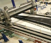
This gantry-style abrasive waterjet system, built by Flow International (Kent, Wash.), machines the Boeing 787 wingbox to final dimensions at Mitsubishi Heavy Industries (Tokyo, Japan). Such large, complex composite structures are more common today, and place greater demands on machining operations. (Image proprietary to and courtesy of Mitsubishi Heavy Industries.) Source: Flow International
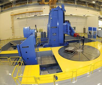
The challenge for the CNC rotary machinery manufacturer is to produce machines that won’t be obsolete, due to changes in cutter technology and customer expectations, before their service life expires. This machining center, built by Ingersoll Machine Tools (Rockford, Ill.), uses a multiaxis machining head that can work composite parts on a turntable. Source: Ingersoll Machine Tools
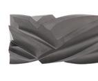
In trimming operations, edge damage can force rejection of the entire part. Compression routers, like this one from AMAMCO Tool (Greer, S.C.), feature opposing flutes, designed to pull composite material from each of the part edges toward the part center in a scissor-like action, which prevents edge fraying and delamination. Source: AMAMCO Tool
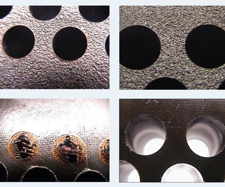
Drilling a clean hole is especially challenging with composites. A worn or dull tool can produce holes with frayed edges and delamination. The photos contrast unacceptable and acceptable entry (top left and right) and unacceptable and acceptable exit holes (bottom left and right). Source: Onsrud Cutter
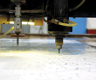
Pegasus Northwest (Kent, Wash.), a supplier of machined composite parts, uses a waterjet system from Jet Edge (St. Michael, Minn.) to drill holes in composite laminates. The holes are first tapped with a rotary tool (right), and then finished with the waterjet (left). The use of waterjet cuts down on dust and airborne contaminants. Source: Pegasus Northwest
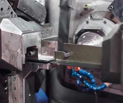
MAG Productivity Solutions’ (Hebron, Ky.) E Mill can perform contour machining, routing, drilling and tapping to produce finished, complex, 3-D parts up to 12m/39.4 ft long in a single setup. In this close-up view, a special end-mill cutter, is being used to produce composite brackets. Source: MAG


There is perhaps no portion of the composites manufacturing process that suffers the variables and uncertainties of carbon fiber-reinforced polymers more than machining.
Not only has the use of carbon fiber composites increased — on projects as diverse as the F-35 Lightning II, the V-22 Osprey, Boeing’s 787 Dreamliner and the Airbus A350 XWB — but the sheer size of composite structures has increased as well. “Five years ago, parts were 10-ft long, maximum, and about one-quarter to one-half inch thick,” says Dan Cooper, CYCLO CUT product manager at MAG Productivity Solutions (Hebron, Ky.). “Today, we’re looking at 60-ft wing skins with thicknesses of 1 to 4 inches. Not since titanium came out 20 years ago have you seen a material have such a large impact on the aerospace industry.”


As the use and size of carbon parts has increased, the dimensional tolerances to which these structures must be produced has tightened dramatically — the margin for error today is so small as to be almost nonexistent. Thus, machining is more critically important than ever.
These are not trivial matters: Machining often is the only means to bring a cured, nearly complete composite structure to its final dimensions. In the aerospace industry, that near-net structure is likely to represent thousands — if not millions — of dollars of engineering expertise, material and manufacturing effort. A flawed machining effort is rarely fixable and, thus, poses a fatal threat to productivity and profitability. “Composites are unforgiving,” says Cooper. “These materials are great at showing weaknesses in your machining process.”
Definitively different materials
To understand why, one must first understand what machining actually does. In the simplest terms, machining is controlled, managed breaking. Historically, aerospace machining was done to monolithic metallic materials — steel, aluminum, titanium, etc. Most metals are formed from crystalline structures. “In metals there are natural lines of fracture and stress,” says Tom Cornwell, applications specialist at cutting tool supplier Onsrud Cutter LP (Libertyville, Ill.). These fracture lines allow the crystalline structures to be “wedged apart by drilling or machining the part.” They tend to break away in more or less uniform chunks and bits when contacted by a machine tool or waterjet and can be easily machined in smaller and smaller increments to achieve the desired dimensions. This predictability, and the fact that humans have been handling, manipulating and accumulating scientific knowledge about metallic materials for hundreds of years, makes machining, drilling and routing metals relatively routine — and it makes metals attractive and relatively easy to manage.
By comparison, composites react very differently and not so predictably. Mark Saberton, chief engineer at waterjet machine manufacturer Flow International Corp. (Kent, Wash.), describes the difference with a similar analogy: “When you machine composites, you don’t peel away material like you do in metal machining.” Here, the layered construction unites a resin matrix with, typically, discrete layers of brittle fiber reinforcement. “You’re really machining fibers, and the proper way to machine them is by fracturing them.”
Because breaking is the intention, there is, of course, the ever-present risk that this violent activity will result in delamination, resulting in part rejection or failure. “Delamination and breakout of composite parts affects the internal structure of the base product, in most cases, and cannot be repaired,” notes Onsrud’s Cornwell.
Composites break less predictably than metals because a greater number of variables dictate how the composite will respond — fiber type, resin type, fiber orientation at the point of contact, composite part thickness, matrix hardness and heat sensitivity, and the type of composite part construction (sandwich vs. solid laminate). Therefore, the composites machinist must take into consideration all of these variables when selecting a machining process and adapting it to the application at hand.
Machining systems 101
There are two basic technologies to choose from: rotary machining and abrasive waterjet machining. Rotary machining employs a cutting tool attached to a high-speed spindle driven by an NC-programmed machining center. The tool has a generally circular but fluted cross-section. The flutes have sharp edges and are typically arranged in a slow spiral configuration, which makes the voids between the flutes a means for the spinning tool to channel broken material away from the work area.
In waterjet machining, a garnet (granular silicate) or similar material is mixed with water and then emitted at very high pressure (60,000 to 100,000 psi). This powerful, abrasive-laden stream, moving at speeds approaching Mach 3 (2,200 mph), is concentrated by a specially designed nozzle into a 0.001-inch/0.254-mm diameter stream that quickly erodes the matrix material and shears the fiber in parts up to 6 inches/152.4 mm thick. It does so without heat generation or dust emission and causes no delamination in the composite, even at a microscopic level. Waterjet systems typically offer 5-axis heads, which enhance manufacturing flexibility and have a built-in probe for measurement work.
Rotary tool or waterjet?
The process selection is based, in part, on the general capabilities and limitations of each technology in terms of three basic machining operations or tasks: trimming, drilling and surface finishing. Rotary cutting tools, depending on how they are designed, can be employed successfully for all three tasks. MAG’s Cooper notes that one of rotary machining’s greatest strengths in the composites sector is surface finishing to bring a part or structure to uniform thickness or to create a tight-tolerance fit between two mating surfaces. Five to six years ago, he says, it was more challenging to mate two surfaces without gaps, each of which required a filler of shims or adhesive. Today, he observes, such gaps are unacceptable, and rotary tooling has responded to allow the precision required for a tight bonded fit.
Abrasive waterjetting, by contrast, has become the de facto standard for many edge-trimming applications, but its essentially linear operation puts some machining tasks, such as countersinking and surface milling, outside the scope of its capabilities. Additionally, cuts that must begin inside the perimeter edge of a part (e.g., for an access door or window), require a mechanically drilled pilot hole. For that reason, waterjet systems must also incorporate a rotary tool head.
Beyond these basic distinctions are many factors that can impact the machinist’s decision-making process. One is heat. Waterjet systems have an inherent advantage here because the water acts both as the propellant for the abrasive and as a coolant. But for rotary machining, heat is an inherent by product. A spindle turning a metallic tool at 20,000 rpm against a highly abrasive surface like carbon fiber will generate a great deal of heat — sometimes more than is healthy for even a cured high-temperature thermoset resin. To combat this, some manufacturers have developed machine tools that feature integrated cooling channels through which compressed air can pass to minimize tool temperature. In other cases, particularly high-volume drilling, direct application of water or another cooling fluid is required. Alternatively, some processors, says Peter Diamantis, general manager at cutting tool supplier AMAMCO Tool (Greer, S.C.), like to drill at higher speeds, subscribing to the notion that heat is minimized if tool time in the hole is minimized. Others, according to Onsrud’s Cornwell, opt for a slower spindle speed to reduce friction. Diamantis offers general speed guidelines: 8,000 rpm for drilling and 5,000 rpm to a maximum of 25,000 rpm for routing. But he warns that exact figures depend very much on the material type, the tooling material and the application. Machinists also can opt for “pecking,” Cornwell adds, where a drill tool intermittently bores into the part and then backs off for cooling. Although these dry techniques compromise production speed, they maintain the quality of the cut, which is paramount.
Another decision point is speed. Waterjetting has gained traction in the trimming environment because it tends to be faster and simpler. One reason is that rotary trimming frequently requires two passes: The first is done with a roughing tool that cuts the edge to near-net shape, removing a lot of material but leaving the cut surface less than perfect. On the second pass, a finishing tool cuts the small amount of material that remains and is designed to produce the smooth finished edge. Flow International contends that in some applications, an abrasive waterjet can cut at twice a rotary tool’s speed and does not require multiple passes. “If you consider that a rotary tool might require a rough cut and a finish cut,” says Flow’s Saberton, “the speed can reach 3x.” Kurt Burton, associate technical fellow at Boeing Integrated Defense Systems (St. Louis, Mo.), reports that waterjet systems have “become a trim standard for most of Boeing.” Recalling one of Boeing’s first uses of a waterjet, on a composite/titanium stack part for the F-18 more than 20 years ago, Burton notes that the original trim work, using rotary machining, required two technicians, eight setups and eight hours. Conversion to a waterjet reduced those requirements to one technician, one setup and one hour.
Cutting tool considerations
Because rotary machining is ubiquitous, even in waterjet operations, there is much concern about, and innovation in, cutting tool technology. MAG’s Cooper speaks for all when he recommends careful study of tool materials and geometry and close management of tool life. Tool material type and geometry, taken together, determine the quality of the “break” and the durability of the tool.
Tool materials for machining composites vary significantly, depending on the application (trimming, drilling or surface finishing) and whether it is a roughing tool or a finishing tool. The baseline tool material is carbide, followed by coated carbide. For high-performance, highly abrasive applications, many suppliers offer diamond-coated CVD (chemical vapor deposition) tools, and tools with a polycrystalline diamond (PCD) coating, a diamond-like coating (DLC), a diamond film coating (DFC), a zirconium nitride coating (ZNC) or a crystalline diamond coating (CDC). The coating choice depends on the application. A part trim might be roughed with a carbide tool and then finished with a coated tool.
A high-hardness coating adds cost — a single-coated tool can cost $600 or more. If a PCD tool’s cost is three times that of a CVD tool, but it trims a composite length four times longer, the economics could favor PCD. On the other hand, a part that has a low-fiber volume fraction, for example, could cut easily to permit the use of a less-aggressive and less-expensive tooling material.
Alex Harding, operations manager at cutting tool supplier Cajero Ltd. (Isle of Sheppey, Kent, U.K.), says the selection of a coating type is critical and must be done carefully. “While the merits of CVD drills exist, the technology and its application are not the panacea,” he says. “Other tool materials can offer distinct advantages when lifecycle costs are considered. For example, reservicing of PCD drills can provide greater product longevity, so that over the life of a project the tool costs are significantly lower.”
In any case, suggests Cornwell, tooling cost is relative. When machining a valuable composite structure worth hundreds of thousands of dollars, whether you spend $200 or $600 per tool might not matter: “Most tools are a fraction of the cost of the part, so sometimes you have to play it safe.”
Tool geometry options are even greater than coating options. “Composites are extremely abrasive, and whether drilling or machining, you need a completely different set of geometries in your tooling to be successful,” says AMAMCO’s Diamantis.
To avoid the risk of delamination, Cooper recommends careful study of the geometry of a tool’s angle of approach. The number of flutes and the angle of flute twist can be, and often are, customized to fit the application. One result of such a study in edge-trimming applications is the compression router. Available from AMAMCO, Onsrud and others, this tool type features opposed sets of flutes that simultaneously “pull” composite material from the top and bottom of the laminate in a scissor fashion (see the photo of a compression router, at right). This minimizes the risk of delamination and produces a clean edge on both the top and bottom surfaces, with few stray fibers along the part edge.
Geometry is particularly important in drilling. Common solutions involve gradients in diameter and/or diameter staging. The former describes a drill tool with a shaft that increases in diameter from entry point to midpoint. The tool thus drills a small pilot hole then gradually reams that hole to the specified size. Staged tools have diameters that change abruptly along their length at planned intervals, simultaneously creating, for example, a pilot hole for the screw in the receiver substrate, a larger hole in the covering substrate and a countersink at the surface. This three-in-one approach is often coupled with stack drilling. Stacking eliminates potential inaccuracies when two parts that must be joined are drilled separately: The parts are drilled after they are fitted together.
Although this technique is efficient and guarantees hole alignment, it can be problematic in composite-to-metal joints. “When you stack metal alloys like aluminum and titanium with composites,” AMAMCO’s Diamantis points out, “you have to produce a tool that somehow addresses both unique attributes at the same time.” Typically, the user must settle for a tool material that is ideal for one substrate but not for the other. This can negatively impact tool life and hole precision. Alternatively, the user can elect to use the optimum drill tool for each material. On the F-35, for example, Lockheed Martin (Ft. Worth, Texas) uses several drill tools of different composition to bore clean holes through stacked composite aircraft skins and the plane’s titanium or aluminum frame members. The extra drilling time is an acceptable trade-off for extended tool life and reduced risk of damage to the composite.
But even when the resin and fiber composition and thickness of the composite structure are known, Cajero’s Harding warns that there is always some uncertainty about the best tool material and geometry. Until a tool is put to a practical test, uncertainty remains. Joe Smith, marketing communications specialist at machining firm Paragon D & E (Grand Rapids, Mich.), goes so far as to suggest that consistency of composites materials is a myth that must be dispelled: “One of the largest misunderstandings that Paragon has seen is in part data,” says Smith. “Many people believe that two composite parts molded from the same mold should have the same data. Paragon has found that this is rarely the case.”
“You can’t go in believing that you have a tool that will meet all needs,” concludes Harding. “You must do trial and error.” This reality is behind the emphasis among tool suppliers on customization. Harding and others work closely with customers to design and test tools for specific applications.
Management of tool life is critical because when machining composites, a tool must be replaced well before it fails, despite its high cost. As tools wear, machining progress slows dramatically and the cut quality declines. The overall cost of operating machinery and a cutting facility (labor and power cost, etc.) must be balanced against what might be, by comparison, the relatively small cost of the individual tool. Replacing it well before failure maintains a clean cut and keeps production speed within acceptable parameters, minimizing cost. Thus, knowing and monitoring wear rate is paramount. At Lockheed Martin, for example, the router for F-35 wingskins cuts about 65 ft/19.8m and is replaced on a regular schedule.
The management of tool life has a parallel in the abrasive waterjetting world. Just as the garnet abrasive erodes the part material, it also wears away the exceedingly hard alloy that forms the surface on the inside diameter of the waterjet nozzle. Just as tool wear degrades edge quality, so does nozzle wear. Nozzles, according to Boeing’s Burton, last at least 40 hours and are on regular wear schedules like rotary tools. Here, however, the waterjet has one advantage over the rotary tool. Unlike the latter, the waterjet nozzle makes no contact with the composites substrate. As a result, nozzle erosion is easier to predict because the factors that impinge on wear are confined to known variables: the garnet, the water pressure and the nozzle material.
Lots and lots of holes
In terms of sheer volume, particularly in aerospace structures, drilling is the most frequent application of machining, and it is the most challenging.
The first and foremost challenge is to maintain dimensional accuracy. In rotary machining, more often than not, this requires a two- or three-tool approach. The first drills a pilot hole to establish the hole position. It is followed by a larger drill/reamer tool to bring the hole to its final dimensions. Sometimes, when tolerance requirements are extremely sensitive, reaming becomes a separate, third step. Waterjet machinists employ a similar strategy. Ron Palstring, general manager at Pegasus Northwest Inc. (Kent, Wash.), says the tolerance for hole accuracy, which once was ±0.010 inch, is now a much tighter ±0.0015 inch. Pegasus, for its part, predrills its holes via rotary tool to establish their positions and then uses one of its five Jet Edge Inc. (St. Michael, Minn.) waterjet systems to finish the job. A spindle/tool set integrated into the work head, at a fixed distance from the waterjet nozzle, sinks the pilot holes. Then the CNC head, adjusting for the tool-to-nozzle offset, retraces its path with the waterjet.
The second challenge is to produce a clean hole, with no delamination or frayed fiber at the exit hole. This task depends on the sharpness of the tool and the speed of drilling. One of the best ways to gauge tool age (sharpness) is to measure the resistance the drill motor encounters as holes are drilled. As the tool wears and dulls, resistance increases; with trial and error testing, the user can determine ahead of time the resistance level that dictates tool change. Although resistance can be checked manually, some machinists have developed systems that monitor the drill’s motor torque and generates an alarm when the torque level is out of spec.
The third challenge is to prevent part contamination or damage from dust and debris. On a rotary drill tool, the cutting spiraling channel cut material out of the hole. But removal of dust and debris from the work surface requires ancillary ventilation and vacuum equipment. By contrast, the waterjet wets the work piece as it cuts, and it drives dust and debris through the hole into the water/abrasive collection system where debris and garnet are extracted and discarded and the water is recycled.
The future: Both less & more
Although the tool suppliers contacted for this article believe that the machining story will continue to be dominated by the ongoing evolution of their rotary tool technologies, Patrick Flesch, director of applications at Ingersoll Machine Tools Inc. (Rockford, Ill.), says that CNC machine manufacturers face the no-less significant task of developing machining center technology that can adapt as those tooling designs change. CNC machinery, he explains, is expected to last 10 to 15 years, but because the tools evolve much more quickly, “we need to provide flexibility in spindle design, spindle speed and CNC capabilities.” Flesch adds that many customers opt to buy more speed than they need to ensure they can meet future needs.
Demand also is on the rise, he notes, for machining systems with auxiliary capabilities. One area of need is laser inspection and laser-based location tools. In countersinking operations, for example, laser-based systems can measure the countersink depth to ensure that fixtures or fastener heads will be flush with the part surface. Ingersoll also has developed what it calls a “pressure foot,” an enclosure around the spindle and tool that presses against and stabilizes the composite structure and then extends the drilling tool a preset distance.
Ultimately, says Flesch there will be great demand for dimensional accuracy on the front end of composites manufacturing (using fiber placement, for example) to ensure that cured composite parts are at, or much nearer to, specified final dimensions right out of the mold. “Everybody wants to drive the machine tool out of the process,” Flesch suggests. But until then, postmold drilling, trimming and surfacing strategies, and the rotary tool and abrasive waterjet equipment and necessary to implement them, will command significant attention among composites manufacturers.


.jpg;maxWidth=300;quality=90;format=webp)
Related Content

Novel dry tape for liquid molded composites
MTorres seeks to enable next-gen aircraft and open new markets for composites with low-cost, high-permeability tapes and versatile, high-speed production lines.
Read More
Cryo-compressed hydrogen, the best solution for storage and refueling stations?
Cryomotive’s CRYOGAS solution claims the highest storage density, lowest refueling cost and widest operating range without H2 losses while using one-fifth the carbon fiber required in compressed gas tanks.
Read More
Price, performance, protection: EV battery enclosures, Part 1
Composite technologies are growing in use as suppliers continue efforts to meet more demanding requirements for EV battery enclosures.
Read More
Recycling end-of-life composite parts: New methods, markets
From infrastructure solutions to consumer products, Polish recycler Anmet and Netherlands-based researchers are developing new methods for repurposing wind turbine blades and other composite parts.
Read MoreRead Next

Composites end markets: Energy (2024)
Composites are used widely in oil/gas, wind and other renewable energy applications. Despite market challenges, growth potential and innovation for composites continue.
Read More
From the CW Archives: The tale of the thermoplastic cryotank
In 2006, guest columnist Bob Hartunian related the story of his efforts two decades prior, while at McDonnell Douglas, to develop a thermoplastic composite crytank for hydrogen storage. He learned a lot of lessons.
Read More
CW’s 2024 Top Shops survey offers new approach to benchmarking
Respondents that complete the survey by April 30, 2024, have the chance to be recognized as an honoree.
Read More