
Machine vision: Rapid error detection
Aerospace-aimed ply placement technology evolves into process management and near-real time inspection system for production laminated composite parts.

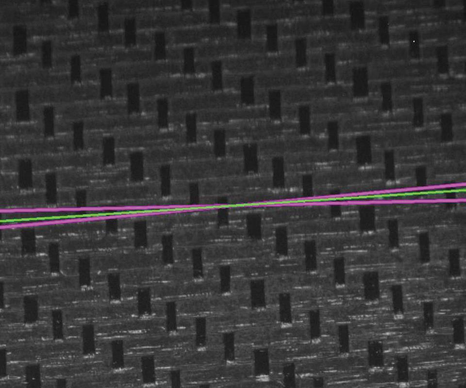
Seeing beyond ply placement. As the Aligned Vision team’s members worked with customers and images, they realized they could see other things besides ply locations, which led them to develop automatic fiber-orientation measurement. The system works by looking for optical signatures. For example, different types of fabrics are recognized by different image-analysis algorithms. In the layup shown above, the measured orientation for the material at this location is shown in green and the two magenta lines represent the orientation tolerance. Source: Aligned Vision
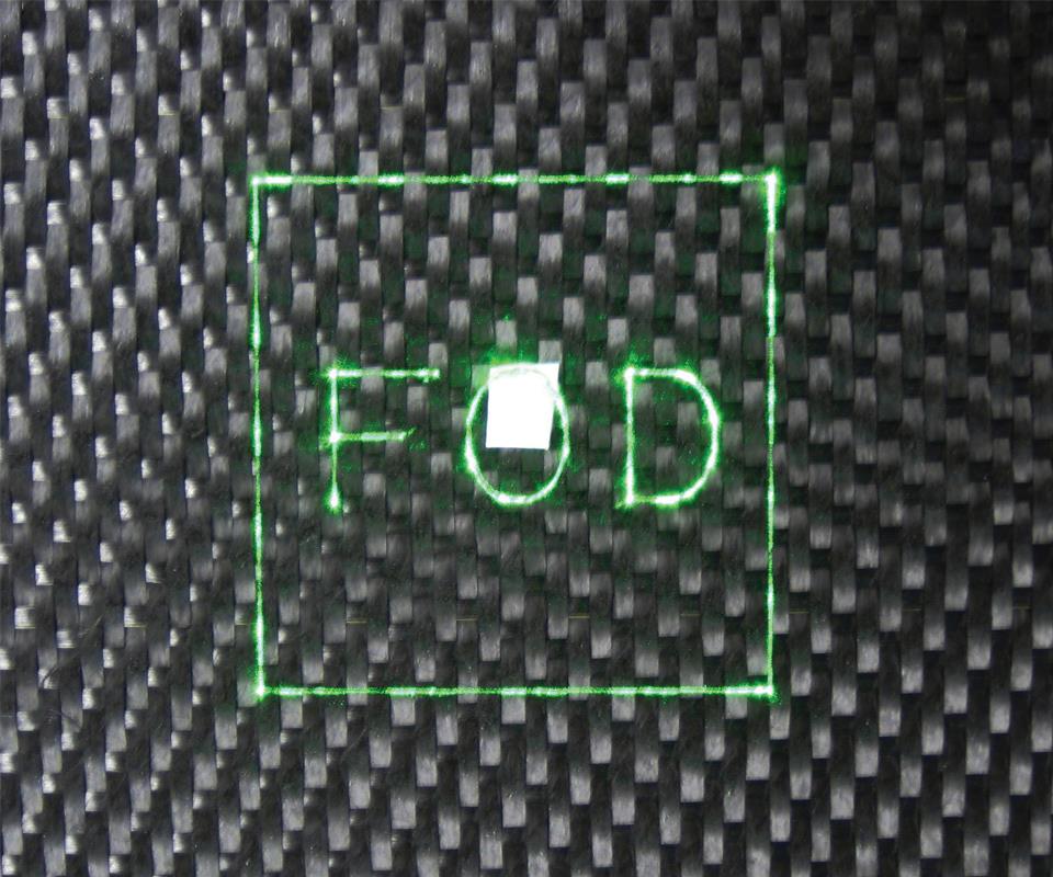
Seeing what doesn’t belong. The system not only looks for what should be in a part but also what should not be there. Aligned Vision’s system can see foreign objects and debris (FOD), which can get between plies and prevent proper interlaminar cure, resulting in loss of strength in that region. By agging FOD during layup, pre-cure, when it’s still easy to remove, the system helps prevent what could lead to expensive rework, scrapping of a part or worse, in-service part failure. Source: Aligned Vision


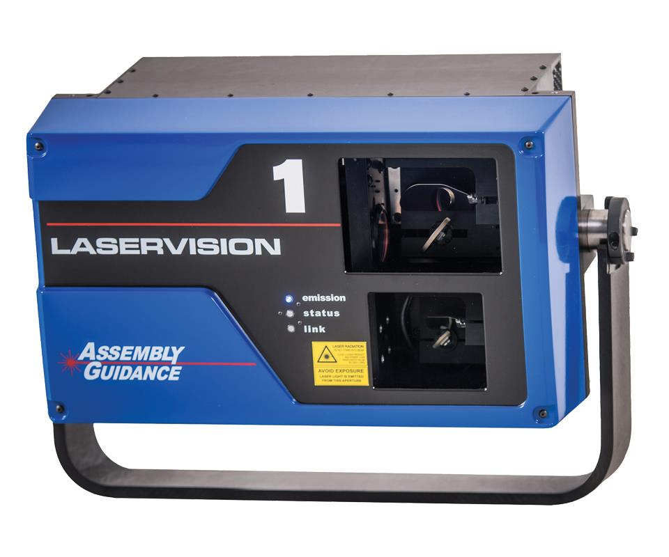
An aerospace technology that combines a camera, a laser-projection system, and special software provides inline inspection and error detection in the layup of laminate composite parts. Offered by Aligned Vision (formerly Assembly Guidance Systems Inc., Chelmsford, MA, US), it is already in use at several aerospace customers. The company hopes that, as the automotive industry ramps up composites production capacity, it also will implement automatic composites inspection at a point where error detection and defect correction are least expensive.
Hide n’ seek
The current technology evolved out of Aligned Vision’s work developing laser-templating systems, which are used for laminate composite kit cutting, layup and inspection. In the 1990s, the company was working for the US Air Force at Wright-Patterson Air Force Base’s Materials Directorate, when someone asked the team if its system’s laser and optical-aiming system (mirrors that aim a dot of laser light) could do more than project a pattern onto a part. Aligned Vision subsequently placed a camera in the optical aiming path of its LASERGUIDE projector to verify and document that design features, such as the edges of plies, were present. In so doing, the company turned a standard laser projector into an output/input device, which it called the LASERGUIDE Process Control System. Fortunately, the optical-aiming system was already tied to and driven by computer-aided design (CAD) data.


As the Aligned Vision team continued working with customers and images, they realized they could “see” much more than ply location. “With image analysis, you can see edges everywhere — thousands of strands of material,” explains Scott Blake, Aligned Vision’s founder and president. “That led us to develop automatic fiber-orientation measurement.” He notes that the system looks for optical signatures. For example, different types of fabrics are recognized by different image-analysis algorithms (i.e., a three-over-one fabric looks different than a balanced weave fabric, and a hybrid fabric of glass and carbon fiber looks different than a fabric that’s all glass or all carbon). Interestingly, the system has even been used to measure “isotropicity.” A research lab used it to verify the randomness of its spray-up work, because the flatter the system’s fiber-orientation plot, the more anisotropic is the fiber orientation.
Data for analyzing the image and evaluating tolerances can be generated via commercial design tools, such as Fibersim, from Siemens PLM Software Inc. (Plano, TX, US), and CATIA Composite Workbench, from Dassault Systèmes (Velizy Villacoublay, France). Different configurations of projection and imaging can automatically detect issues, such as material shear, wrinkles and bridging, and the laser projector automatically pinpoints areas of concern, including locations of foreign objects and debris (FOD).
“FOD is ever-present,” Blake points out. “Everyone has FOD problems and it’s caused by a variety of things, ranging from static cling that causes plastic liner material to stick to plies to something falling out of someone’s pocket. I know of companies who’ve accidentally cured things like rulers, badges, coins and even a cell phone into parts. We aren’t operating in super sterile environments here.” FOD can prevent interlaminar cure and compromise part strength at its location. Automated FOD detection now enables a fast, cheap fix before the next layer’s placement, and certainly before a part is cured and found to be unacceptable — or worse, is used and fails during service.
“The approach we have and the path we’ve been driven down [by our customers] is developing a technology that lets you know that every- thing about a part is right — the right material put down in the right place in the right way — at the lowest cost and in the shortest amount of time. If something isn’t right, the system directs you to take action and make corrections before you’ve got more resources invested,” Blake adds.
The system’s projection and imaging field is a 60° cone that typically operates at a distance of 15 ft/4.6m from the part layup, thereby yielding a 15-ft2/1.4m2 envelope. For complex or large parts, multiple units can either be ganged together or mounted on a gantry and moved. Individual images of small regions within a larger, more complex field are captured in high resolution (4 megapixels) and analyzed to verify the location and presence or absence of specific characteristics (such as FOD).
The LASERVISION system is connected to a fast local-area network (LAN) and a high-end personal computer (the system becomes another node on the network). For automated composites manufacturing processes used in the aerospace industry, companies such as Electroimpact Inc. (Mukilteo, WA, US) typically purchase the system to use as a component in a large manufacturing cell. In these cases, Laservision doesn’t operate as a standalone system. Instead, it is integrated into the workcell’s control and data collection system, enabling it and the workcell’s equipment to work together, seamlessly.
Although the Laservision system has many benefits, it does have a few limitations. Because vision is a surface phenomenon, the flaw must have visible characteristics if it is to be “seen.” For example, the system may find it hard to detect very thin and transparent glass fibers or have trouble assessing if all the plies are in place in a schedule where layups are identical from one layer to the next. Unlike X-ray or ultra-sound inspection systems, it cannot detect flaws hidden deep within a part. For example, it cannot tell the operator if a core is attached to skins in a sandwich-panel composite. Another issue can be the imaging angle: the more “normal” (perpendicular to the surface plane) the angle is to the area of a part being imaged, the better; conversely, the more tangential the angle, the more challenges the system will have reading the area accurately.
And customer willingness to implement new technology also can play a role. “FOD will always be visible at some point in the process. However, a customer who’s not willing to look at the bottom of each ply? Well ....” Blake quips, “that’s where the FOD is going to be.”
The high cost of not knowing
Given the size and cost of parts in the aerospace industry, where Aligned Vision does most of its business currently, the ability to catch critical flaws when they can be most readily remedied is easily cost-justified if, Blake argues, one is looking at the right data. “Complex repairs, scrap, and lengthy material review processes have extensive costs associated with them that are not captured by traditional accounting,” he points out. “When true costs are considered, our system — which is priced between US$100,000 and US$150,000 — quickly pays for itself by preventing a small number of flaws that would otherwise result in scrap or part failure.”
The systems’ value can increase when it becomes a node on a deep-learning network. Used in combination with other process- monitoring sensors and statistical process control (SPC) tools, it can help operators characterize flaws in terms of cause and frequency, and then operators can modify the process on all machines on that network to avoid errors of the same type in the future.
Furthermore, the level of detail provided by this system’s type of automatic documentation can pay dividends at any future point in the part’s service life.
“Twenty years from now, if there’s a problem with a part, your customer will know where every splice and gap is, along with resin and other fiber characteristics in every layer of that component,” Blake posits. “Memory is [virtually] free these days. It’s much better than a distracted human inspector entering a code to indicate that a part meets spec.”
Although it is established in aerospace and defense circles, the company’s system, Blake acknowledges, is so far only used in one auto industry production environment, although Formula 1 racing teams are said to be interested in the system’s ability to verify as-built fiber orientation because it can help them optimize next-generation parts. The carmakers who have looked at the system reportedly love what it can do.
So, will the automotive industry come to value this type of near-real time error detection as well? Few would argue that for composites to have a serious impact in automotive, two things are needed: cost reduction and quality improvements. Says Blake, “For me, quality improvement means building your part and knowing that everything about it is right and at the lowest cost.


.jpg;maxWidth=300;quality=90;format=webp)


Related Content

Evolution of the one-piece, all-composite Funny Car body
Large, one-piece drag racing vehicle bodies require extreme lightweighting and precise layup skills. Specialist MTCcorp shares how its John Force Racing Funny Cars have evolved over the past 25 years.
Read More
Novel processes for hybrid thermoset-thermoplastic pultruded parts
CFRP pultrusion and pullwinding specialist Epsilon Composite combines thermoplastic overmolding with traditional thermoset processes, demonstrated through aircraft struts and industrial applications.
Read More
New polymer expands composites options in demanding environments
Aromatic thermosetting copolyester offers unique properties, availability in multiple form factors.
Read More
Multi-flange RTM frames enable radical rear fuselage design
The Clean Sky 2 Advanced Rear End (ARE) demonstrator combines patented new frame design, thermoset and thermoplastic composites and smart tooling to advance aircraft design and cut weight, cost and production time.
Read MoreRead Next

CW’s 2024 Top Shops survey offers new approach to benchmarking
Respondents that complete the survey by April 30, 2024, have the chance to be recognized as an honoree.
Read More
Composites end markets: Energy (2024)
Composites are used widely in oil/gas, wind and other renewable energy applications. Despite market challenges, growth potential and innovation for composites continue.
Read More
From the CW Archives: The tale of the thermoplastic cryotank
In 2006, guest columnist Bob Hartunian related the story of his efforts two decades prior, while at McDonnell Douglas, to develop a thermoplastic composite crytank for hydrogen storage. He learned a lot of lessons.
Read More