
Laser projection: Envisioning more than templates
Advanced systems offer ply-placement verification, aids to faster assembly and manufacturing process and quality control.

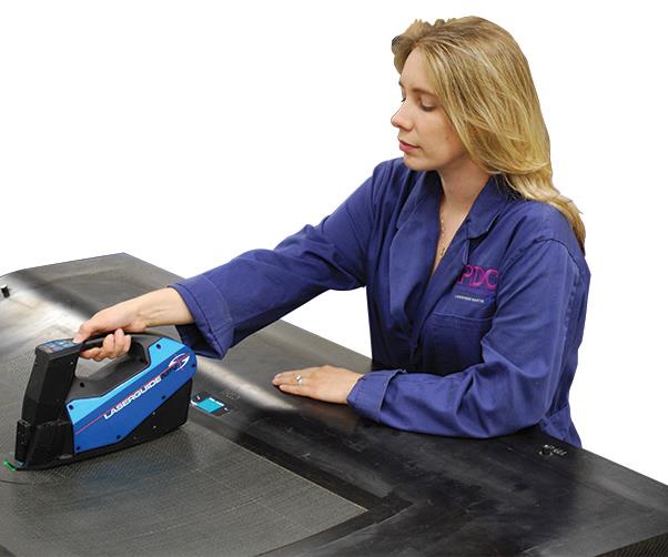
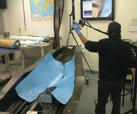
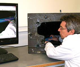
Laser systems are moving beyond layup aids into in-process design verification and process control. Here, a worker uses Assembly Guidance’s handheld instrument, called a HAMPI (High Accuracy Manually Positioned Inspector), part of the company’s Automatic Ply Verification (APV) system. The FAA and US Army consider APV the equivalent of a required second inspector who measures fiber orientation with a calibrated instrument. Source: Assembly Guidance
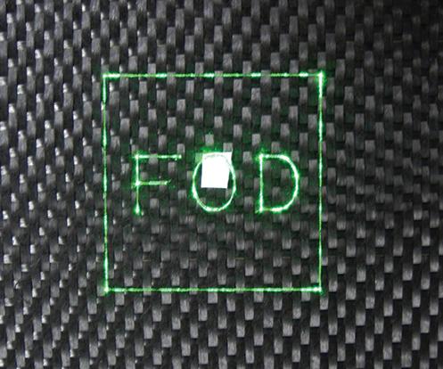
Foreign object detection: Laser projection systems can be equipped with vision systems to help in foreign object detection (FOD). This FOD indication shows the operator of an Assembly Guidance laser system where its Process Control System has detected a problem. The operator cannot proceed unless the problem is resolved or the operator overrides the system. Source: Assembly Guidance
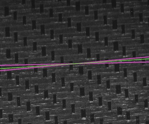
Fiber orientation: Verification & documentation: This closeup shows a 2° tolerance (the purple lines) and the green line indicating the measured fiber orientation in this composite layup, an example of how the laser system can verify and document fiber orientation, even on a ply-by-ply basis. Source: Assembly Guidance
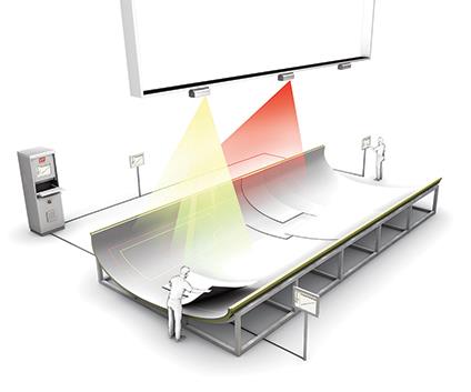
Multi-team/multi-projector control capability: This rendering shows how LAP Optogroup, a concept offered by LAP-Laser, allows several teams or groups to work at different locations on a large object, simultaneously, with shared projection capacity controlled by remote devices. Source: LAP-Laser
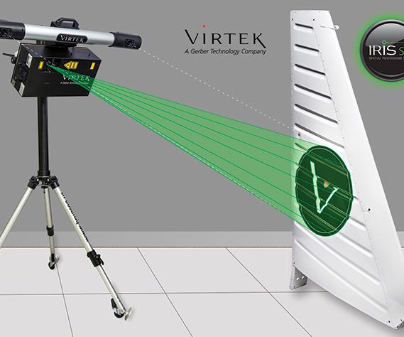
Targetless work area alignment: The new IRIS Spatial Positioning System (SPS), a targetless vision technology from Virtek, pairs a Virtek projector with a vision system, called a “spatial locator.” The locator takes visual measurements of the tool or work area, aligns to predetermined physical datum features on the tool, like surfaces, edges, or holes, and transmits that data to the projector to align the CAD model correctly in 3D space, onto the work area. The system expands laser projection’s capabilities by allowing its use on very large or awkwardly shaped tools, because it can “see” all parts of the work area. Source: Virtek Vision
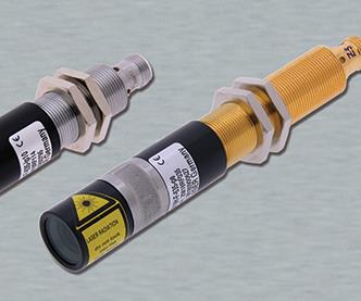
Next-gen green/blue lasers maximize optical output: Z-LASER recently launched the third generation of its ZM18 machine vision lasers. The ZM18S3 (left) increases modulation frequency (TTL) from 1 kHz to 500 kHz, while the ZM18H3 (right) is a power-stabilized laser with green or blue wavelength. The third-generation lasers also increase maximum optical output to 200 mW. Source: Z-LASER
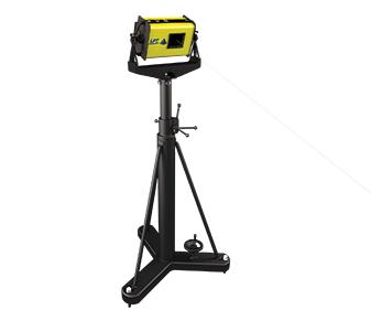
Laser projector portability: An example of a projector mounted on a stand, which can be easily moved as tools are changed in the layup area. Source: LPT Corp.
Capturing the action on camera: PlyMatch from Anaglyph is not a laser projection system, but works by filming the work area and mold with a video camera, and blending that live image with the ply software image, generated by CAD or design file, on a monitor. Source: Anaglyph
Placement in hard-to-reach places: Using PlyMatch from Anaglyph, the operator watches the monitor as the ply is placed, matching the software-imposed outline, and the camera documents each step. It is reportedly ideal for deep or cavity molds, as shown here. Source: Anaglyph


Of the thousands of beneficial composites processing innovations developed over the past decades, laser projection systems rank near the top. Introduced in the 1990s, they replaced physical cumbersome templates as customer demand for shorter production cycles became more aggressive, significantly reducing labor, time and part scrap during layup. More recently, however, laser projection systems originally purchased to speed ply placement, in some settings, are finding application beyond manual ply placement/verification. Suppliers and their customers are adapting them to perform process and quality control and expanding the scope of their effectiveness, taking advantage of their already established links to the part’s CAD design software.
“Laser projection is changing,” says Scott Blake, president of Assembly Guidance Systems Inc. (Chelmsford, MA, US). “It is starting to be used to determine if parts are being built as designed, using the fewest resources, not only for hand layup but in automated work environments.”


“Automated layup is the way of the future,” agrees Sean Francoz, senior product manager at Virtek Vision International Inc. (Waterloo, ON, Canada, a subsidiary of Gerber Technology, Tolland, CT, US). But he’s careful to point out that laser projection’s root application will remain the same: “Manual layup isn’t going to go away,” he asserts. “There will always be manual assembly steps on aircraft, for instance.”
Laser projection: Systems & software
The key to understanding where laser projection is going is found in how it works. In a nutshell (for more, see “Learn More,” p. 57), a projector mounted above the work area produces a light beam from a low-level laser source. Using a system of mirrors and galvanometers controlled by a computer, it converts the laser’s stationary dot of light into a “traveling” sequence of points that refreshes so quickly that it can create what appears to the human eye to be persistent, accurate ply outlines — a glowing virtual template. Historically, retroreflective alignment pins or targets positioned at the edges of the tool (retroreflectors direct light back to the source with minimal scatter) have acted as reference points, enabling the system to accurately establish the tool within three-dimensional space. Some newer systems, as we’ll see, no longer require reflector targets. Using the part’s CAD file information, the projector’s computerized system projects onto the tool the exact boundaries of successive prepreg plies. As the technician places each ply, he or she confirms each step on the computer screen as layup advances. Although first-generation systems used heavy hot-gas lasers, advancements have resulted in smaller, more compact units with diodes that project cool green light with less flickering, at safe laser levels.
Those who use projectors must have a way to access the part’s CAD ply design information. They have several options. Some CAD software packages include laser projection modules — Dassault Systèmes CATIA (Waltham, MA, US) has a generic module within its Composites Product Design (CPD) package. The Fibersim composite engineering suite from Siemens PLM Software Inc. (Waltham, MA, US) offers a laser projection interface that generates and verifies data consumed by laser controller software solutions. Fibersim, given its open architecture, can generate data from the ply boundaries in its CAD composite engineering solution for all laser systems, says Leigh Hudson, Fibersim product manager at Siemens. In addition, the Fibersim laser projection interface generates data consumed by laser verification systems, such as the Automated Ply Verification (APV) solution from Assembly Guidance (noted below), that validate that a ply has been properly placed on the tool. “It is very important to ensure the ‘as-manufactured’ and ‘as-designed’ product is the same,” says Hudson.
Several third-party interface options also facilitate laser projection with software solutions. One is metrology specialist Verisurf Software Inc.(Anaheim, CA, US). Built on the company’s CAD/CAM system, Verisurf Laser Projection enables users to create laser projection programs from any supplier’s native CAD file format, including SolidWorks, SolidEdge, AutoCAD, CATIA and more. It enables live “pick-and-shoot” programming, for selection and instant projection of ply geometry. Verisurf Laser Projection software is reportedly compatible with laser projectors from all suppliers. Magestic Systems Inc. (Westwood, NJ, US, now owned by Autodesk Inc., San Rafael, CA, US) began development in the mid-1990s of add-on software that integrates the laser projection system’s software control system with the exact ply-by-ply CAD data, regardless of the CAD system used. The company’s TruLASER software enables a more accurate layup, says the company, because it adjusts the projected laser line to avoid parallax error as the layup increases in thickness on the tool.
From ply placement to design verification
With its many benefits, laser projection has some limitations. Cost is one. For very simple parts, tens of thousands of dollars for a laser projector doesn’t make sense when a low-cost physical template fits the bill. Says Blake, “Our applications can significantly improve cycle time for very complex layups that take dozens to hundreds of plies.” Another issue is deep draw or very complex, curved molds, such as flap track fairings. A laser also can have difficulty holding tolerances on steep vertical surfaces and cannot project a ply boundary on a surface obstructed by an overhang. In some cases, multiple projectors can do the job. But such realities pose a challenge. “Design is too often isolated from manufacturing,” Blake points out. “The design process has to make it to the shop floor.” For that reason, Assembly Guidance took a role in pushing laser placement into in-process design verification, or process control, as early as the mid-1990s, and it was the impetus for the development of his company’s APV System.
“We won an SBIR [Small Business Innovation Research] grant and developed a system while working with Sikorsky on layup of helicopter blades,” Blake notes. The OEM wanted to be able to verify with great accuracy exactly how each blade had been produced, down to precise fiber angles for each ply. Blake’s group developed a projector combined with a camera, with the camera images referenced to the CAD design model. Blake says the system was so successful that the US Federal Aviation Admin. (FAA) and the US Army ultimately accepted it as a substitute for one of two required human inspectors who manually verify fiber orientation of composite plies for flight-critical parts using a calibrated instrument. (One supplier has adapted a camera-based system for ply-placement duty. See “Camera-based ply placement,” at the end of this article or click on its title under "Editor's Picks" at top right.)
The current version of APV involves Assembly Guidance’s Laserguide laser projection system combined with a handheld instrument called a HAMPI (High Accuracy Manually Positioned Inspector) — the latter for key parts on which critical fiber orientations must be verified, documented and traced. The Laserguide software tells the operator where to place the HAMPI device; HAMPI then illuminates, captures, calibrates and analyzes a digital image of the region. The APV system, using the image, can verify material type, ply presence and sequence, correct location and orientation. The system won’t allow the operator to proceed to the next layup until the inspection results fall within manufacturing tolerances, and all data is archived in a report format to ensure comprehensive traceability. “Even after the part is cured, there is a quantitative, physical record of what is inside,” says Blake. “Quality departments love this because they don’t have to be present at the tool to buy off on each ply, and layup operators love it because they don’t have to stand around waiting for inspectors,” he quips.
He adds that APV has been through a rigorous failure analysis with the US Army. The system reportedly can verify and document fiber orientation tolerances of 2º, with a certified accuracy and resolution of 1º, based on required customer certification procedures. Blake recalls that he has seen distracted or fatigued shop technicians refuse to believe that a mistake has been made: “They’ll say that the APV system is broken!”
To prevent debris from turning a part into scrap, APV includes foreign object detection (FOD) capability that halts the manufacturing process until the object is removed, and projects an outline around FOD on the mold surface (see photo, at left).
“We’re finding that manufacturers are being required to maximize the information content delivered with each part. They want to know that ply orientation for the part was correctly manufactured, and that information documented and traceable, even to material batch for each ply or the vacuum gauge used in each debulk,” says Blake. In response, an enhanced version of Laserguide, called Laserguide ProjectorVision, records signals directly from each layup operator’s remote control as it is used for data collection, including scanning barcodes, entering data (i.e., mold release application) and system control functions, and securely saves the information even in the event of a power failure. More importantly, says Blake, the system reduces uncertainty in the composites design/build process, because the designer has confirmation that the part has been built as designed. Assembly Guidance is working with several composite design software providers, including Siemens, to develop more optimized design tools for aerospace composites.
A more complete composites toolbox
“Manual ply layup is important in manufacturing processes,” says Karsten Hofmann, co-owner and innovation manager at LAP Laser LLC(Erlanger, KY, US, and Lüneburg, Germany), “but today’s composites manufacturing technology is becoming as automated as possible, for example, in automated tape laying or compression molding.” Hofmann adds that even when the majority of composite plies are placed by machine, many shops can still benefit from a laser assembly-guide system, for quality assurance and to support efficient production processes.
LAP Laser’s Composite PRO laser projection system is already recognized as compact and lightweight. It also offers outlines in different colors, for easier display of ply groups, and its Viewport feature selects and highlights certain complex areas for better visibility. “Load balancing,” adds Hofmann, “distributes projection data by mold area and part complexity, rather than by projector position, so that the greatest illumination power is focused on the area requiring the most attention.” Further, LAP Optogroup, a client-server concept, enables several teams or groups to work at different locations on a large object, simultaneously, with shared projection capacity controlled by remote devices (see top photo, at left).
He points out that the LAP Laser projection system organizes the workflow on the shop floor: “It creates a structural work order, a systemic list of tasks, which really helps a company technician to go beyond the physical ply layup.” In Hofmann’s view, this kind of organized system can help speed the part manufacturing process. While LAP Laser receives customer requests for the automated quality control and verification functions described above, he believes there’s still a long way to go in that area, and says LAP Laser continues to research new QC technology. Hofmann offers a “pragmatic” solution, where the Composite PRO system directs the technician, who then verifies that the plies are located within tolerances, noting that this still improves productivity at a lower cost.
“We’ve still got a long way to go in the aerospace industry in terms of improving production speed,” says Hofmann, pointing out that “laser systems can play a big role in hastening aircraft assembly, hole drilling, bracket placement and so much more.”
Jason Galek, president of SL-Laser Systems LLC (Charlotte, NC, US, the North American arm of SL-Laser Systems LP (Traunreut, Germany) describes his company’s products as ranging from the small and compact ProDirector XS2 for confined spaces (e.g., an aircraft interior) to the larger format ProDirector 6 for workcell and “harsh” industrial environments. But he adds, “SL-Laser is as much a software company as we are a hardware company. Our SL3D software suite is open and adaptable for customer integration, additional hardware, such as coordinate measuring devices, or third party software.”
SL-Laser’s software reportedly includes a unique, integrated “CAD engine” that takes data from any CAD package, even the most basic, to enable smaller composites shops to use laser projection. Explains Galek, “A small shop may not have the budget or engineering training to deploy an integrated design software program, and this enables them to employ the laser device in their operations.” That said, SL-Laser has partnerships with several large industry software providers as well. The company introduced software and hardware at JEC Europe 2015 to assist fabricators in 3D structural assembly applications, particularly for the ground transportation sector, including trains, trucks, buses, cars and heavy equipment.
The company’s calibration method reportedly provides better linearization resolution (that is, sharpness of the projected ply boundaries) than other laser projectors, claims Galek. “This allows us to hold tighter tolerances on steep, vertical tool surfaces in deep-cavity tools and shows fine detail on tight-radius curves.”
If a company requests it, SL-Laser also can incorporate inspection “brakes,” that stop the layup process until a supervisor has verified that layup can proceed. Other available tools include barcoding and ply placement recording, with cameras and production data logging. “As shorter cycle times increasingly dominate the conversation in composites production, we want to incorporate quality improvements that can be seamlessly integrated in parallel with the process rather than contributing to added production time,” he asserts.
Freiburg, Germany-based Z-LASER Optoelektronik GmbH offers its LP-HFD laser projectors, with flicker-free beam and durable performance, in a wide choice of output power, from 7 mW to 40 mW, in red or green output, says sales manager Dr. Roland Fritz. CW previously documented the Advanced Manufacturing Innovation Initiative (see “Learn More”), during which multiple Z-Laser projectors were ganged together above wind turbine blade molds in a production scenario. Precise projections of plies, core, shear web and adhesives placements helped reduce blade cycle time by 37%.
Z-Laser has contributed to automotive projects as well, and has provided projectors to guide workers through each step of automotive interior equipment assembly (e.g., car doors). Because Z-Laser can display instruction text and point out FOD or other problem areas, worker training time can be reduced while simultaneously improving quality control.
At the recent JEC Europe 2015 event, Z-Laser introduced its Z3D-Control system, which combines laser projection and a stereo camera system, says Fritz. Intended for large parts or objects with a great depth of focus, the system has FOD capability, and projects the defective area’s location directly onto the workpiece. “Vastly increased efficiency and cost reduction can be achieved in assembly of large parts by combining 3D object data acquisition, variance analysis and laser-based assembly guidance,” says Fritz.
Beyond laser to radar
Steve Kaufman, president, Laser Projection Technologies (LPT, Londonderry, NH, US), confirms the trend: “We’re definitely seeing a shift. Customers now want in-process verification — to know that manufacturing is proceeding according to plan.” LPT offers several levels of systems capable of process control and verification, including FOD and 3D measurement in real time.
Kaufman cites a phenomenon he calls “tribal knowledge:” Workers on the shop floor receive CAD designs and lay up parts; if something isn’t quite right, they “fix” it — adjusting or trimming a ply, for example — typically without providing feedback to engineering. He points out that if that skilled technician isn’t around to make that fix, and tribal knowledge breaks down, the part isn’t going to be right.
“Our LPT15 system uses two projector units, working together, to provide high-speed, noncontact measurement technology that allows the company to validate what’s being built.” And, it does this without photogrammetric targets, he adds. Guided by LPT’s RayTracer software code, the LPT15 system scans features of a part, tool or assembly such as drilled holes, corners, edges or tooling balls, using LPT-patented technology devices called PMTs (Photo Multiplier Tubes) for laser signal feedback. A PMT, explains Kaufman, is an extremely sensitive light-detecting system — much more sensitive than typical photo detectors used with standard laser projectors: “These PMT light detectors allow the scanning projector to detect enough laser energy reflected from tool or work surfaces to create an image from the scan.” The scanning laser projectors emit and steer a visible green laser beam (<5 mW) across features in a raster scan array. The PMTs reportedly can sense 100 million times less light energy than the scanning projector sends out, enabling it to detect the key features.
Working with the CAD data file, the projectors scan the projected laser “spots” to determine their location in 3D space with respect to the tool. The LPT15 can detect and measure the angles of composite plies during the layup process, and verify that parts and assemblies are being manufactured within the process tolerances. In addition, the system can scan parts, tools and work areas for foreign objects during the process and stop the process until the object is removed.
Kaufman dislikes camera technology for in-process verification: “The problems with cameras are numerous, least of which is the inherent poor granularity, instabilities and the inaccuracy of the chips. They should only be used in a bundling setup, where multiple pictures are taken from multiple angles, using coded photogrammetric targets stuck to the surface of the object.” That’s why the LPT15 uses the paired lasers, a process Kaufman calls “lasergrammetry.”
LPT’s latest product offering is the LPT100. It uses a similar detection system as the LPT12 and LPT15, but adds a high-resolution, extremely high-speed, “time of flight” LIDAR (light detection and ranging) noncontact measurement system. In high-accuracy measurement mode (0.125 mm, full field) this system can deliver 4,000-5,000 measured points on a 3D object (e.g., a part in a tool) per second, asserts Kaufman. Those points form a “point cloud” that is compared to the CAD model to identify the sections of the object that are out of tolerance. The LPT100 then projects a high-speed, glowing image directly onto the surface where discrepancies are located, to facilitate in-process fixes.
Moving targets
“The current state of the art is human inspectors,” says Virtek Vision’s Francoz. “Highlighting ply boundaries on the part speeds that inspection. Yet, there’s a balance between maintaining adequate inspection for quality control and maintaining fast cycle times.”
Virtek’s trademarked LaserEdge laser templating system is used to guide operators in many industries, including composites, and has features that maximize productivity, asserts Francoz. Multi-Task enables one LPS 7H projector to serve multiple workstations, so that ply layup can occur on multiple parts, in parallel, or multiple projectors can be networked. The system’s application programming interface (API) uses a standard web service that integrates external devices or automated equipment that might include CNC-based flatbed cutting systems, automated layup, barcode readers and/or other manufacturing execution solutions. “Our system projects recognizable icons directly onto the work surface and minimizes the need to go back and forth between the tool and the computer workstation, and it eliminates the need for remote control units,” he explains.
The newest addition to Virtek’s product offerings is its trademarked IRIS Spatial Positioning System (SPS), a targetless vision technology. The system pairs a Virtek projector with a vision system, called a “spatial locator.” The locator takes visual measurements of the tool or work area, aligns to pre-selected physical datum features on the tool, such as surfaces, edges or holes, and transmits that data to the projector to align the CAD model correctly in 3D space, onto the work area.
The system expands laser projection’s capabilities by allowing its use on very large or awkwardly shaped tools, because it can “see” all parts of the work area, something not possible with older-style reflective targets. IRIS periodically checks for the position of the part relative to the spatial locator, and any changes in the position of the projector or tool are updated and realigned in the projection system to ensure projected line accuracy for placement of plies or elements on the work surface. An intuitive, user-friendly operator interface speeds workflow, and a remote controller reduces trips back to the computer screen.
A Virtek LaserEdge system was recently installed by Fives Cincinnati(Hebron, KY, US) for use with its Viper automated fiber placement (AFP) machine, one of several used to lay up very large carbon composite parts at an aerospace manufacturing facility, says Fives Cincinnati technical sales director Robert Harper. Virtek laser projectors are mounted above the Viper machine, making them independent of the AFP’s movements, a key point for accurate projection.
“The Virtek projector’s control system and the Viper’s machine control system work hand in hand,” explains Harper. “The Viper sends a signal to the laser unit, telling it it’s done with that ply, and a human inspector verifies that the ply is correctly placed in relation to the projected image.” The operator must “accept” the ply on the Virtek control system for the projector to advance to the next ply boundary image, and the Viper begins the next sequence. “It is being employed as a manufacturing aid, for faster part production, but is not a ‘vision’ system for process control.”
Because of the part’s large size and round shape, numerous projection targets are needed. Fives Cincinnati worked with Virtek to create magnetic reflective targets that fit down into holes in the tool. Held in place with bushings, the sealed targets are placed as needed to define the fiber placement work area, and to track the long Viper machine movements during layup. The targets are removed before part cure.
Harper stresses that Fives Cincinnati works with all of the laser projection system suppliers and is brand-agnostic. The aerospace project was “an end-user preference,” he asserts. He also notes that any of Fives Cincinnati machines could be adapted to work with a laser projection system. CW has spoken with other automated composites processing machine suppliers who are adopting laser projection, as well. One willing to speak about applications this early was MTorres(Torres de Elorz, Navarra, Spain), which is incorporating laser projection on its automated tape-laying machines used in Airbus A350 XWB production, to enable “on-the-fly” inspection of tape position as tapes are applied to the tool. The company says the laser inspection saves significant time in on-machine inspection.
Bringing part cost down
In the end, laser projection is one of many tools for the composites industry for making better parts, faster. “It’s all about optimization of design,” concludes Blake.
Virtek’s Francoz sums up, “The trend we see is the use of laser projection to lower the total cost of composite part ownership, that is, making production, whether manual or automated, more efficient with less down time.” Adds SL-Laser’s Galek, “We’re living the future now. There have been huge leaps in laser component technologies, and even after a quarter century, we still talk to companies with new applications ... we’re adapting this technology to new industry needs.”


.jpg;maxWidth=300;quality=90;format=webp)


Related Content

From the CW Archives: Airbus A400M cargo door
The inaugural CW From the Archives revisits Sara Black’s 2007 story on out-of-autoclave infusion used to fabricate the massive composite upper cargo door for the Airbus A400M military airlifter.
Read More
Composite resins price change report
CW’s running summary of resin price change announcements from major material suppliers that serve the composites manufacturing industry.
Read More
Materials & Processes: Fabrication methods
There are numerous methods for fabricating composite components. Selection of a method for a particular part, therefore, will depend on the materials, the part design and end-use or application. Here's a guide to selection.
Read More
Materials & Processes: Fibers for composites
The structural properties of composite materials are derived primarily from the fiber reinforcement. Fiber types, their manufacture, their uses and the end-market applications in which they find most use are described.
Read MoreRead Next

Laser projection systems improve composite ply placement
Lighter, more intelligent and increasingly versatile laser systems light the way to accurate and efficient ply placement.
Read More
Blade cycle time: 37 percent faster
Ongoing private/public effort to optimize blade manufacturing targets current production and anticipates “next-generation” offshore applications.
Read More
Blade cycle time: 37 percent faster
Ongoing private/public effort to optimize blade manufacturing targets current production and anticipates “next-generation” offshore applications.
Read More