
Increasing the industrial adoption of composites additive manufacturing
The additive manufacturing industry has challenged the design community to develop an efficient product engineering platform where the barriers between design, optimization and simulation would be broken and optimized parts could be explored in the design environment.

Rani Richardson is a CATIA composites and additive manufacturing consultant at Dassault Systèmes (Waltham, MA, US), responsible for leading all activities related to the CATIA brand for Composites in North America, concentrating on implementation, education and demonstrations for the CATIA V5 and V6 Composites Solutions. Previously, Richardson was the director of operations at Magestic Systems (Westwood, NJ, US).

R. Byron Pipes was appointed the John L. Bray distinguished professor of engineering at Purdue University in 2004. He is a member of the National Academy of Engineering (1987) and the Royal Society of Engineering Sciences of Sweden (1995). He served as president of Rensselaer Polytechnic Institute (1993-1998), was provost and VP for academic affairs at the University of Delaware (1991-1993) and served as dean of the College of Engineering and director of the Center for Composite Materials (1977-1991) at the same institution.
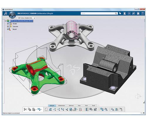
Functional Generative Design. Aimed at engineers who are not design and optimi- zation software experts, this new workflow enables the user to perform trade studies and arrive at the best conceptual part shape without resort to tedious, manual reconstructions. Source: Dassault Systèmes


Additive manufacturing (AM) was first developed for polymeric materials with the goal of producing prototype object geometries. Also known as 3D printing — because it can be used to “print” three-dimensional solid geometries of almost any shape from a digital model of the solid — it gave part designers a means to develop prototypes without material removal or the need to make molds. There were enormous economic benefits from this product development innovation — 3D printing is a tool-less manufacturing process and, with refinements, has more recently begun to produce finished products of polymeric, metallic and ceramic materials.
However, because material properties are directly related to their composition and microstructure, it is essential that the latter be considered in the overall development of AM for the future, if material performance is a goal.


Of primary interest when AM printing with fiber-reinforced materials is the need to predict and measure the anisotropic deformation that occurs in the printed element during the process because the printed shape can differ from that of the initial digital model. Thus, simulations that model AM must include a description of anisotropic element shape-change during deposition to allow adjustment of the deposition process to achieve the desired overall geometry as specified in the initial digital description. In addition, simulations should provide the in situ material properties as well. By so doing, the performance of the printed element can be anticipated.
Deposition of anisotropic materials is not well understood. Flow orientation of discontinuous fiber suspensions is determined by the kinematics of the fluid flow. Thus, nozzle design for 3D printing with fused deposition can yield flows where in the fiber phase is well collimated and aligned with the flow direction, or in some cases, transverse to the flow direction. In either case, the resulting properties of the solidified material are highly anisotropic and depend on the relative volume fractions and properties of the fiber and continuous phases.
Another deposition process uses continuous fibers that are fully or partially impregnated with a matrix phase. Here, the matrix phase is brought to the liquid state when the system is deposited. Solidification and adhesion then yield the local geometry. The matrix phase also can be in fiber form and commingled with the reinforcing fibers. The challenge is to provide local pressure to assure fiber/matrix consolidation during deposition, while allowing for flexibility in deposition geometry. Of course, the continuous deposition system must also provide a mechanism for cutting the carbon fiber during the process in order to provide the full range of deposition geometries. Typically, these systems are restricted to laminate structures with thin curvilinear geometries.
To ensure these materials are reliable and function, as built, the way we need them to, it is essential to understand the material properties and the printing processes that can be employed. The use of physics-based tools with multi-scale simulations helps us address these challenges.
In addition, because parts manufactured with AM processes today can be more organic in shape, lighter and more complex than parts made with traditional processes, engineers and manufacturers are changing the way they design parts. However, there are many limitations in today’s computer-aided design (CAD) tools, including the lack of ability to access and consume simulation information in an efficient manner. It is doable, but the process is manual and tedious and requires multiple software tools. Further, the disconnect between toolsets has prevented designers from quickly iterating shapes based on the desired performance.
The additive manufacturing industry, therefore, has challenged the design community to develop an efficient product engineering platform where the barriers between design, optimization and simulation would be broken and optimized parts could be explored in the design environment. Challenged by a major aerospace OEM, Dassault Systèmes developed a physics-based, simplified workflow called Functional Generative Design, aimed at engineers who are not experts in conventional design and optimization software.
The designer applies the structural loads and boundary conditions directly to the CATIA geometry, and organizes these into load cases as needed. A topology optimization problem can then be undertaken. The objective function (maximize stiffness, minimize mass, or maximize the first natural frequency) is selected. Constraints are assigned, and then the optimization is initiated. Running in the background is the Abaqus finite element analysis solver, and Tosca, a non-parametric topology optimization tool that identifies the optimal material distribution within the design space. Together, they will generate the ideal shape.
Once the user is satisfied with the shape, the solid body can be calculated. If the designer wants to explore alternative shapes, he or she can use the Variant Manager to perform trade studies. The Variant Manager allows the user to review the concepts and assess the results based on KPIs (key performance indicators, see the screen shot below). Once the trade study is complete, the designer selects the best possible conceptual shape.
In a traditional design environment, at this point, the step of taking the optimized results back to CAD through a geometry reconstruction process is a highly time-consuming and manual process — the designer would have to manually reconstruct the now non-integrated optimized part. Moreover, the associativity with the original design might be lost. But because the new workflow captures the physics of the materials and the process, the designer is able to simulate the stress and distortion the material will be under during the print build, and then calibrate the material for the build and analyze the print temperature and residual stress to account for these factors. This closes the gap between the design and the as-built product, and enables the designer to optimize the process cost, schedule and quality. The designer, for the first time, has access to the optimized part.
AM of fiber-reinforced composite materials provides a platform to examine true structural optimization wherein the external part geometry and the internal microstructural fields are optimized simultaneously. For anisotropic materials, this scenario can provide for optimization of fiber/matrix preforms that map the needed properties to the geometric locations that meet specified loading conditions, thereby significantly reducing structural weight. There are numerous multi-functional requirements for typical engineered systems, and the 3D printing approach to design provides an opportunity to meet customer needs with substantially more degrees of freedom in design than conventional homogeneous systems.


.jpg;maxWidth=300;quality=90;format=webp)


Related Content

Materials & Processes: Fabrication methods
There are numerous methods for fabricating composite components. Selection of a method for a particular part, therefore, will depend on the materials, the part design and end-use or application. Here's a guide to selection.
Read More
Composite rebar for future infrastructure
GFRP eliminates risk of corrosion and increases durability fourfold for reinforced concrete that meets future demands as traffic, urbanization and extreme weather increase.
Read More
Plant tour: Joby Aviation, Marina, Calif., U.S.
As the advanced air mobility market begins to take shape, market leader Joby Aviation works to industrialize composites manufacturing for its first-generation, composites-intensive, all-electric air taxi.
Read More
One-piece, one-shot, 17-meter wing spar for high-rate aircraft manufacture
GKN Aerospace has spent the last five years developing materials strategies and resin transfer molding (RTM) for an aircraft trailing edge wing spar for the Airbus Wing of Tomorrow program.
Read MoreRead Next

From the CW Archives: The tale of the thermoplastic cryotank
In 2006, guest columnist Bob Hartunian related the story of his efforts two decades prior, while at McDonnell Douglas, to develop a thermoplastic composite crytank for hydrogen storage. He learned a lot of lessons.
Read More
Composites end markets: Energy (2024)
Composites are used widely in oil/gas, wind and other renewable energy applications. Despite market challenges, growth potential and innovation for composites continue.
Read More
CW’s 2024 Top Shops survey offers new approach to benchmarking
Respondents that complete the survey by April 30, 2024, have the chance to be recognized as an honoree.
Read More