
How Are Composite Bridges Performing?
Ongoing monitoring and inspection demonstrates that composite bridge decks meet or exceed expectations.


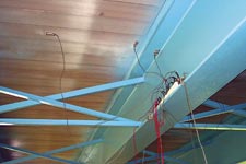
Source: NCCThe Greene County bridge is instrumented for live load testing with an array of strain gauges.
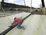
Source: LJB Inc.Salem Ave. bridge construction took place in 1999, and its performance has been extensively studied since.

Source: Univ. of CincinnatiLive load testing of Salem Ave. bridge in progress, performed with the aid of fully loaded trucks.

Source: NCCThe load test in progress, with a fully loaded dump truck.
Worldwide, there are at least 175 vehicular bridges and 160 pedestrian bridges in service today that incorporate composites. That's a fair number, considering that 10 years ago, there were about a dozen. The rapid proliferation is due to growing recognition of composites' structural durability, corrosion resistance and light weight, and how those properties translate to fast installation, better load-carrying capability (because dead load or bridge self-weight is so low) and virtually no maintenance over the life of the bridge. With the U.S. infrastructure on shaky ground — earning a D+ grade from the American Society of Civil Engineers in its latest infrastructure report — the demand for composites in civil construction will continue to expand. (For a complete list of all in-service composite bridges see the Market Development Alliance of the FRP Composites Industry's Web site: www.MDAcomposites.org.)
Yet, even with hundreds of bridges in service, many civil engineers remain unconvinced. In most cases, composite decks are considered demonstration experiments, placed on out-of-the-way, low-traffic routes. "It's like breaking into any new area. First, you walk on, you start small, then work your way up to more demanding applications," says Scott Reeve, vice president of the National Composites Center (NCC, Kettering, Ohio, U.S.A.) and an active advocate for composites in infrastructure. "You have to get the owners comfortable with the new technology."


To that end, most composite bridge installations were either instrumented during construction or have been routinely tested and inspected so that bridge deck performance can be assessed. Here, selected composite bridge projects are revisited, with an examination of their performance, based on test data.
C4I IN OHIO
NCC is spearheading a campaign to grow the composite bridge market in Ohio, through its Composites FOR Infrastructure (C4I) program initiated in August 2001. To date, four composite decks, fabricated by Martin Marietta Composites Inc. (Raleigh, N.C., U.S.A.), have been installed under C4I, with more to follow. The C4I program builds on NCC's original state-funded Project 100, kicked off in 2000, under which nine composite bridges fabricated by Hardcore Composites LLC (New Castle, Del., U.S.A.) were installed across the state. Reeve explains that to help gain acceptance of the bridges, the NCC acts as a liaison between the bridge owners, county engineers, Ohio's Department of Transportation officials, and the composite deck manufacturers. NCC personnel follow up each installation with routine yearly inspections and live load tests and give the counties periodic feedback.
The most important item on the inspection checklist is evidence of cracking in the pavement overlay, says Reeve. Cracks indicate differential thermal expansion and movement among the steel supporting girders, the composite deck materials, concrete abutments and the asphalt, and might indicate excessive movement of a deck panel, which in turn could indicate connection problems.
"A critical element on these bridges, as with any composite structure, is the connection details between the composites and other materials," says Reeve. Several of the NCC program bridges use a bolted-on clip to connect the deck to the underlying girders — inspectors pay particular attention to whether such connectors have loosened over time, since excess flex can result in premature wear. In several cases, "haunches" or shims have been required to level the deck on the girder flanges, or to bring the deck up to the level of the approach roads. Inspectors look for good solid contact between the shims and the underside of the deck, and add shims if needed. While pultruded decks tend to be very flat, molded, resin-infused decks can have more variation, and may require additional shims for a good fit.
In October 2002, NCC supervised a live load test of the Green County composite bridge, shortly after deck installation. The 221-ft long and 32-ft wide three-span bridge, featuring a new pultruded fiberglass/vinyl ester deck supplied by Martin Marietta Composites, was tested using a fully loaded, dual-axle dump truck weighing 34.5 tons (69,000 lb). Forty-four strain gauges were attached to the underside of the deck to evaluate the behavior of the structure. Deflection gauges also were attached to a bar placed between the lower flanges of two adjacent girders, to measure actual downward deflection of the deck under load. Thin rods extending upward made contact with the deck's lower skin and were pushed downward by the truck's weight.
Reeve reports that the deck deflected 0.047 inches, or less than 40 percent of the allowable 0.118-inch deflection under current industry guidelines for the bridge's size and traffic load (the allowable deflection is determined by the distance between girders divided by a factor of 800). This guideline is being considered as a requirement by industry regulators such as the American Association of State Highway and Transportation Officials (AASHTO). The maximum measured strain in the transverse direction was 297 micro-inches (or 0.000297 inches/inch). Because composite decks are designed primarily for stiffness — to minimize deflection and, therefore, driver anxiety — as well as for corrosion resistance, they end up being over-designed and much stronger in terms of strain to failure, says Reeve.
"Aircraft structure is generally designed to 5,000 micro-inches," he states. "Glass composites won't fail until you start getting up around 20,000 micro-inches of strain — here we're seeing 1 percent of that."
OHIO'S FIRST ALL-FRP BRIDGE
On July 25, 1997, the first locally funded Ohio "Tech 21" composite bridge was opened to traffic in Butler County, Ohio. The bridge was the third composite vehicular bridge in the U.S. A team made up of representatives from the Butler County engineer's office, Martin Marietta Composites, LJB Engineers & Architects, Wright Patterson Air Force Base, Foster-Miller Inc. (Waltham, Mass., U.S.A.) and Bridge Diagnostics Inc. (Boulder, Colo., U.S.A.) devised an impressive in-service monitoring plan that involved 50 permanently embedded vibrating-wire strain gauges for measuring axial and vertical strain, bondline slip and deck tilt. Each sensor also measured temperature. Two thermistors were incorporated into the deck to record the temperature profile of the entire superstructure. Wright Patterson employed Foster-Miller to install 18 Bragg grating fiber optic sensors for monitoring strain, while four sapphire wire chemical fiber optic sensors, installed within the adhesive, monitored the condition of the bridge's epoxy bonds. Forty-six additional temporary sensors were mounted during short-term live load tests, conducted immediately after the bridge was installed, in January 1998, and again in July 1998 and January 2000.
The Tech 21 bridge is somewhat unique in that the entire structure — support beams and deck — is composite. Three 33-ft long hollow box beams, 2 ft high and approximately 3 ft wide, were fabricated by Acme Fiberglass Inc. (Hayward, Calif., U.S.A.) using multiple plies of stitched triaxial E-glass fabrics supplied by VectoryPly Corp. (Phenix City, Ala., U.S.A.) and wet out with polyester resin from Ashland Specialty Chemical Co., Composite Polymers Div. (Columbus, Ohio, U.S.A.). Design stiffness was achieved with additional unidirectional E-glass plies along the undersides of the beams and several interior stiffener frames. The deck, consisting of pultruded trapezoidal profiles with upper and lower skins, was integrally laminated to each box beam, and then adhesively bonded together in the field to form a continuous surface.
Nine of the 18 Bragg grating fiber optic sensors were installed within the beam underside laminates, three in each beam. The remaining nine were placed on the inside surfaces of the hollow beams once the bridge was installed. The Bragg sensors operate by reflecting a specific wavelength of light to a grating of specific size. When the structure deflects, the sensors bend or stretch slightly, which changes the wavelength of the reflected light. Instrumentation monitors the sensors' output and correlates the wavelength change to a strain value.
A data acquisition system collected the strain and temperature readings once per minute, then averaged the data for hourly conditions. The bondline sensors were checked only during live load test cycles with large single- and tandem-axle trucks.
Dean Foster, a former Butler County engineer who left office at the end of his term in December 2000 and who is now with Wright Patterson, says that after six years the bridge remains in service and is functioning as expected, with no visible signs of degradation. A flood event did leave some minor scrapes in the laminate on the underside of the structure. According to Foster, the bridge strain monitoring data collected between 1997 and 2001 exactly fit published mathematical creep data. "Models predict that there will be 2.5 mm of sag or additional deflection over a 50-year period, and it appears that the bridge data are following that trend precisely," says Foster.
While the Bragg optical sensors initially operated, they were not a good choice for long-term monitoring, Foster reports, because they require frequent recalibration, a cost that the county could not afford. Unfortunately, the current county engineer terminated the data collection and monitoring program in August 2001, and there are no plans for future testing, according to Foster. But, the four years of data collection helped to build an engineering database that demonstrates the benefits of composites to the civil engineering community, he concludes.
SALEM AVE.'S AGGRESSIVE EXPERIMENT
The Ohio Department of Transportation undertook an ambitious research project in 1999, with support from the Federal Highway Admin. (FHWA), to evaluate FRP deck materials and performance. The 207m/673-ft-long Salem Ave. Bridge on Route 49 in Dayton crosses the Great Miami River, with two parallel, five-span bridges. Four different composite deck types, from four different manufacturers, were installed on one bridge, making it the largest composite deck installation at the time. The manufacturers included Hardcore Composites, Creative Pultrusions Inc. (Alum Bank, Pa., U.S.A.), Infrastructure Composites International (ICI, San Diego, Calif., U.S.A.) and Composite Deck Solutions LLC (Dayton, Ohio, U.S.A.). The second bridge had only the Composite Deck Solutions deck system (described below).
The Creative Pultrusions deck consisted of pultruded trapezoidal profiles, bonded together. The Hardcore segment was molded in a vacuum infusion process and made with fiberglass skins and fiberglass fabric-wrapped foam core blocks wet out with Dow DERAKANE (Midland, Mich., U.S.A.) vinyl ester resin. ICI's segment was cored with a sinusoidal fiberglass core material (described in the following section on Kansas bridges). Each composites manufacturer produced panels that were 216 mm/8.6 inches thick, 12.2m/40 ft long and 2.4m/8 ft wide, and all were covered with a thin (9.5 mm/0.4 inch) polymer concrete wearing surface. Finally, the fourth Composite Deck Solutions segment (as well as the deck on the second companion bridge) was a hybrid made up of pultruded fiberglass stay-in-place forms filled with high-strength concrete, with internal fiberglass reinforcing grids.
The composite panels were attached to the underlying steel girders with a combination of epoxy adhesive and studs welded to the top flanges of the girders every 1.2m/4 ft. Holes were drilled in the panels to accept the studs, and the holes were filled with non-shrink grout. Panels from each manufacturer were separated by an elastomeric-filled expansion joint, and were not connected to each other.
Several groups, including the University of Cincinnati, University of Kentucky, University of Maine, Ohio University, and the U.S. Army Cold Regions Research and Engineering Laboratory have participated in monitoring the performance of the bridge. Laboratory static and fatigue tests and material coupon tests were conducted in Phase I, followed by actual live load tests, using fully-loaded trucks along with modal analysis — that is, impacting the deck with an impact hammer and measuring the frequency and modal response. A system of strain gauges and other instruments, including acceleration response sensors, were placed to measure deflection, strain, and movement of the various panels.
The most recent test was completed in September 2003, says Tim Keller, a state bridge engineer with the Ohio Department of Transportation. While actual test results aren't yet available, Keller reports that the bridge has provided a wealth of information and a good "lessons learned" case study. "We've gained a lot of useful data," he says. "Composite decks offer good properties, but you also have to be careful, particularly with the different coefficients of thermal expansion (CTEs) of the composite material as compared to the concrete or steel support girders."
Those differences, combined with four dissimilar designs and manufacturing approaches, unfortunately led to unequal movement of the various manufacturer's panels with respect to each other. There also were issues with achieving solid connections between the composite decks and the girders, reports Keller. Given the experimental nature of the project and the design differences, the DOT decided to remove the composite deck sections supplied by Hardcore and ICI. The removed segments were replaced with conventional steel-reinforced concrete decks. The pultruded composite deck remains in place, but Keller says that it's a challenge to keep the thin overlay on that segment from cracking and debonding, given the traffic volume and loads on the bridge. The fourth, hybrid design of concrete reinforced with composite grids is working well, although in an effort to save weight, the concrete cover over the composite reinforcement was reduced — perhaps too much — which has led to some cracking in the concrete. The cracks have been sealed, and Keller says that even if water ingress occurs, the composite grid won't rust.
Keller points to a concern for all bridge engineers regarding responsibility for the design and proper field installation of the girder/deck connections. "Who owns those connections?" he asks. "In our opinion, they should be the responsibility of the composite deck manufacturer." Even though the decision to remove two of the composite material sections was a setback, Keller still views the project as a success, despite high up-front costs. "Now is the time to observe the bridges we have installed in Ohio and see how they're performing," he says.
KANSAN COMPOSITE DECK REPAIRED
The very first all-composite bridge in the country was the No Name Creek span, placed in Russell, Kan. in November 1996 (see CT January/February 1997, p. 7). The cored deck was designed and fabricated by Kansas Structural Composites (Russell, Kan., U.S.A.) and because of its short 23-ft length, it was supported only on four steel pilings — support girders weren't required. The bridge is still in service and performing well, says Kansas Department of Transportation engineer David Meggers. Other than initial load testing, no ongoing structural testing has been performed, reports Meggers, but the bridge is inspected routinely, and no problems have been observed. A follow-up load test may be conducted within the next year, for documentation purposes. "The No Name span is so overdesigned, it's probably never going to change," notes Meggers.
A composite span installed in 1999 in Crawford County, Kan. also has demonstrated durability despite suffering damage. One of two identical composite bridges four miles apart on the same road, the Crawford deck is a honeycomb-like sandwich design, using a very large-cell, corrugated core like that found in cardboard boxes (see CT April 2000, p. 16). The core, devised by Infrastructure Composites International in collaboration with Kansas Structural Composites, was made with chopped strand mat from Saint-Gobain Vetrotex (Valley Forge, Pa., U.S.A.), with straight vertical webs bonded to and alternating with sinusoidally shaped webs to create a cost-effective but very strong core material. The face skins were made with biaxial and unidirectional E-glass fabrics supplied by Saint-Gobain BTI Inc. (Brunswick, Maine, U.S.A.). Polyester resin was supplied by AOC (Collierville, Tenn., U.S.A.).
Meggers says that the highway approach profile on one end of the bridge, which had excessive asphalt overlay at the time of bridge installation, had settled and changed in such a way that it created a kind of "ski jump." Cars and trucks were launching from the approach, impacting the first composite bridge panel, with tremendous force. The repeated impacts, which Meggers says were excessive for any material, damaged the upper skin of the cored composite deck, working it loose from the underlying structure. After shaving the approach road to remove and level the asphalt, a temporary deck repair was easily made by cutting out the damaged skin area, cleaning the underlying core and bonding on a new section of wet-out fabric material. The repaired area was securely clamped to the underside of the deck with two long bolts held by large circular washers.
Meggers says that inspection showed that despite the damaged upper skin, the deck did not fail, but is still structurally sound, a tribute to its materials and design.
"This was actually a great opportunity to assess a damaged panel," says Meggers. "It was an experiment going in, and now we know that we can easily and quickly fix a deck in the field." A permanent repair will involve removing the asphalt on that panel, completely removing the upper skin, and replacing it with a new skin, a process that should take about eight hours to complete.
Meggers reports that vandalism, though attempted, has not harmed the deck. "Someone keeps trying to shoot the bridge reflectors with a rifle," he reports. "You can see small marks where the bullets have hit the deck, but they haven't penetrated the laminate."
Meggers, a strong advocate for composites in transportation projects, reports that Kansas is continuing research on using low-weight, easily-transportable composite decks as temporary spans for detours during construction. His group also is evaluating guardrails — composite, steel and concrete — for composite spans and the best types of deck/rail connections. Crash tests are currently being conducted at the University of Nebraska to evaluate various configurations. Says Meggers, "We have learned a tremendous amount about composites and we're moving forward. We can always improve and do something better."
NEW YORK BRIDGES WELL-TESTED
The New York State Department of Transportation (NYSDOT) opened its first composite bridge in 1998. The Route 248 Bennetts Creek crossing was a resin-infused, cored structure with integral parapet railings, fabricated by Hardcore Composites (see CT April 2000, p. 14), with a 30° skew angle and a 2° cross slope. Because of the short 25-ft span, the 62-cm/24-inch-thick deck rests directly on new concrete abutments, without supporting girders. The E-glass/vinyl ester deck was fabricated in two sections, with a crowned center longitudinal keyway joint to create the cross slope. The sections were field-bonded with epoxy resin.
Before the deck opened for traffic in October 1998, it was load-tested to prove structural integrity and establish a baseline for future monitoring. Four fully loaded, 10-wheel dump trucks were parked on the bridge while installed strain gauges monitored strain and deflection. The maximum strain recorded at any gauge was 204 micro-inches (0.000204 inches), less than half the 600 micro-inches predicted by finite element analysis during design. Maximum deflection at mid-span was less than 3.5 mm/0.125-inch, considerably less than the L/800 AASHTO limitation of 8.8 mm/0.35 inch.
Five follow-up load tests have been conducted since installation. According to Sreenivas Alampalli, acting director of the NYSDOT Transportation Research and Development Bureau (Albany, N.Y., U.S.A.), the subsequent strain data are almost identical to the initial readings, indicating satisfactory performance without any structural problems. Alampalli's group also has performed detailed static finite element analysis (FEA) to evaluate failure mechanisms of the superstructure, local buckling and the effect of a vehicle hitting the concrete-filled composite parapet railing. Tensile and shear tests were conducted on E-glass/vinyl ester coupons to obtain material properties for use in the analysis. The modeling showed that first-ply failure would not occur until maximum deflection reaches three times the AASHTO allowable deflection, which would represent a load on the superstructure 10 times greater than the four-truck loading conducted during the proof test. And, the superstructure has the ability to resist vehicle impacts on the parapet.
"Structurally, the bridge is performing well," says Alampalli. "We had a small delamination on the underside of the deck, which was easily repaired. A bigger issue was the wearing surface." The installation called for a 9-mm/0.38-inch-thick polymer concrete overlay supplied by Transpo (New Rochelle, N.Y., U.S.A.) as the wearing surface, which was applied by Hardcore during deck fabrication. Alampalli says the very thin overlay didn't wear well under traffic loads, and the surface was renewed in June 2000 by sandblasting the original surface, then applying a thicker coat of the same material. Since then, the new surface has performed satisfactorily, reports Alampalli.
BRIDGE DESIGNS IN ABUNDANCE
The Constructed Facilities Center at West Virginia University (WVU) has been involved actively in the design, repair, rehabilitation and performance-monitoring of composite bridge decks and structures installed in West Virginia and other locations. A group of WVU researchers has developed a low-profile, 10 cm/4-inch thick composite beam deck design, weighing a mere 10 lb/ft2. The beam is a series of pultruded E-glass/vinyl ester profiles supplied by Bedford Reinforced Plastics Inc. (Bedford, Pa., U.S.A.), bonded together to create a deck panel. A combination of fabrics, fiber mat and rovings result in a final fiber volume fraction of about 50 percent.
The ultrathin deck has been extensively tested in the laboratory, says WVU's Dr. Hota Gangarao. Subjected to a static load test, the deck withstood over 40,000 lb of load, deflecting about 38 mm/1.5 inches before failure. Recorded strain at failure was about 3,000 micro-inches. The 4-inch WVU deck has been installed on the Pleasant Plain Rd. bridge in Montgomery County, Ohio.
Each of the bridges in this article, and many others — including monitored panels at the University of California San Diego, the Route 896 composite bridge in Glasgow, N.J. (extensively monitored by Dr. John Gillespie and others at the University of Delaware), several bridges in Oregon and a number of European spans — have contributed to a better understanding of composites' performance in critical civil structures. As is true with any material, designing for the particular application is the key to optimum composite performance. "Even beyond the design, the testing and the monitoring that we do is very important," NCC's Reeve concludes, "because we want to be able to answer the questions that are of current interest to the engineering community, and that is, How do these materials perform?"


.jpg;maxWidth=300;quality=90;format=webp)


Related Content

Why aren't composites synonymous with infrastructure?
The U.S. seems poised to invest heavily in infrastructure. Can the composites industry rise to the occasion?
Read More
Materials & Processes: Composites fibers and resins
Compared to legacy materials like steel, aluminum, iron and titanium, composites are still coming of age, and only just now are being better understood by design and manufacturing engineers. However, composites’ physical properties — combined with unbeatable light weight — make them undeniably attractive.
Read More
Composite rebar for future infrastructure
GFRP eliminates risk of corrosion and increases durability fourfold for reinforced concrete that meets future demands as traffic, urbanization and extreme weather increase.
Read More
CW Tech Days webinar addresses emerging composites opportunities in infrastructure, construction
Attend this Dec. 1st interactive webinar sponsored by Composites One, where experts will review and evaluate the composite materials, processes and applications that should and will be considered for use in these markets.
Read MoreRead Next

From the CW Archives: The tale of the thermoplastic cryotank
In 2006, guest columnist Bob Hartunian related the story of his efforts two decades prior, while at McDonnell Douglas, to develop a thermoplastic composite crytank for hydrogen storage. He learned a lot of lessons.
Read More
CW’s 2024 Top Shops survey offers new approach to benchmarking
Respondents that complete the survey by April 30, 2024, have the chance to be recognized as an honoree.
Read More
Composites end markets: Energy (2024)
Composites are used widely in oil/gas, wind and other renewable energy applications. Despite market challenges, growth potential and innovation for composites continue.
Read More