
Future combat helmet: Promising prototype
Tape laying, thermoforming methods hold hope for rapid coforming of thermoplastic shell and ballistic liner for U.S. Army’s future warfighter headgear.

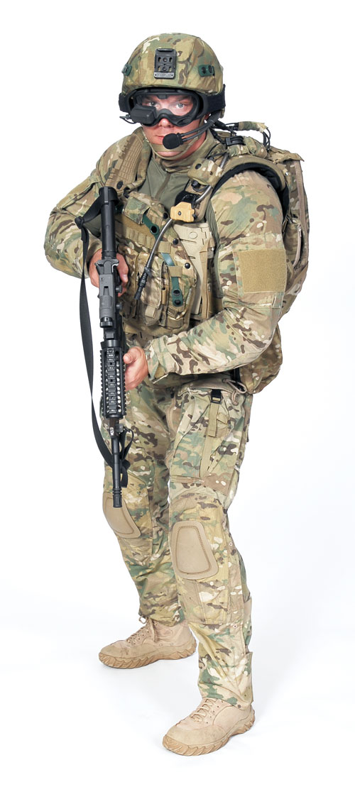
The Future Force Warrior project, an R&D effort undertaken several years ago by the Natick Soldier Research and Development Center and the U.S. Army Research Laboratory, included a mandate for a new helmet that could accommodate an expected increase in the number of integrated electronics and sensing systems. Glenwood Springs, Colo.-based Fiberforge helped develop a coformed thermoplastic prototype that paved the way for ongoing research. Source: Natick Soldier Systems Center
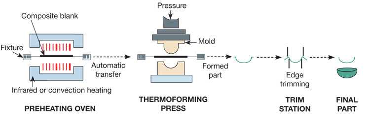
A schematic of the Fiberforge-developed helmet thermoforming process steps includes (left to right) preheating of a tailored blank, shuttling it into a mold within a press for thermoforming, then trimming the part to final configuration. Source: Fiberforge

Step 1: These renderings show the overall helmet concept. The outer structural shell was made with carbon/PPS; the inner ballistic shell was fabricated from DuPont Kevlar with a matrix of thermoplastic polyurethane (shown in yellow). Source: Fiberforge
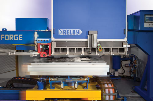
Step 2: Fiberforge’s patented RELAY station was used to create the tailored blank for the helmet’s outer structural shell. Its flat indexing table moves in three axes under a stationary layup head that dispenses and cuts the fiber-reinforced thermoplastic tapes. Source: Fiberforge
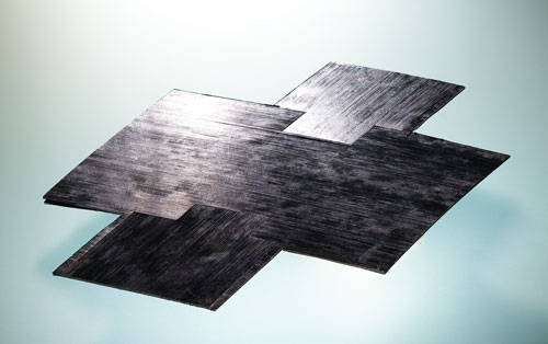
Step 3: An example of a tailored blank developed for the outer structural shell. Source: Fiberforge
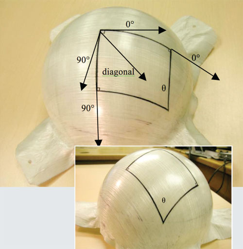
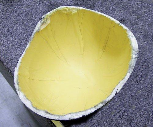
Step 4: This part from a hemispherical dome molding trial shows the problem of “trellising,” the result when 0°/90° fibers do not maintain their orientation away from the helmet crown and, therefore, overlap to produce wrinkles. Source: Fiberforge
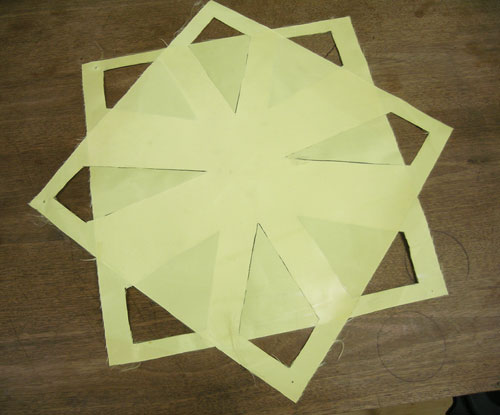
Step 5: One example of the many darting experiments attempted on the Kevlar material in an effort to build a molding blank that minimized wrinkling in the ballistic shell. Source: Fiberforge
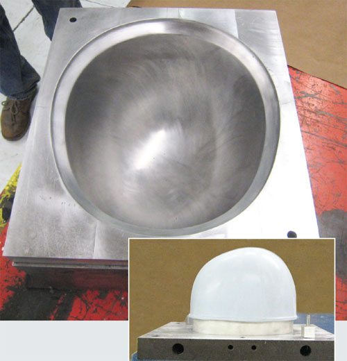
Step 6: The mold for the helmet trials consisted of an aluminum cavity mold and a cast silicone core that fit inside the cavity to apply pressure on the inside of the helmet shape. Source: Fiberforge
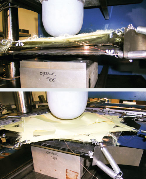
Step 7: A key to the process was fixturing of the two blanks within the shuttle frame (the Kevlar above and the carbon below) to accurately position them prior to molding. A film adhesive was placed between the two blanks, which were comolded in one step. Source: Fiberforge
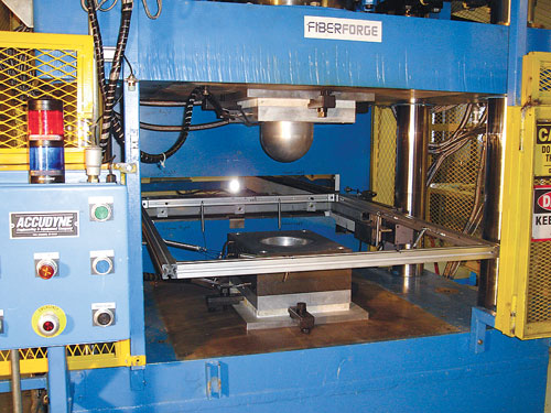
Step 8: The shuttle was moved into position in the thermoforming press, shown here in an earlier photo, for forming. Source: Fiberforge
Step 9: A finished prototype helmet, after trimming. Through numerous trials, the amount of wrinkling was successively minimized with better darting strategies. Source: Fiberforge


In the past two decades, ubiquitous armed conflicts have spurred tremendous growth in armor materials and designs. Those who watch the armor market expect demand to continue. For example, a 2009 study by the military armor research specialists at Vector Strategy (Southern Pines, N.C.) predicts that $6 billion (USD) in military body armor will be procured by the U.S. military between 2009 and 2015.
Composites now play a huge role in this market (see “Structural armor or armored structures?” under "Editor's Picks," at right), having steadily displaced traditional materials since the early 1980s. For military helmets, in particular, lightweight composite designs reinforced with aramid, ultrahigh molecular weight polyethylene (UHMWPE) and other fiber types, often in hybrid combinations, have long since replaced the steel “pot” helmets of World War II and the Vietnam War era. The current trend is toward thermoplastic helmets, and such designs are presently under evaluation by the U.S. Army and Marine Corps for their developmental Enhanced Combat Helmet (ECH) program. The aim is to up the ante for warrior protection yet maintain the weight of the current helmet — a tall order, according to those familiar with helmet design.


In conjunction with this program, Fiberforge (Glenwood Springs, Colo.) has worked closely with the U.S. Army Research Laboratory (ARL, Adelphi, Md.) to develop a reinforced-thermoplastic helmet design paired with a cost-effective manufacturing strategy. Several years ago, the ARL asked Fiberforge to assist in the Future Force Warrior (FFW) helmet program, initiated and executed by the Natick Soldier Research and Development Center (Natick, Mass.), says ARL’s investigation sponsor Shawn Walsh. “FFW was a visionary program,” he recalls. “It allowed for total rethinking of how the soldier might perform his or her mission in the current and future Army.” Because the future helmet is envisioned as a sophisticated piece of equipment that will integrate more electronics and sensing systems, he explains, the Army will need “a helmet that is lighter than existing thermoset composite models, yet offers more protection.”
Hybridized helmet design
Overseen by Natick, FFW was a trial program limited to production of a viable FFW helmet prototype, but Walsh points out, “It allowed me ... to transition the novel thermoplastic hybridized helmets we developed under FFW into a more generic and pervasive manufacturing capability. This ... capability is now being exercised in the development of the Enhanced Combat Helmet.”
Tom Campbell, Fiberforge’s applications engineer for the FFW helmet program, says the prototype’s design began with ARL’s performance specifications, specifically, a given areal weight of 8,540 g/m² (1.75 lb/ft²). “If we met this areal weight target,” he points out, “the helmet would have sufficient thickness and performance to meet the Army’s ballistic and overall weight goals.” Campbell explains that the helmet was envisioned with two components: a carbon fiber-reinforced thermoplastic outer shell, for stiffness and wear resistance, bonded to an inner aramid fiber/thermoplastic ballistic shell. The nominal thickness of the helmet would be approximately 9.2 mm/0.37 inch, and the thickness variation from helmet to helmet would be minimized.
Materials for the trial were provided by ARL. For the outer structural shell, ARL supplied a prepreg tape made with Hexcel’s (Dublin, Calif.) AS4 carbon fiber in a polyphenylene sulfide (PPS) resin matrix manufactured by TenCate Advanced Composites USA (Morgan Hill, Calif.). PPS was chosen as the tape’s matrix because of its toughness, high stiffness and wide service temperature range. “Given the relatively low weight budget available for the carbon fiber shell and the need to improve helmet stiffness, matrix modulus was a key factor in the resin choice,” Campbell notes. “With a tensile modulus of 3,600 MPa/522,136 psi, PPS has more than twice the modulus of two alternative resin systems that we considered — polypropylene and polyamide 6.” For the ballistic shell, ARL secured DuPont Kevlar 49 aramid fiber, manufactured by DuPont Advanced Fiber Systems (Richmond, Va.), in a biaxial woven fabric form, with a film of proprietary thermoplastic polyurethane laminated on one side.
The operative key to the helmet’s development, however, was Fiberforge’s forté, the automated processing of thermoplastic materials. Specifically, the company designed and developed a molding process consisting of four steps: 1) automated layup of composite material on its patented RELAY Station tape layer to create a preform or tailored blank, 2) blank consolidation, 3) thermoforming and 4) trimming. The challenge, says Campbell, was to adapt the process to create a helmet shape and thickness that would meet the Army’s specifications: “Obviously we wanted to make the process as automated as possible, but there was a lot of trial and error to optimize the process.”
Manufacturing a dome
The first step involved the creation of a “tailored blank” or flat stack of composite material for the helmet’s outer structural shell, using the RELAY Station. Given the areal weight of the carbon/PPS tape, at 386g/m² (0.079 lb/ft²) per ply, and the helmet’s areal density goals, a maximum of three plies of tape were placed by the RELAY’s automated laying system. The system’s flat metal table moved in three axes — x, y and rotationally around the z axis — under a Fiberforge-designed stationary layup head that dispensed the tape. The table and head were controlled by TailorGen CNC software, developed by Fiberforge. TailorGen generated the machine code file to create the 2-D blank in less than three minutes, in a proprietary shape that would permit it to be thermoformed successfully into its intended 3-D shape. Because the tape-laying system can cut tape courses at a variety of angles, the software not only produced a layup pattern for the helmet’s structural shell with the most efficient shape, but it also calculated cut angles that minimized scrap.
Laying up the blank for the inner ballistic shell proved more challenging: The Kevlar fabric for the ballistic shell was supplied in roll form, so it had to be cut to shape and layed up by hand. The inner blank also was thicker — ultimately, 39 plies of the material were required to produce the desired ballistic performance. Further, says Campbell, the principal difficulty was that the helmet’s compound-curve dome was one of the trickiest to mold successfully without wrinkling. When the 0/90 material layup was formed into a complex curve, the angle between the warp and weft fibers changed as the flat blank conformed to the mold geometry.
As shown in Step 4 (see photo, at right), the shear angle between warp and weft progressively narrowed as the fibers progressed downward away from the crown, a phenomenon known as “trellising.” As this in-plane shear angle continued to decrease, local fabric thickening occurred where the fibers began to bind, and this thickening eventually caused the material to fold and wrinkle. “We had to come up with a strategy, using cutting and darting, to minimize the wrinkling, given that such a thick section was required by the helmet design,” Campbell says, recalling that “it was an interactive process.”
Different approaches were tried: those that required no cuts, others that involved cuts without material removal and the best solution, says Campbell, involving “significant” darting and material removal. During early trial molding runs, however, the darts tended to close up so their edges were nearly joined, which created a potential plane of weakness, says Campbell. To avoid having the darts thus aligned within the part, each dart was offset ply to ply within the blank, as shown in Step 5 (see photo at right). This also mitigated wrinkling in the final molded helmets.
The next step involved consolidation of the 3-ply structural shell blank. Essentially a high-temperature debulk, the task was accomplished by placing the blank between flat heated platens and compressing it at a pressure lower than the final forming pressure — a method that Fiberforge routinely uses. The exact temperature and pressure depend on the material type, but for the carbon/PPS, the pressure was ~200 psi/~1.38 MPa. The heat, pressure and subsequent cooling eliminated air pockets in the blank and yielded a better result during molding, reports Campbell. “The consolidation slightly melts the resin and forces any air out, resulting in fewer voids in the finished part,” he explains, emphasizing that “it’s a particularly important process step for higher-temperature thermoplastics.”
Unfortunately, the same steps were not possible for the Kevlar-reinforced ballistic shell blank. The hand-stacked blank was too thick to achieve through-consolidation within the inner layers.
Fixturing, heating and molding
After several process iterations, during which the outer and inner shells were formed separately, Fiberforge elected to coform the ballistic shell and structural shell in one step. This decision meant that prior to molding, stable fixturing of the blanks in relation to each other during preheating was a key process step.
Fixturing involved placing the blanks on a movable shuttle, which traveled through an infrared (IR) heating oven and then into the mold station, with the structural carbon/PPS on the bottom and the Kevlar/thermoplastic polyurethane on top, separated by an air gap. A thin sheet of urethane film adhesive was placed between the two blanks. Intended to enhance the bonding of the two materials during molding, the urethane had a melt temperature between that of the two composite materials. To position the preforms precisely where they needed to be in relation to the mold and each other, stiff springs were attached via hooks to the edges of each blank; tension was applied by attaching the springs to wires on a frame that surrounded the shuttle. Campbell notes that fixturing was important to process, and that different amounts of tension were needed for the two materials: “We had to do a ton of work, including designing equipment related to fixturing,” he notes. “How you hold the blank is really critical to getting it to form properly.”
Because the melting points of the two resins are different, the IR oven had to be modified to heat the polyurethane in the ballistic blank to a temperature of 150°C/302°F with the upper element while the lower element heated the PPS in the carbon blank to 330°C/626°F. When the blanks reached melt temperature, after ~15 minutes, the shuttle automatically moved them into the thermoforming press manufactured by Accudyne Engineering & Equipment Co. (Bell Gardens, Calif.)
The press was fitted with a heated aluminum mold cavity preheated to approximately 120°C/248°F. The press exerted 2,000 psi/13.8 MPa of downward pressure on a silicone core, which forced the stacked blanks into the cavity and applied hydrostatic pressure. “Our down-acting press applies more pressure at the crown than at the sides of the mold,” Campbell explains, “so the silicone core was designed to deform a bit to apply even pressure to the sides of the helmet during the forming step.” Pressure was maintained until the part cooled to a temperature of about 125°C/257°F, for a total molding time of about eight minutes. After demolding, the helmet edges were trimmed manually, using a diamond wet saw.
Lessons learned
The helmet project was a success in that it yielded many opportunities for improvement, says Campbell. Although initial trials produced parts with considerable wrinkling and wide variation in the thickness of the ballistic shell, improved darting schemes and adjustments in fixture tension and fixture spring location helped to minimize both problems. Further, it was clear that a switch to Kevlar thermoplastic tapes, rather than woven Kevlar cloth, would permit automated layup of the ballistic blank, shortening cycle time. Looking forward, Campbell believes the fixturing process also could be automated, using pneumatic tensioners and automated grippers. Other improvements could include a better heating method to reduce the Kevlar material’s time-to-temperature; active cooling of the mold to permit earlier demolding; and automated trimming, using waterjet or laser cutting equipment.
The FFW program insights helped Fiberforge transition to new helmet projects, the details of which are proprietary. “We’ve proven that rapid coforming of a thermoplastic helmet, using innovative techniques and automation, is possible,” Campbell concludes. “Now the challenge is to transition these methods to serial production.”
Read more about the Fiberforge fabrication process in “Tailored carbon fiber blanks set to move into steel stamping arena," under "Editor's Picks," at right.


.jpg;maxWidth=300;quality=90;format=webp)


Related Content

Scott Bader ATC begins Crestabond MMA structural adhesive production
Scott Bader’s Drummondville, Canada, facility has begun manufacturing and supplying composites-applicable adhesives to its North American customers.
Read More
Materials & Processes: Fabrication methods
There are numerous methods for fabricating composite components. Selection of a method for a particular part, therefore, will depend on the materials, the part design and end-use or application. Here's a guide to selection.
Read More
XlynX Materials BondLynx and PlastiLynx for low surface energy PP, PE substrates
Award-winning Xlynx materials use breakthrough “diazirine” technology to boost bond strength up to 950% as adhesives, primers and textile strengtheners.
Read More
XlynX Materials introduces PFAS-free BondLynx molecular adhesive
Improved version of BondLynx eliminates fluorine for a more sustainable adhesive option, while still outperforming conventional adhesive bonding strength.
Read MoreRead Next

Tailored carbon fiber blanks to move into steel stamping arena
Reduced scrap and cost driving forces behind new technique for automotive industry.
Read More
Structural armor or armored structures?
Either way, antiballistics engineers seek structural integrity and ballistic deterrence from a single design.
Read More
From the CW Archives: The tale of the thermoplastic cryotank
In 2006, guest columnist Bob Hartunian related the story of his efforts two decades prior, while at McDonnell Douglas, to develop a thermoplastic composite crytank for hydrogen storage. He learned a lot of lessons.
Read More