
Designing for dimensional stability in space
The accuracy of orbiting instruments depends on skillfully designed and manufactured composite components.


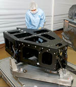
Source: Swales AerospaceThe optical bench for the Hubble Wide Field Camera 3, fabricated by Swales Aerospace.
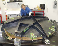
Source: Vanguard CompositesThe front reflector shell mold for the Telkom reflector also is used as an assembly fixture. The shell and star-shaped backup structure have been bonded together. The inner Kevlar shell has a similar backup structure.
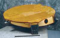
Source: Vanguard CompositesThe complex contours of the completed Telkom reflector assembly created challenging lay up conditions but are necessary for sending reflected radio frequency waves to a precise geographical location.

Source: Vanguard CompositesTable 1: Telkom 2.0 M Dual-shell Reflector requirements vs. predicted and actual measurements.
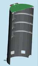
Source: JHU/APLAt top, an artist's section view of the CRISM baffle assembly shows the contoured vanes. Below, the actual baffle assembly is shown with vanes bonded in place.
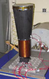
Source: Vanguard CompositesThe CTX Camera structure including heaters,is mounted to a vibration stand through an electronics box. A three-axis accelerometer is attached near the sunshade.
Vanguard Composites engineered and fabricated the optical bench assembly, the primary mirror baffle, the sunshade and sunshade fittings for the CTX Camera Structure, shown in linear cross-section in this artist's conception. The entire assembly, minus the electronics box, weighed just 3.7 kg/1.7 lb.
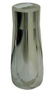
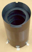
The highly polished aluminum mandrel for the sunshade cone
When a satellite or scientific instrument is sent into space, it must first survive the harsh launch environment and then be able to accurately orient itself in order to transmit data to and from specific locations in space or back on earth. Called "pointing accuracy," this ability depends to a great extent not only on the dimensional accuracy of payload structures, but their dimensional stability during transport into orbit and throughout an often lengthy mission.
At launch, there are major shock, noise and vibration loads encountered during the two minute period when the rocket leaves earth's environment. Once the space structure is in orbit, it is critical that all its components remain in the same relative position to each other despite extreme temperature changes. To accomplish this, designers and manufacturers must take into account a number of factors, including stiffness, thermal gradients and moisture, as well as build and assembly tolerances.


Composites play a key role in such missions. Their superior strength- and stiffness-to-weight and low coefficient of thermal expansion (CTE) offer the best-case materials option. That said, designers and manufacturers of composite space structures still face formidable challenges in their efforts to ensure long-term dimensional stability. As the following projects illustrate, composite materials — properly selected and processed — are up to the task.
The Telkom 2.0 Meter Reflector
The Telkom-2 satellite is scheduled to be launched into geosynchronous orbit late this year. It was built by Orbital Sciences Corp. (Dulles, Va.) for Indonesia's state-owned telecommunications company, PT Telkom-unikasi Indonesia Tbk (Telkom). The satellite will be used for voice, video and data communications for the region of Indonesia, Southern Asia and the Indian subcontinent. The Telkom 2 features two 2.0m/6.56-ft reflector antennae, built by Vanguard Composites Group (San Diego, Calif.), a supplier of engineering, test and assembly services to space and defense industry customers. Each antenna consists of an element called a feedhorn, which radiates energy, and a curved reflecting surface which receives signals from the feedhorn and reflects them in a narrow beam to the required location on Earth.
In view of the loss in signal strength that occurs when radio waves travel from geosynchronous orbit to earth (35,000 km or 22,000 miles) a satellite's antenna must incorporate a large amount of gain. Gain is the ability of the antenna to focus radio waves in a single direction.
Antenna gain is a function of the diameter of the reflecting surface, the surface accuracy of the reflector and the signal wavelength. The shape of the reflector and the precise distances between and orientations of the reflector components are a critical design-and-build concern. Telkom and other commercial satellites use C-band frequencies which are on the order of 4 to 18 GHz. Vanguard's dual shell antenna design (pat. pend.) uses two feedhorns sending signals to a dual-shell antenna reflector, one unit with two reflecting surfaces, which gives the antenna a greater effective surface area in almost the same size envelope. The signals from the feedhorns are polarized so that signals polarized in one direction are reflected off the front reflector shell and those of the opposite polarization pass through this first shell and reflect off the second shell. In order to get the signal from one feedhorn to reflect off the front shell to Earth yet have signals from the other feedhorn pass through the front shell and reflect off the back shell, the front shell must have a low dielectric resistance to waves of one polarization, yet be reflective for radio frequency (RF) waves in the opposite polarization. This is accomplished by making the entire structure in front of the rear shell from low dielectric materials, faced with a polarizing grid of Kapton polyimide film, supplied by Dupont (Circleville, Ohio). The film is partially metallized with a parallel grid of copper ribbons.
The reflector shape was given to Vanguard by Orbital Sciences in the form of equations which Vanguard imported into I-DEAS CAD software, from UGS (formerly Unigraphics Solutions, Plano, Texas). Using I-DEAS, Vanguard was able to translate the equations into a physical shape from which to design the reflector and the molds. These equations and resulting surface shapes were calculated to provide RF pattern shapes that match the geographical locations where the customer wishes to transmit signals.
Design drivers for the reflector were overall structural stiffness, as-manufactured surface accuracy, on-orbit surface distortions and weight and interface tolerances. There are typically five interface points on these reflectors: one fitting that ties to the hinge or gimbal that will allow the reflector to deploy in orbit, and four hold down/release mechanisms. These were specified to be within ±0.12 mm to 0.25 mm (±0.005 inch to 0.010 inch) of design.
Vanguard used MSC.Nastran finite element analysis (MSC.Software, Santa Ana, Calif.) to generate the design configuration and to predict structural performance and on-orbit thermal distortion. Structural performance is defined in terms of mode shape and minimum natural frequency in the stowed and deployed condition. During launch, vibration and acoustic noise can reach extremely high decibel levels, so the stowed frequencies are the more critical requirements. Carl Sloan, manager of Vanguard's space structures business area, explains, "The minimum natural frequency was specified to be above 55 Hz, but we predicted and achieved much higher than that on this program." (See Table 1)
The predicted as-manufactured surface accuracy was verified after the reflector shells were fabricated. Vanguard measures surface accuracy in inches RMS (root mean square) using an SMX laser tracker (technology now owned by FARO Technologies Inc., Lake Mary, Fla.) to map about 3,000 coordinate points on each reflector shell. A laser tracker projects a laser beam onto a reflective spherical target while the tracker operator moves the target over a part surface. The beam reflects back into the tracker where part of the beam is sent through an electro-optical system that measures distance and angle from the tracker to the target, while the other part of the beam goes to a position-sensing detector that helps guide the beam. To ensure accuracy of about 0.001 inch per 16 ft (25 microns per 5m), the tracker can take as many as 1,000 samples per second.
On-orbit thermal distortions were predicted using the thermal analysis portion of Nastran. Thermal distortions in the surface of the reflector alter the angle of the signal energy and therefore its focal point on Earth, reducing data transmission quality. As the satellite orbits the earth every day during its 15-year lifespan, it sees a temperature range from -160°C to 115°C (-256°F to 239°F). At different points in its orbit, there will be different temperature gradients over the reflector surface. Says Sloan, "You need to look at many different cases because you're not really sure which of those temperature gradients will give you the worst thermal distortion. Of course, this whole problem goes away if you can design a zero-CTE system." Another way to decrease temperature gradients on the reflector is to use materials which possess high thermal conductivity so that they reach a steady state more quickly. Communications satellites must perform without interruption, so it is critical to preserve focus accuracy by keeping the reflector's surface stable during temperature changes while in earth orbit.
Composites manufacturer Canyon Composites (Anaheim, Calif.) molded the reflector components, which then were assembled and tested by Vanguard. The front reflector shell is a thin Kevlar sandwich structure, with skins consisting of two to three plies of 32 percent resin content, 120-style Kevlar49/RS-12M cyanate ester prepreg (YLA Advanced Composite Materials, Benicia, Calif.) and a 6-mm/0.25-inch KOREX aramid phenolic honeycomb core from DuPont Advanced Fiber Systems (Richmond, Va.). The polarizing layer, a Kapton film with a network of parallel copper gridwork, is co-cured onto the front surface of the reflector. Since the rear shell does not have to be radio transparent, the prepreg skins for the rear sandwich were made from YLA's woven M55J/YLA RS-3C carbon/cyanate ester prepreg. M55J is a Toray 78 Msi/540 GPa modulus fiber (Toray Carbon Fibers America Inc., Flower Mound, Texas), and the fabric is woven by Sigmatex High Technology Fabrics Inc. (Benicia, Calif.). Both Kevlar and high-modulus PAN fibers like M-55J have negative CTEs in the axial direction and positive CTEs in the radial direction. When combined with the positive CTE of the resin, a laminate can be tailored from either fiber to have a near-zero CTE. Cyanate ester resin is used for its low moisture absorption, resistance to microcracking (which can occur from thermal cycling), good service temperature and low dielectric properties.
The laminates were layed up on monolithic graphite molds supplied by Coast Composites Inc. (Irvine, Calif.), and vacuum bag cured. The rear and front shell are different shapes, so each had its own mold. Vanguard uses monolithic graphite to make its zero-CTE structures because of its low CTE (0.6 ppm/°C or 1 ppm/°F), good thermal conductivity and light weight. The relatively "soft" material machines quickly and easily but is less suitable for high-volume tooling. Composite tooling is sometimes used for this type of application because it is lighter than monolithic graphite, has an even lower CTE, and the raw materials are much cheaper. But composite tools are molded off a master, and this can create accuracy problems.
Sloan says there are many trade-offs involved in designing for surface accuracy of a dual shell reflector. "In order to optimize the RF performance of the rear reflector shell, the front shell must be a dielectric material to allow good transmission of the RF signal." Kevlar is the only material used, because quartz is too heavy. Kevlar, however, is not very stiff. "You can improve the surface accuracy of the front shell by adding support structure behind it," Sloan notes, "but at the expense of degrading the signal received by the rear shell. Also, we could get a lower and more predictable CTE if we didn't use core, which has a fairly high CTE and can absorb variable amounts of resin. But because of the size of the reflector needed for these satellites, we have to use core for stiffness. Fortunately they don't need to be quite as accurate as a very high-tech scientific instrument, which typically will specify a 0.0005-inch to 0.002-inch RMS compared to the 0.006-inch RMS required for Telkom."
With aramid, a third complicating factor in dimensional stability is moisture uptake prior to manufacture. John Marks, Vanguard's director of materials and process engineering, points to minimizing moisture pickup as one key manufacturing challenge always present with Kevlar/cyanate ester parts. "Kevlar absorbs moisture easily but cyanate ester curing is inhibited by the presence of water. We are very careful to minimize moisture pickup before cure, in the Kevlar, the core and the bagging materials. We also modify the cure to get rid of any moisture that may be present before the resin crosslinks." He adds that "once cured, moisture absorption and desorption are not a problem in space (as regards the reflector surface accuracy) because the laminate is so thin that moisture can vent out of the laminate very quickly." Another challenge that the Vanguard team has worked through is getting the aramid core to conform to the bumpy surface contours. Marks says they've developed a proprietary method for doing so, which works well.
Once the shells were made, assembly began. A cylindrical rim which separates the two shells at a tilt and the backup ribs for the front shell were layed up from the same Kevlar/aramid honeycomb construction. Ribs for the rear shell were made using cured carbon plates. The cured pieces were then cut by hand with templates to near net shape and hand fit to precisely match the shell surfaces. The assembly was bonded together in a handmade fixture with Henkel Corp.'s (Bay Point, Calif.) Hysol room temperature epoxy, EA956 for the front shell (more dielectric) and EA9394 for the rear (more structural). Bondlines were designed to minimize stresses. Marks notes that the cost pressure associated with the one-off nature of reflector builds drives the assembly process to be craftsman- rather than fixture-intensive. The final step in assembly is to bond on the hinge interface and hold-down release mechanisms, which are titanium and Invar inserts, respectively, bonded into composite fittings that afterward are bonded to the rear reflector shell between the rib structures.
Vanguard then verified that the reflector assembly met customer specifications through a battery of specialized testing procedures. Thermal distortion was measured via highly accurate photogrammetry cameras by comparing the surface image before and after a thermal cycle. To verify that the reflector's minimum natural frequency met or exceeded predictions, accelerometers were attached to the reflector and then it was mounted into a fixture at its five attachment interfaces and shaken in three axes independently. In the acoustic exposure test, the reflector, accelerometers and fixture were placed in an acoustic chamber and subjected to noise at low-level, high-level and, again, low-level. Afterwards, the acceleration responses from the two low level tests were compared to verify structural integrity. (For test results, see Table 1 on p. 38.) Structural integrity also was checked after exposure to vacuum, using the simple and reliable coin tap method. If problems are found, a repair protocol must be developed but, fortunately, that has rarely occurred. Vanguard has been making reflectors for about three years now, and is planning to double its reflector business from the current level of about four to eight reflectors per year.
The Mars Reconnaissance Orbiter Camera
In August of this year, NASA plans to launch a multipurpose spacecraft named the Mars Reconnaissance Orbiter (MRO) from Cape Canaveral, Fla. aboard an Atlas V rocket. Scientists will use the spacecraft to study the Martian surface, monitor the atmosphere and probe underground to search for water and evidence of life. The spacecraft will begin orbiting Mars in March of 2006, starting with a highly elliptical orbit. The mission will use aerobraking for the following six months to modify the orbit, achieving a more circular shape that is better suited to scientific observations, saving approximately 450 kg/992 lb in fuel. Aerobraking relies on repeated, carefully controlled dips into the upper atmosphere where friction with the atmosphere slows the spacecraft. The Mars Recon Orbiter will begin its science phase in November of 2006 and operate for two Earth years. To perform its mission, the orbiter will carry six scientific instruments, including the Compact Reconnaissance Imaging Spectrometer for Mars (CRISM), a visible/near-infrared spectrometer designed to search for evidence of water deposits and map Martian geology and surface composition, and the the Context Camera (CTX), which will provide wide-area views.
Vanguard is responsible for the engineering, fabrication and vibration testing of the CTX camera structure. The structure consists of three subassemblies: the sunshade, which provides stray light and passive thermal control; the primary mirror baffle, which controls stray light on the primary mirror; and the optical bench assembly, which houses six optical elements and a detector. The optical system design and system integration and the optical elements were provided by Kaiser Electro-Optics (Carlsbad, Calif.). The optical bench assembly consists of a cylindrical camera structure with the optical bench mounted on the inside at one end while the sunshade assembly is mounted on the other side via a titanium lens cell. The entire assembly is mounted to the orbiter through the aluminum electronics box on titanium flexures. Cantilevered out for a total length of more than 66 cm/26 inches, the camera assembly must be extremely light and stiff to maintain good optical performance. The entire assembly, when delivered, will weigh only 3.7 kg/1.7 lb. The design requirements for the system's service temperature in orbit were set at -20°C to +60°C (-4°F to 140°F) with spikes of 80°C/144°F beyond that, and thermal gradients as high as 30°C/54°F.
To achieve overall system dimensional stability, Vanguard designed the CTE of the bench assembly to be -0.14 ppm/°C (-0.08ppm/°F). In addition, the camera structure had to be able to survive aerobraking, during which certain parts of the camera would see much hotter temperatures than when in orbit.
Vanguard selected Cytec Engineered Materials' (Tempe, Ariz.) M55J/954-3 prepreg, which met all outgassing, volatiles and mechanical property requirements. Canyon Composites was again chosen to fabricate the subcomponents. All the components except the primary mirror baffle are 0.76-mm/0.030-inch thick quasi-isotropic (0, ±60, ±120)s layups, made from 32 percent resin content and 0.06-mm/0.0025-inch thick prepreg and autoclave cured. The small 5 cm diameter by 5.7 cm long (2-inch by 2.25-inch) primary mirror baffle was layed up with only three plies (0, ±60). All the tools were aluminum, with their dimensions adjusted to account for the thermal expansion of aluminum during the 177°C/350°F cure.
To ensure that the camera structure met CTE requirements, flat coupons and the 20 cm diameter by 23 cm long (8-inch by 9-inch) camera cylinder structure were subjected to tests for CTE at PMIC (Precision Measurements and Instruments Corp., Corvallis, Ore.) using Michelson laser interferometry. Using this method, PMIC reportedly can determine CTE to within 10 parts per billion in real time over a wide range of temperatures and sample sizes. Knowing the CTE of the cylinder, Vanguard later was able to fine tune the location of the optical elements and detector in the bench for optimal performance.
Once Canyon had delivered the primary mirror baffle, cylinder, sunshade cone, and the flat pieces for the bench and sunshade baffle were CNC routed to final dimensions, Vanguard bonded and assembled everything in aluminum fixtures using Henkel's Hysol EA9394 room-temperature cure epoxy. Precisely locating and bonding the six 0.38-mm/0.015-inch-thick internal light baffles to the inside of the sunshade was one of the biggest challenges of the project. After the inside of the cone-shaped sunshade was abraded by hand, each baffle had to be precisely located within it. Dean Szwabowski, Canyon's business manager of dimensionally stable structures, comments: "We had to bond one ring in, put down spacer tools, bond the next ring, put down another tool, and so on until we had assembled all seven baffles. Then after the adhesive had set up, we had to fish the spacers out of this fragile structure without damaging it."
CRISM mineral detection instrument
For the same mission to Mars, the CRISM instrument, designed and built by Johns Hopkins University Applied Physics Laboratory (JHU/APL, Laurel Md.), will read the hundreds of "colors" in reflected sunlight to detect patterns that indicate certain minerals on the Martian surface, including the signature traces of past water. The JHU/APL team took a different approach to the design of its stray light baffle. Instead of flat plates inside the baffle tube, the CRISM baffle uses cup-shaped vanes. Also, because of the orientation of CRISM on the MRO, half the light baffle is in the flow of heat generated during aero-braking and half is shielded and experiences no heating. To reduce the extreme temperature gradients this could cause in the baffle and to meet the system stiffness and mass requirements, JHU/APL decided that the baffle assembly should be fabricated from a high-stiffness, highly thermally conductive pitch fiber composite rather than the M55J PAN carbon fiber used to make the CTX baffle. Pitch fibers tend to possess higher stiffness and greater thermal conductivity than PAN-based fibers. In addition, a laminate configuration was selected that would provide axial and circumferential conductivity, thus spreading the heat uniformly throughout the baffle.
|
The baffle tube was layed up on an aluminum mandrel. Although the inside diameter (ID) of the baffle tube was not critical, the outside diameter (OD) of the tool was selected to account, as much as possible, for the thermal expansion of the aluminum tool/composite part combination. The tube was fabricated with Mitsubishi Chemical America Inc. (Chesapeake, Va.) Dialead K13C2U unidirectional prepreg supplied by YLA (Benicia, Calif.) with YLA's RS-3 cyanate ester resin at a fiber areal weight of 85 g/m2, for a ply thickness of 0.06 mm (0.0025 inch). Dialead K13C2U pitch fiber has a tensile modulus of 130 Msi/896 GPa, a tensile strength of 550 ksi/3.8GPa, and thermal conductivity of 620 W/m-°K. The (90, ±45, ±45)s laminate with (0,90)s doublers on each end was layed up with the aid of a tape wrapping machine. A pre-dried nylon shrink tape debulk was performed after each ply, then the tube was autoclave-cured with a double wrap of nylon tape under vacuum at 177°C/350°F, 276 kPa/40 psi. Inside the tube are contoured composite vanes which are positioned and dimensioned to deflect as much stray light as possible. JHU/APL materials and process engineer Paul Wienhold explains, "Flat plates require complex tooling and precise machining of each vane to locate them and prevent the occurrence of a gap which would allow stray light to pass unless it is filled with a fillet of adhesive. The use of one-piece cup-shaped vanes eliminates these problems." The baffle vanes were fabricated from a combination of four partial plies of K13C2U/RS-3 unidirectional prepreg tape and four full plies of Nippon Graphite Fiber Corp.'s (Tokyo, Japan) Granoc YSH70A 5-harness satin/RS-3 at an areal weight of 140 g/m2 (0.13mm/0.005-inch ply thickness). The unidirectional material, which was too stiff to conform to the curvature of the vane without breaking, was applied to the flat area of the vanes in contact with the baffle tube, so that its high thermal conductivity could best be used to disperse the heat absorbed by the baffle from solar radiation. "What has made the fabrication of these cup-shaped vanes possible is the availability of pitch fabric prepreg," Wienhold notes. "The YSH70A fabric conforms to the radiused shape of the vanes without breaking." While not as thermally conductive as the K13C2U tape, YSH70A fabric owes its extremely drapeable nature to the small diameter of the fiber and the 5-harness weave. It was used for the plies that covered the entire part, including the radiused side walls. Each vane was autoclave-cured on a male aluminum tool. Since the outside of each vane mates with the inside of the baffle tube, two iterations of tool size were required before achieving a repeatable vane outside diameter that resulted in a 0.18 mm to 0.25 mm (0.007 to 0.010 inch) bond line. The assembly process consisted of bonding the vanes into the tube at room temperature, using Henkel EA9394 epoxy. Tools for each vane matched the vane's inside surface and were bolted to a common base plate. Tool lengths corresponded to the vane's location in the baffle tube. |
WFC3 Optical Bench
The Wide Field Camera 3 (WFC3) was developed to replace the Wide Field and Planetary Camera 2 (WF/PC2) on the Hubble Space Telescope (HST). WF/PC2 produced most of the stunning images that have wowed the public and the scientific community since 1993, when it replaced WF/PC1. WFC3, built by a team led by Goddard Space Flight Center, will be sensitive to wavelengths from the near-ultraviolet to the near-infrared and would expand the Hubble Space Telescope's discovery efficiency by nearly ten-fold. Scheduled to be delivered on the Space Shuttle as part of Hubble's Service Mission 4, which was cancelled in January of 2004, WFC3's future as well as that of the HST is now uncertain. But in a budget and operating update to a senate appropriations subcommittee on May 12, NASA's new administrator, Michael Griffin, committed to reassess the cancellation following two successful "return to flight" missions for the Shuttle.
The WFC3 is configured as a two-channel instrument. The incoming beam from the HST is directed into the instrument using a pick-off mirror and is then sent to either a near-UV/Visible (UVIS) channel or a near-IR channel. The optical performance of WFC3 depends on the bench manufacturer's ability to minimize distortion of the optical bench, which houses all the critical optical components of the instrument.
The optical bench for the WFC3 was built by Swales Aerospace Inc. (Beltsville, Md.). This full-service design, engineering and small satellite fabrication firm also specializes in structures and thermal management systems, primarily for space flight applications. The optical bench was designed to fit in the existing WF/PC1 enclosure and support the WFC3 optics, mechanisms and detectors. In order to enclose a much larger WFC3 optical envelope, the WFC3 bench is almost 1.5 times bigger than its predecessors. However, it still has to mount to existing latches on the HST.
Swales attacked the distortion issue by performing a detailed analysis of the bench, starting with a finite element model (FEM) of the structure. Temperature inputs were applied to the nodes of the FEM mesh, from which optical component displacements were calculated. These displacements were then put into a proprietary optical modeling program that calculates resultant motion at the detector and compares it with program requirements. The structural and thermal models then were iterated until displacements were within the allowable range. In calculating the CTE of the structure, the model adds the thermal characteristics of each connected part to come up with an overall CTE.
To mount the oversize WFC3 bench to the four existing latches on the Hubble, Swales developed a system of "isothermalized" struts, one pair for each latch. The existing Hubble latches are primarily made of titanium with a relatively high CTE, and each of the latches is unique. The thermal models developed at Swales showed a strong thermal coupling between the latches and the struts. Therefore, it was important to match the CTE of each strut pair to its corresponding latch for a net zero CTE assembly. The struts are composite outer tubes with Invar fittings mounted into internal aluminum, steel or titanium collars. The length and material for each internal part of a strut pair is then calculated so that the overall CTE of the strut is negative and offsets the positive CTE of the latch for an overall zero CTE.
The WFC3 optical bench is a box structure made up of edge joined honeycomb panels with vertical bulkheads which support the optical components. The panels and bulkheads are joined at their edges using A286 bolts and pins mounted in Super Invar inserts. (Super Invar is a 32 percent nickel variety of Invar, which possesses a lower and flatter CTE vs. temperature curve than Invar 36.) The facesheets of the panels are made from 1.5-mm/0.060-inch quasi-isotropic laminates of XN50/996 unidirectional prepreg. XN50, a Nippon Graphite petroleum pitch fiber, is no longer available and has been replaced with Nippon's YSH50A, a 76 Msi/520 GPa coal pitch fiber which has more compressive strength and better handleability. Hexcel (Stamford, Conn.) prepregged the fiber with 996 resin, a siloxane-modified cyanate ester with extremely low outgassing and moisture uptake properties. The panel cores are an aluminum 5056 honeycomb also made by Hexcel. Facesheets and cores are routed to final shape separately, and then are bonded together with Cytec FM 73U toughened epoxy film adhesive. The panels are designed so that the negative CTE of the facesheets is offset by the positive CTE of the core and results in an overall CTE of ±0.2 ppm/°C (±0.11 ppm/°F). To join the panels and bulkheads together, solid Super Invar blocks are bonded to the assembled facesheets with Henkel EA9394 adhesive. After the panels were assembled, the Invar blocks were machined to final dimensions. Assembly and alignment were then performed on an alignment tool. In order to replicate the fit of the previous camera, WF/PC2, the original tooling fixtures were used with modifications for the WFC3's unique features.
The preceding represent just a few of the many novel ways composite materials and molding processes are being used to dimensionally stabilize space-based scientific instruments and communications equipment. The success of these and similar projects ensure that composites will play a significant role in future space missions, not only to reduce payload weight, but more importantly, to improve the equipment's functional quality and extend its service life in severe orbital environments.


.jpg;maxWidth=300;quality=90;format=webp)
Related Content

Plant tour: Joby Aviation, Marina, Calif., U.S.
As the advanced air mobility market begins to take shape, market leader Joby Aviation works to industrialize composites manufacturing for its first-generation, composites-intensive, all-electric air taxi.
Read More
Cryo-compressed hydrogen, the best solution for storage and refueling stations?
Cryomotive’s CRYOGAS solution claims the highest storage density, lowest refueling cost and widest operating range without H2 losses while using one-fifth the carbon fiber required in compressed gas tanks.
Read More
PEEK vs. PEKK vs. PAEK and continuous compression molding
Suppliers of thermoplastics and carbon fiber chime in regarding PEEK vs. PEKK, and now PAEK, as well as in-situ consolidation — the supply chain for thermoplastic tape composites continues to evolve.
Read More
Materials & Processes: Fibers for composites
The structural properties of composite materials are derived primarily from the fiber reinforcement. Fiber types, their manufacture, their uses and the end-market applications in which they find most use are described.
Read MoreRead Next

Composites end markets: Energy (2024)
Composites are used widely in oil/gas, wind and other renewable energy applications. Despite market challenges, growth potential and innovation for composites continue.
Read More
CW’s 2024 Top Shops survey offers new approach to benchmarking
Respondents that complete the survey by April 30, 2024, have the chance to be recognized as an honoree.
Read More
From the CW Archives: The tale of the thermoplastic cryotank
In 2006, guest columnist Bob Hartunian related the story of his efforts two decades prior, while at McDonnell Douglas, to develop a thermoplastic composite crytank for hydrogen storage. He learned a lot of lessons.
Read More