
Damage-resistance testing of composites
Guest columnist Dr. Dan Adam's focuses on testing to assess the damage resistance of a composite laminate.


Dr. Daniel O. Adams is a professor of mechanical engineering and has been the director for 19 years of the Composite Mechanics Laboratory at the University of Utah and vice president of Wyoming Test Fixtures Inc. (Salt Lake City, UT, US). He holds a BS in mechanical engineering and an MS and Ph.D in engineering mechanics. Adams has a combined 36 years of academic/industry experience in the composite materials field. He has published more than 120 technical papers, presents seminars and chairs both the Research and Mechanics Divisions of ASTM Committee D30 on Composite Materials and the Testing Committee of the Composite Materials Handbook (CMH-17). He regularly provides testing seminars and consulting services to the composites industry.
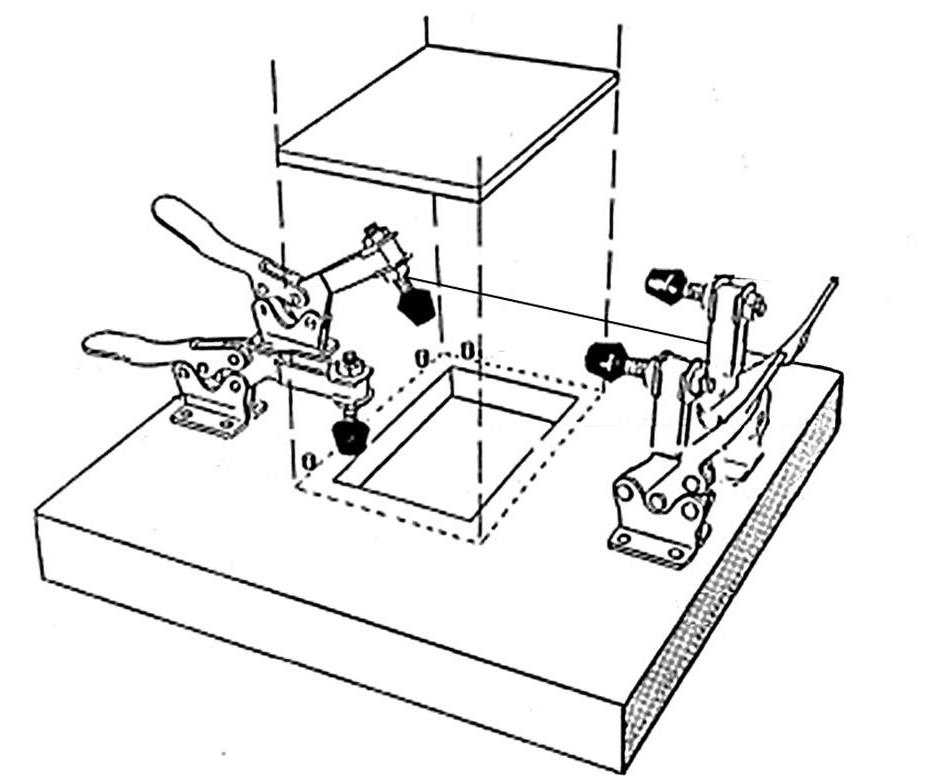
Fig. 1: Specimen support plate with rectangular hole for impacting (ASTM D 7136). Source (all photos): Dan Adams
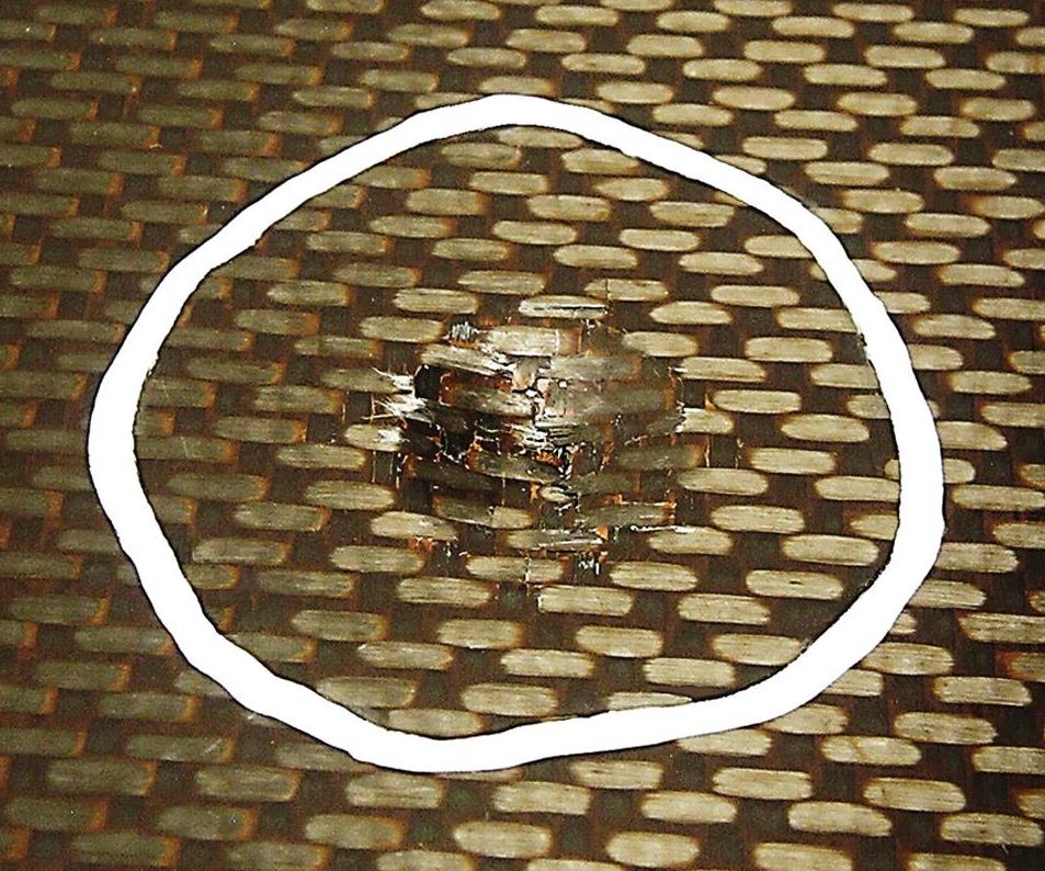
FIG 2a: Impact damage produced in woven carbon/epoxy composite specimen: Visual impact damage and outline of C-scan damage area (see also next photo)
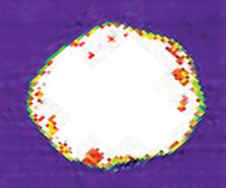
Fig 2b: The impact damage shown in Fig 2a in a woven carbon/epoxy composite specimen is shown here in this ultrasonic C-scan image of the internal damage area.


An important consideration for many composite structures, damage assessment targets two primary components: damage resistance and damage tolerance. Damage resistance refers to
the ability of a composite laminate or structure to resist damage formation. Of particular concern is damage produced due to impacts, which may cause extensive internal damage that is difficult to detect by visual inspection. Because the types and extent of damage produced by an impact depend on the layup and thick- ness of the laminate, as well as the material used, damage resistance is considered a structural rather than a material property.
In contrast, damage tolerance refers to the capability of an impact-damaged composite laminate or structure to maintain its strength and stiffness. The most common method of assessing damage tolerance is to perform an in-plane compression test using impacted composite specimens, referred to as Compression After Impact (CAI) testing. The focus here, however, will be on testing to assess the damage resistance of a composite laminate.
A damage resistance test has two phases: 1) impacting a composite specimen and 2) assessment of the damage produced. The most common procedure for specimen impact is the instrumented drop-weight impact test method, specified in ASTM D 71361. Although a variety of composite laminates may be tested, the use of [45°/90°/-45°/0°]ns quasi-isotropic laminates of 4- to 6-mm thickness is suggested for comparisons among different materials. The 100-mm by 150-mm specimen is clamped to a support plate that features a centrally located, 75-mm by 125-mm rectangular hole. This plate provides support for the specimen around its perimeter, but permits deflection of the specimen’s center section during impact (Fig. 1, at left). A 16-mm hemispherical tip impactor is specified. However, a different tip diameter and shape may be used to represent an identified impact threat for a particular application.
The impact energy, E, may be calculated based on the potential energy of the impacting mass, m, from the equation
E = m g h,
where h is the drop height and g is the gravitational constant (9.8 m/sec2). Alternatively, the impact energy may be calculated based on the kinetic energy at the point of impact using the equation
E = 1⁄2 m v2,
where v is the impactor velocity just prior to specimen contact. The use of kinetic energy in the second equation is typically considered more accurate, because friction as the weight is dropped results in less impact energy than that calculated using the potential energy expression in the first equation. But when an accurate measurement of the impactor velocity at impact is not available, the potential energy expression is considered acceptable.
The impact energy and the resulting level of impact damage are determined based on the purpose for testing. For material comparisons, ASTM D 7136 specifies a value of impact energy per specimen thickness of 6.7 J/mm to produce visual damage in the central region of the specimen. To identify the impact energy associated with barely visible impact damage (BVID), however, a series of impacts typically are performed with increasing impact energy, produced by increasing the drop height of the impactor.
A less commonly used method of damage resistance testing is the quasi-static indentation test, during which an indenter of the desired size and shape is pressed into the panel using a mechanical testing machine. ASTM D 62642 specifies the use of a 150-mm by 150-mm specimen and two support conditions: 1) edge supported on a support plate with a 125-mm diameter circular cutout and 2) rigidly backed on a solid support plate. Because neither of these support conditions are the same as the rectangular cutout specified for drop-weight impacting in ASTM D 7136, they would not be expected to produce the same damage formations. But research studies have shown that if the same specimens and support condi- tions are used, comparable damage formations will be produced when the maximum force applied during indentation testing is the same as the peak force produced during drop-weight impacting3.
The extent of the damage produced in the composite specimen can be measured by nondestructive and destructive inspection methods. Note, however, that if impacted specimens are to be used for follow-on damage tolerance testing, only nondestructive methods should be used.
Common nondestructive measures of impact damage include surface indentation depth, measured with a depth gage micrometer. ASTM D 7136 specifies that this depth measurement be made immediately after specimen impact because the indentation depth might decrease over time. In some cases, an additional depth measurement is made from one to seven days afterward, to better assess the indentation that would be present during visual inspection in service. Unfortunately, considerable scatter is common in indentation depth measurement data and, therefore, they are of limited use. Measurement of visually observable surface damage, such as cracks, also can provide a simple damage metric and can be used to establish impact energy levels associated with BVID (Fig. 2a). But the most commonly used damage metric is the planar damage area, produced using ultrasonic C-scan inspection. Using the pulse-echo method, an ultrasonic pulse is sent through the specimen thickness. The pulse reflects back to the probe when it reaches either the panel’s back surface or internal damage, such as delaminations. The planar damage area thus can be identified and measured, as the probe scans the region of impact (Fig. 2b).
If destructive inspection is permissible, specimens can be sectioned through the impacted region, polished and examined using optical microscopy. Additionally, the impacted region may be cut from the larger specimen and X-ray microCT scanned to produce a three-dimensional image of the internal damage. Because both methods are more time-consuming and costly, they tend to be used less frequently.
References
1ASTM D7136-15, “Measuring the Damage Resistance of a Fiber-Reinforced Polymer Matrix Composite to a Drop-Weight Impact Event,” ASTM International (W. Conshohocken, PA, US), 2015 (originally published 2005).
2ASTM D6264-12, “Measuring the Damage Resistance of a Fiber-Reinforced Polymer Matrix Composite to a Concentrated Quasi-Static Indentation Force,” ASTM International (W. Conshohocken, PA, US), 2012 (originally published 1998).
3A.T. Nettles and M.J. Douglas, “A Comparison of Quasi-Static Indentation to Low-Velocity Impact,” NASA Technical Report TP-2000-210481, 2000.


.jpg;maxWidth=300;quality=90;format=webp)
Read Next

CW’s 2024 Top Shops survey offers new approach to benchmarking
Respondents that complete the survey by April 30, 2024, have the chance to be recognized as an honoree.
Read More
From the CW Archives: The tale of the thermoplastic cryotank
In 2006, guest columnist Bob Hartunian related the story of his efforts two decades prior, while at McDonnell Douglas, to develop a thermoplastic composite crytank for hydrogen storage. He learned a lot of lessons.
Read More
Composites end markets: Energy (2024)
Composites are used widely in oil/gas, wind and other renewable energy applications. Despite market challenges, growth potential and innovation for composites continue.
Read More