
Concert hall composites: Acoustic alchemy
Massive composite acoustic structures will reflect and diffuse sound to heighten audio quality in a new high-profile performance space.
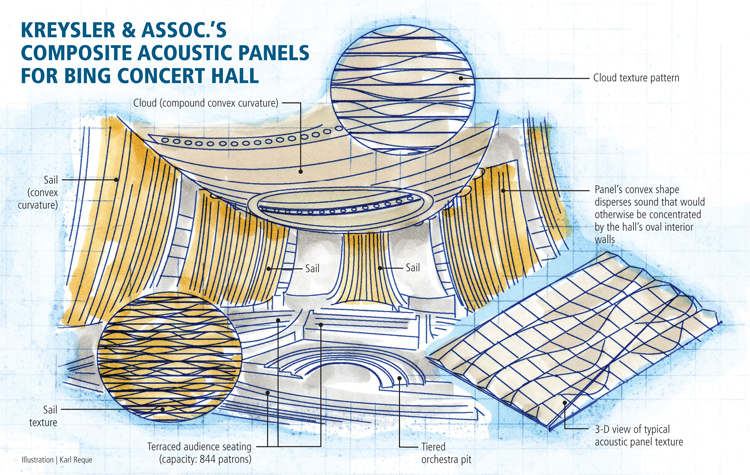
Kreysler and Assoc. Composite Acoustic Panels for Bing Concert Hall. Illustration: Karl Reque
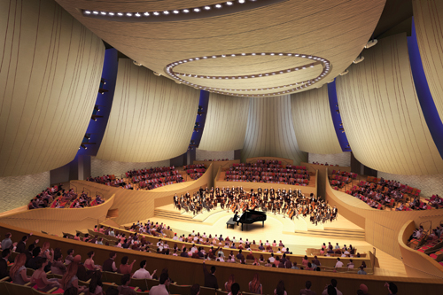
More than 120 composite panels combine to form the sail and cloud structures represented in this artist’s rendering of the interior of the Bing Concert Hall at Stanford University. The panels are being used to enhance acoustics in the hall, which is expected to open in 2013. Source: Ennead Architects; Rendering by Crystal CG
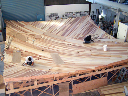
Mid-construction photo of the mold for one of the sail panels. Three layers of thin plywood strips were nailed to a waffle subframe to form the curvature. Source: Kreysler and Assoc.
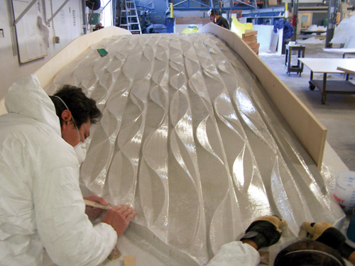
One of the CNC-machined patterns is prepared to have a mold face made from it. Workers are installing flanges and doing final hand finishing. Source: Kreysler and Assoc.
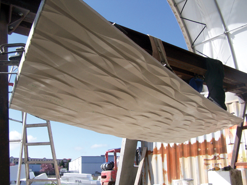
One of the first complete cloud panels is shown here, suspended in the sandblasting area at Kreysler & Assoc.’s manufacturing facility. Source: Kreysler and Assoc.


Engineering Challenge:
Efficiently and economically design and manufacture large (up to 50-ft/15.2m long), complex composite acoustic structures that can be suspended from the walls and ceiling of a new concert hall.
Design Solution:
With the aid of 3-D modeling software, the large structures are divided into 120 manageable subsections that can be molded on a very small number of tools.


Concert hall design is all about acoustics — filling the space with exceptional sound that draws the audience in to an intimate experience with the performer. The 844-seat Bing Concert Hall, currently under construction at the gateway of Stanford University (Stanford, Calif.), is no exception.
“From the very beginning, it was incredibly clear that we were to make the acoustics the absolute best we could make them,” says Richard Olcott, design partner, Ennead Architects (New York, N.Y.). “That was the number one goal.” To that end, well-known acoustician Yasuhisa Toyota (Nagata Acoustics, Los Angeles, Calif.) provided the acoustic design for the hall and was the driving force behind much of the final architectural design.
The hall’s oval space features a terraced seating configuration. Although the audience and seats tend to absorb sound, the dividing walls used in the terraced design actually add reflective acoustic properties within the space. But the wide range of performances and performers the hall will accommodate within its relatively small space — from small chamber music ensembles to full orchestras with chorus — posed an acoustical challenge, according to Toyota.
One critical adjustment made in the early building design was an increase in the hall’s ceiling height. At 47-ft/14m high, the ceiling is nearly as high as that in concert halls triple its overall size. Olcott explains that the ceiling design is “the ideal height to create a longer reverberation, a richer, fuller sound.”
Critical to optimal sound in the hall are dramatic acoustic panels, a combination of a glass fiber-reinforced polyester skin on top of steel-reinforced concrete, that will be mounted to the walls (called sails) and ceiling (dubbed the cloud). Designed and manufactured by architectural composite fabricator Kreysler and Assoc. (American Canyon, Calif.), the panels cover most of the performance hall’s interior walls and ceiling. Their convex shapes counter the sound concentration that could result from the hall’s concave shape. The panels disperse the sound to create a richer quality by enabling the audience to hear sounds coming from more than one direction.
Kreysler is building 120 unique subpanels from which the sails and the overhead cloud structure will be assembled. Each must conform to the precise requirements of the acoustician, who used scale models to detect and eliminate detrimental echoes and employed additional tools that facilitate the study of room shape, which directly relates to sound distribution in the audience area. The keys to achieving the right result are the shape, density and surface finish of the panels.
“The heavier the reflecting material is, the wider the frequency range can be reflected from the surface — especially low frequencies,” says Toyota. To achieve the required effect in the Bing hall, Toyota specified a relatively high density for the composite panels — 12 lb/ft2 for the sails and 20 lb/ ft2 for the cloud. “A rough surface finish was requested in order to diffuse/absorb very high frequencies,” he adds.
Optimizing the sound
“Generally speaking, software played some role in nearly every part of the project,” says Joshua Zabel, director of digital fabrication at Kreysler. “While we were working with the architect, acoustician and engineer, 3-D modeling software was a useful communication tool for illustrating ideas about the complex geometry as the design evolved,” he explains. “For us, the software helped communicate ways in which making small changes to the geometry of the sails or the cloud could have effects on fabrication efficiency, and therefore cost.”
Kreysler uses RHINO software produced by Robert McNeel and Assoc. (Seattle, Wash.) for the majority of modeling tasks. “There are various plug-ins for RHINO that have played an important role in the project, including Grasshopper, which is a parametric design tool with many uses, and RhinoNest, which allows us to efficiently pack a collection of 2-D shapes into stock material,” explains Zabel. Also, PowerMILL software from Delcam (Birmingham, U.K.) is generating the tool paths for the CNC machines.
The general contractor at Turner Construction (New York, N.Y.) is currently managing a building information model (BIM) in Navisworks (Autodesk Inc., San Rafael, Calif.), which incorporates the 3-D work of all the subcontractors. “It helps identify and resolve spatial conflicts between trades,” explains Zabel. “It is a complete digital model of all aspects of the building. In the case of both the sails and the cloud, this allows us to build a digital model of what we intend to fabricate, and the structural steel fabricator can do the same. These come together in the BIM model and allow both of us to ensure that the connections from one system to the next will line up predictably.”
“In many cases, the computer model is used directly by the CNC machines for fabrication, and after fabrication, the same CAD models are used to check the dimensions of the fabricated parts as a quality-control measure,” he adds.
Setting the sails
Kreysler is making nine sails — four for each side and one for the end of the hall. “Each sail has a unique curvature, orientation and shape,” explains Serge Labesque, Kreysler’s production engineer, adding that finding an economically viable production solution was one of the biggest challenges.
Each sail is assembled from four to seven separate panels that are bolted together via 3-D trusses that, when put together, create a spaceframe. This frame is then connected to the steel structure of the building.
“We entertained the idea of manufacturing the individual panels using smaller molds, but ultimately we decided to use one large mold to produce all of the sections for each sail at once in order to ensure that the panels would align as well as possible,” says Labesque.
The molds are constructed of wood overlaid with glass fiber-reinforced polymer (GFRP). “There will be a total of five molds for the sails,” says Labesque. “One is narrow, measuring approximately 10 ft by 45 ft [3m by 13.7m], while the others vary from 40 ft by 40 ft [12m by 12m] to more than 50 ft by 50 ft [15.2m by 15.2m].”
“The shape and structure of these molds is being designed in the computer with the idea of a ‘kit-of-parts,’” explains Zabel. “The wood for the molds will be cut out and labeled on a CNC machine in a way that it can be easily assembled in the shop and be the correct curvature of the sails without the need for any special measuring or fabrication equipment.”
To produce the necessary mass, Kreysler adds reinforced concrete behind a 0.1875-inch/5-mm thick GFRP skin. After the mold is prepared, multiple plies of 1.5-oz chopped strand mat from Composites One (Arlington Heights, Ill.) are wet out with a fire-retardant Norsodyne polyester from CCP Composites (formerly Cook Composites & Polymers, Kansas City, Mo.).
When the FRP skin is cured, says Labesque, threaded metal studs are placed 1-ft (0.3m) on-center. They hold the steel reinforcing mesh that will run through the center of the concrete and, when the concrete is poured into the mold, they are used to gauge the pour thickness. Together with an epoxy adhesive, they also secure the concrete to the skin. Flex anchors extend from the FRP above the surface of the concrete and are welded to the steel structure.
“Once the sail has been fabricated in the mold, the pre-assembled steel space frame is placed over the back and welded in place,” adds Zabel. “The sail then comes out of the mold in approximately 8-ft [2.4m] wide sections with the space frame attached.”
The finished sails vary in size from 28 ft by 29 ft (8.5m by 8.8m) to 43 ft by 51 ft (13m by 15.5m).
Crafting a cloud
The overhead 60-ft by 127-ft (18m by 39m) cloud structure comprises 80 individual panels that, unlike the sails, form a compound curve. Although the curvature is constant, the panels vary in size and the penetrations and other prominent features differ from panel to panel, making each unique. Also unique is the rippled pattern designed into its surface. Its ridges diffuse sound, scattering it in many directions. Because a ridge pattern with fixed intervals could cause undesirable echoes, the surface variation is random. In fact, two different patterns of articulation are being used for the cloud panel faces. Dearticulation on the surface is 0.75 inch/19 mm, resulting in an overall panel thickness ranging from 2 inches to 2.75 inches (51 mm to 70 mm). “During the design process, the articulation changed many times due to architectural and acoustic considerations, and we had to be able to adjust to each change,” says Labesque, noting that the final surface pattern bears little resemblance to that in the original architectural design.
“The curvature and articulation of the cloud were built into the 3-D CAD model, which was used by our CNC machines to cut the patterns for the cloud panels,” explains Zabel. “The 3-D model was used directly in the fabrication process.” Despite this complexity, only two molds, made of GFRP, were necessary for the cloud panels.
Although the cloud panels are manufactured using the same materials and process as the sails, “the steel structure is different and the mass of concrete is very different,” Labesque says. “The concrete layer in the sail panels is approximately 1 inch [25.4 mm] thick, while it’s closer to 2 inches [50.8 mm] thick in the cloud panels.”
Kreysler designed the steel structure that supports the cloud panels, explains Labesque. “The cloud panels are suspended by connections at 4-ft [1.2m] on-center.”
Awaiting the music
Manufacturing each sail takes about a week. The sail and cloud sections will be shipped individually to the job site via tractor trailer. The installed sails will be coated with BASWAphon from BASWA Acoustic (Willoughby, Ohio), producing a thick, hand-troweled plaster effect that will yield the desired combination of sound absorption and sound reflection. Construction of the hall is due to be complete in 2012, with the first performance set for 2013.


.jpg;maxWidth=300;quality=90;format=webp)


Related Content

Sulapac introduces Sulapac Flow 1.7 to replace PLA, ABS and PP in FDM, FGF
Available as filament and granules for extrusion, new wood composite matches properties yet is compostable, eliminates microplastics and reduces carbon footprint.
Read More
Plant tour: Joby Aviation, Marina, Calif., U.S.
As the advanced air mobility market begins to take shape, market leader Joby Aviation works to industrialize composites manufacturing for its first-generation, composites-intensive, all-electric air taxi.
Read More
The making of carbon fiber
A look at the process by which precursor becomes carbon fiber through a careful (and mostly proprietary) manipulation of temperature and tension.
Read More
Materials & Processes: Fibers for composites
The structural properties of composite materials are derived primarily from the fiber reinforcement. Fiber types, their manufacture, their uses and the end-market applications in which they find most use are described.
Read MoreRead Next

Composites end markets: Energy (2024)
Composites are used widely in oil/gas, wind and other renewable energy applications. Despite market challenges, growth potential and innovation for composites continue.
Read More
From the CW Archives: The tale of the thermoplastic cryotank
In 2006, guest columnist Bob Hartunian related the story of his efforts two decades prior, while at McDonnell Douglas, to develop a thermoplastic composite crytank for hydrogen storage. He learned a lot of lessons.
Read More
CW’s 2024 Top Shops survey offers new approach to benchmarking
Respondents that complete the survey by April 30, 2024, have the chance to be recognized as an honoree.
Read More