
Composite wing key to high-speed stability
First mass-produced CFRP wing helps supercar achieve downforce and lateral acceleration values superior to many GT racing cars.

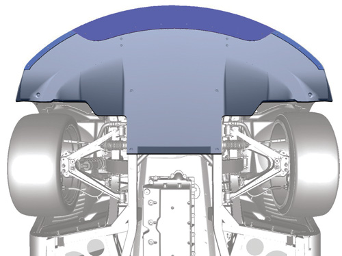
For track racing, the street-version splitter's center strip is replaced with the VHMWPE track extension (shown in dark blue), which extends the splitter to its full profile, 3.2 inches/80 mm beyond the car’s nose. Source: Chrysler LLC
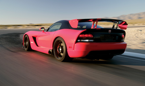
The large CFRP rear wing on this street-legal 2008 Dodge Viper ACR supercar contributes 60 percent of its 7:1 downforce-to-drag ratio, giving the car high-speed steering/cornering stability superior to many GT racing cars. The other 40 percent is contributed by a front splitter and dive planes (see sidebar, at bottom of this page). The chart below illustrates the extent to which the aero package counteracts natural lift. Source: Chrysler LLC
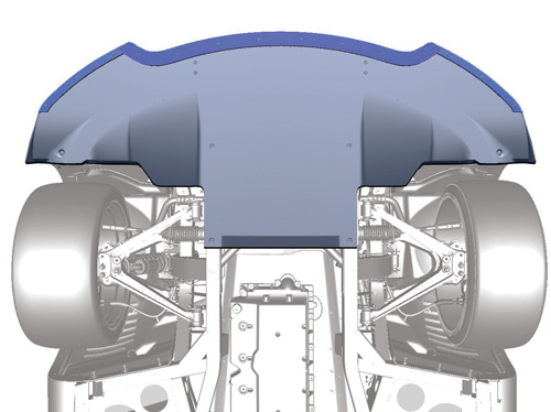
The ACR’s unique front splitter has more surface area than the rear wing and features seven diffuser surfaces, each tuned to create downforce under the front of the car to balance downforce exerted by the rear wing. For the configuration above, designed for street driving, VHMWPE rub strips (top, shown in dark blue) are mechanically fastened to the splitter to protect the panel from damage. Source: Chrysler LLC
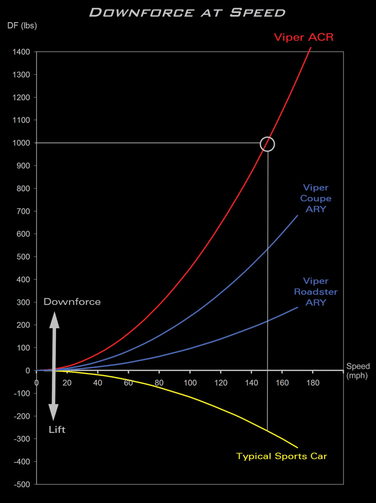
This chart illustrates the extent to which the aero package counteracts natural lift. The "ACR" curves shows the optimum benefit frm the package illustrated in this article. The blue “ARY” curves show downforce achieved by Coupe and Roadster packages, which use a shorter rear wing. Source: Chrysler LLC
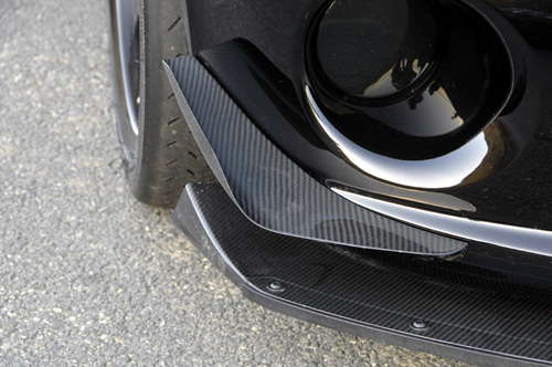
To generate sufficient front downforce to balance that from the rear wing, the Viper ACR is fitted with a front splitter under the bumper (shown here in “fanged” street mode) and two dive planes (a/k/a canards or fins) attached under the headlamps. Source: Drew Phillips
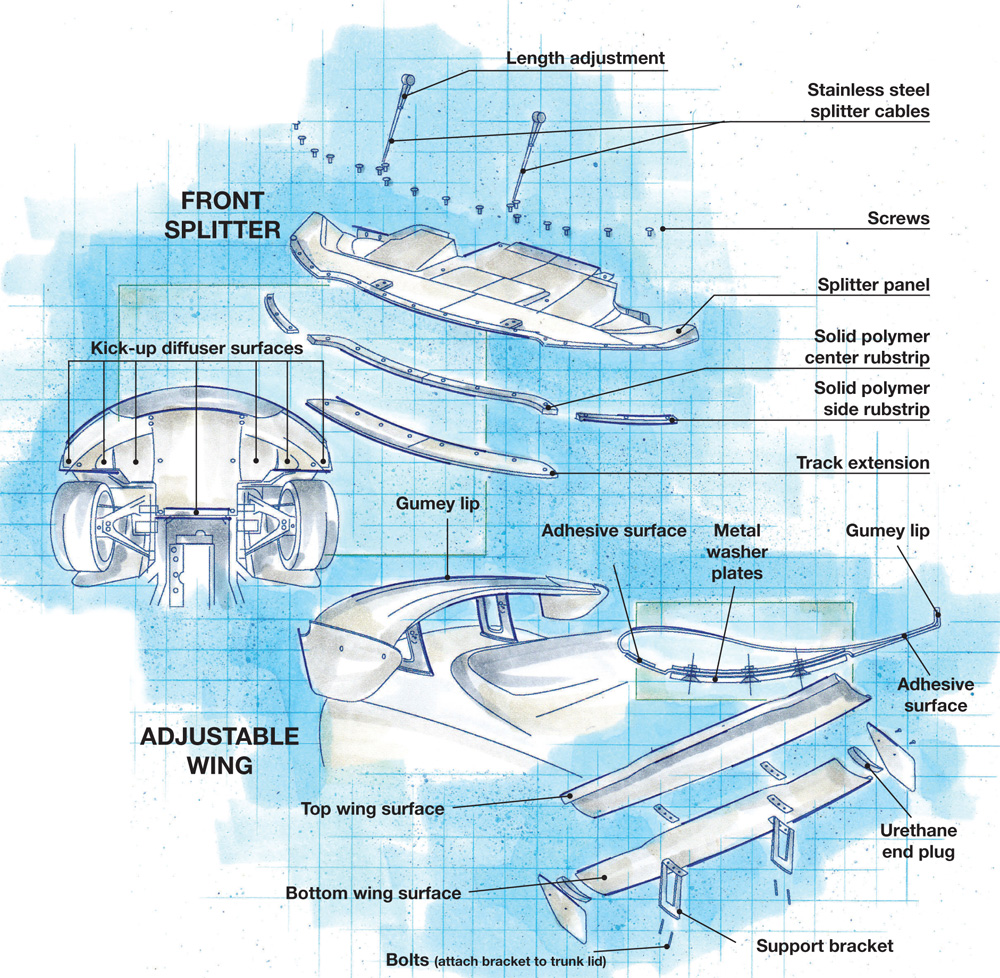
Illustration: Karl Reque
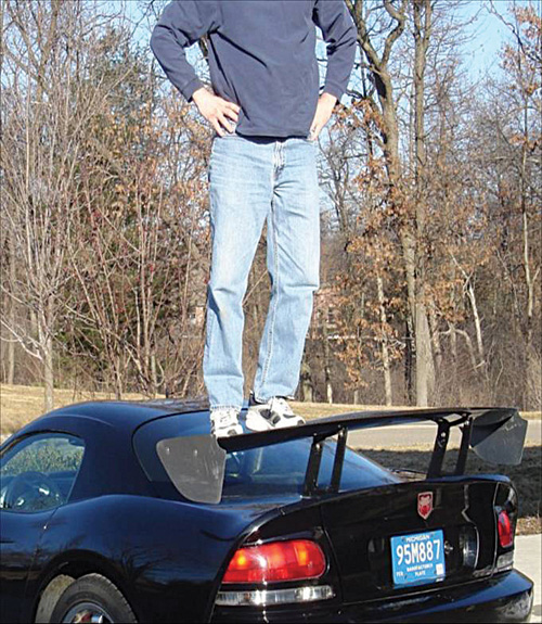
Although each half-shell of the Viper ACR’s rear wing comprises only four layers of epoxy/carbon fiber weave, without the support of ribbing or core, it offers — as this photo clearly demonstrates — very high bending stiffness. Source: Chrysler LLC
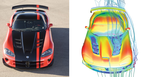
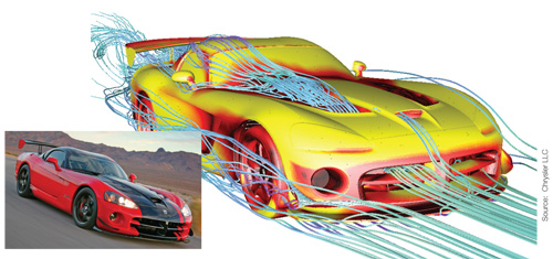
This CFD profile of the top of the Viper ACR shows how airstreams are managed along the driver’s side of the vehicle. Front air scoops feed cooling airstreams over the ACR’s engine, then up and over the windshield and roof where they continue a smooth flow path under the rear wing, creating high downforce. Also visible from this angle are airstreams deflected under the front of the vehicle by the front splitter as well as the driver-side vortex stream produced by the left dive plane. Soruce: Chrysler LLC
In track mode (with track extension installed on the front splitter) the Viper ACR exhibits its best possible front/rear downforce balance, enabling it to corner at speeds high enough to clock the fastest 2008 Nürburgring lap time, beating out much more exotic and costly supercars. A CFD plot (right), shows how the splitter and dive planes deflect airflow around the front end — the latter creating trailing air vortices that draw air from the front wheel wells as it passes by. Source: Chrysler LLC


Design Results
- Carbon fiber-reinforced rear wing increases supercar handling stability at speeds up to 150 mph/245 kmh.
- Companion front splitter and dive planes produce balanced 7:1 downforce-to-drag ratio.
- Aerodynamic components contribute to vehicle aesthetics without adding significant mass, restricting functionality or violating federal bumper laws.
One of the most important challenges engineers face when they design cars for track speeds in excess of 150 mph/245 kmh is finding a way to generate sufficient aerodynamic downforce to counter natural lift at high speeds. As the term implies, downforce pushes down harder on a vehicle the faster it travels, increasing tire traction, which enables the driver to maintain steering stability. Keeping all four wheels on the ground also increases safety because the margin for error at such speeds is very small.


Although race cars have long been designed to take advantage of downforce, most street-legal sports cars aren’t designed that way. At high speeds, they tend to produce lift, with a resulting reduction in stability. Such was the case when Chrysler LLC’s (Auburn Hills, Mich.) Street & Racing Technology (SRT) team began working on functional upgrades for the 2008 ACR (American Club Racer) model of the Dodge Viper. “Our main design goal was to create racing aerodynamics in a production sports car, which had never been done before, so there were no real benchmarks we could draw upon,” says Mike Shinedling, Viper program manager in Chrysler’s SRT Performance Group. “Given our functional objective of faster lap times, we focused on generating aerodynamic downforce to allow the car to achieve higher cornering speeds.”
Looking forward and looking back
In the absence of production-car benchmarks, the team looked at purpose-built race cars, such as the Viper Competition Coupe and Viper GTSR, on whose racing programs several ACR team members had worked. The 1969 Dodge Daytona sports car also provided inspiration. Considered to be the grandfather of the ACR, because it, too, achieved a major paradigm shift in production-car aerodynamics, the Daytona’s massive rear wing produced an aerodynamic advantage that enabled it to dominate professional racing back when stock cars were still based on production vehicles.
Next, the team did an extensive study of wing profiles. More than 200 simulations were performed to find the optimal airfoil section. Some profiles were aerodynamically efficient — defined as (negative) lift over drag where negative lift/downforce is the goal — but not feasible because their shapes did not allow for molding and assembly within an automotive-production process. Shinedling recalls, “Once we settled on a baseline 2-D airfoil, we swept it in the third dimension. We used digital airstreams generated around the car roofline to determine the angle of attack at each point along the wing. The wing is not a simple constant section: Its shape morphs and pitches from one side of the car to the other.”
Most of the work was done with computational fluid dynamics (CFD) modeling, using Exa Corp.’s (Burlington, Mass.) PowerFLOW software. The wing’s trailing edge was largely developed in Chrysler’s state-of-the-art Aero-Acoustic Wind Tunnel. “We looked at different trailing-edge shapes, including unusual sawtooth patterns before we ended up with our sweeping ‘gurney lip,’ which rises in the center and relaxes at the outboard ends. This gave us the best drag efficiency without sacrificing downforce,” adds Shinedling. (Gurney is an aerodynamic feature that trips or kicks up the airflow at the rear edge of the wing, see drawing detail at right.)
The team’s greatest challenge was tuning the aerodynamics when a wing design was selected — engineers spent 1,300 hours between the wind tunnel, CFD simulations and the racetrack. Along the way, they were surprised by how well the wing worked. Although the initial target was 700 lb/318 kg of downforce at 150 mph/245 kmh, the first simulations came in at more than 900 lb/408 kg, so the team decided to stretch and set a new target of 1,000 lb/454 kg.
Early success with the rear wing, however, created a new problem: The wing produced so much rear downforce that, to properly balance the car, it was necessary to generate strong front downforce to counteract aerodynamic pitch. That, Shinedling notes, is very difficult in a street-legal passenger car because of driveability issues and the fact that many existing front-downforce solutions extend outward from the bottom front and side of the vehicle in violation of federal bumper laws. The problem was solved by adding variable-geometry front splitter and dive planes, which, in the final design, contribute roughly 40 percent of the vehicle’s total downforce. (See the sidebar “Front-end add-ons balance aerodynamics,” at the bottom of this page.)
With such aggressive downforce targets, experience told the team that a carbon fiber-reinforced polymer (CFRP) was the only material form capable of meeting performance and weight targets — the latter of particular importance because a heavy wing attached to the vehicle’s rear liftgate would reduce access to functional rear storage and would also countermand a goal of reducing vehicle mass by 80 lb/36 kg. Other material/process options didn’t measure up: The geometry limitations of extruded aluminum couldn’t meet wing aerodynamic targets; blow-molded thermoplastics wouldn’t survive downforce loads at high speeds; and sheet molding compound (SMC) was too heavy and didn’t hit high bending-stiffness targets. The final CFRP design, at 72-inches/183-mm wide by 8-inches/20-mm deep, weighs only 7.5 lb/3.4 kg — 50 to 80 percent less than if it had been produced via the aluminum, thermoplastic or SMC options.
Adding to program challenges, the ACR team wanted two aesthetic options for the wing: a 100-percent visible, carbon-weave version with clear topcoat (also used for the splitter and dive planes) and a painted version. The aesthetic needs of each option would require different material combinations and unique kitting for part layup. Another challenge posed by the clearcoated wing was to provide sufficient UV-protection. UV damage isn’t worrisome for short-lived, purpose-built race cars with interchangeable parts, but for production cars with long-term aesthetic and performance warranties, it could be a nightmare.
Translating design to production capability
Early in the program, the ACR team tasked Prefix Corp. (Rochester Hills, Mich.), the Tier 1 supplier, and Plasan Carbon Composites (Bennington, Vt.), the component manufacturer, with finding effective solutions.
To build the structurally and aesthetically demanding wing, Plasan worked with Akzo Nobel (Amsterdam, The Netherlands) on paint and material development. Together, the supply team produced a family of low-VOC/fast-cure epoxy resins formulated to ensure long-term high visual impact by means of an integrated, patented UV stabilizer/carrier as well as a UV-resistant clearcoat that met Chrysler’s objectives. The UV package is considered among the most important program breakthroughs. Plasan’s epoxy cure averages just 10 minutes per part in the autoclave cure cycle.
Advanced Composites Group (ACG, Heanor, Derbyshire, U.K.) provided the exposed-weave prepreg for the clearcoated wings. Engineered Textile Solutions (ETS, Darien, Conn.) supplied unidirectional carbon prepregs for the painted wings, which formed a specialized Class A outer layer meant to resolve the team’s previous problems with fiber read-through. High-tensile-strength woven fabrics from Hankuk Fiber Co. Ltd. (Miryang Kyungnam, South Korea) were used in the underlayers of both wing styles to resist high downforce loads at top speeds. The high strength and bending stiffness of the CFRP material eliminates the need for support ribs, another source of potential read-through.
Considered to be the first mass-produced CFRP wing in the auto industry, the two-piece, hollow bonded structure is produced by hand layup and vacuum bag/autoclave cure and finished with inner end plugs molded of urethane by Prefix Corp. A layup pattern of 0/90/0/90 is used to produce each half shell of the wing. Hardware is inserted during layup. Kits are cut using an automated Eastman Machine (Buffalo, N.Y.) cutting table. A high-temperature, fast-cure bonding adhesive developed by Ashland Inc. (Dublin, Ohio.) is used to join both wing sections and the end plugs. The total wing production time is one hour.
Unique assembly and holding fixtures were required to achieve the wing’s high-strength bonding and high degree of edge finishing. The wing’s complex cross section and plan view sweeps are edge-machined via an innovative 5-axis robot (supplied by KMT, Detroit, Mich.). Its router head is capable of producing very tight, small radii and complex slope changes at high spindle loads because the precision aerodynamic profile will not permit more than 0.25-mm/0.01-inch surface variation across the part.
The clear wing required exacting production techniques to meet extremely challenging quality-control standards so there were no loose weaves and no fiber bundles were twisted or out of place in the finished part.
“Thanks to a high degree of supply-chain collaboration,” notes Gary Lownsdale, engineering manager at Plasan, “this program went from surface drawings to volume production in less than 12 months, and we pulled our first parts from the production process in less than six months. The short lead time — achieved thanks to simultaneous design of part, tool and process using math data — allowed Chrysler additional aerodynamic development time via CFD and wind tunnel.” Interestingly, Lownsdale worked on the aerodynamics package for the previously mentioned 1969 Dodge Daytona early in his career at Chrysler.
The wing’s low-cost tooling was $300,000 (USD) less than tooling for a lower performing blow-molded wing. This unique tooling process allows multiple versions of the wing to be processed on one tool: the high-performance clearcoated and painted ACR wings, as well as optional “aero-package” wings for the standard Viper Coupe and Roadster that are 12 inches/31 cm shorter. “We didn’t make any design compromises on the ACR wing to also accommodate the shorter wings,” explains Plasan’s Robert Murch, R&D engineer. “The tooling was designed to be flexible enough to allow different trailing-edge features and different cross-car trim widths without needing any special inserts. The layup process and robotic trimming dictate the final wing profile, and trimming and bonding fixtures have removable sections that allow production of either long or short wings on the same secondary tooling.”
Cornering in a class of its own
Chrysler reports that the aero package on all three Viper models (ACR, Coupe and Roadster) have a 30 percent take rate. On the ACR, the wing is fitted with a two-piece stanchion with a pivot and sets of holes that allow the wing to be adjusted to accommodate different driving styles and track conditions. With an aerodynamic efficiency gain of 7:1 (downforce to drag), the ACR achieves performance that, in some cases, is superior to that of professional GT racing cars. At low speeds (50 to 60 mph/81 to 97 kmh), it corners with lateral acceleration of 1.13 Gs — a very high number even for a sports car. But at high speeds (140 to 150 mph/225 to 245 kmh), it can sustain cornering loads of 1.50 Gs in high-speed turns. “These are numbers only achievable with racing aerodynamics,” Shinedling points out. In fact, the Viper ACR (MSRP $98,110 USD) turned in 2008’s fastest Nürburgring lap times, beating out (in order of finish) three much more expensive supercars: a Maserati MC12 (MSRP $974,800), a Pagani Zonda (MSRP $741,000) and a Ferrari Enzo (MSRP $643,330).


.jpg;maxWidth=300;quality=90;format=webp)

Related Content

Cycling forward with bike frame materials and processes
Fine-tuning of conventional materials and processes characterizes today’s CFRP bicycle frame manufacturing, whether in the large factories of Asia or at reshored facilities in North America and Europe. Thermoplastic resins and automated processes are on the horizon, though likely years away from high-volume production levels.
Read More
Carbon fiber in pressure vessels for hydrogen
The emerging H2 economy drives tank development for aircraft, ships and gas transport.
Read More
Cryo-compressed hydrogen, the best solution for storage and refueling stations?
Cryomotive’s CRYOGAS solution claims the highest storage density, lowest refueling cost and widest operating range without H2 losses while using one-fifth the carbon fiber required in compressed gas tanks.
Read More
Materials & Processes: Fibers for composites
The structural properties of composite materials are derived primarily from the fiber reinforcement. Fiber types, their manufacture, their uses and the end-market applications in which they find most use are described.
Read MoreRead Next

Carbon Fiber Goes Mainstream Automotive
DaimlerChrysler breaks new ground with carbon fiber SMC components in 2003 Viper.
Read More
Composites end markets: Energy (2024)
Composites are used widely in oil/gas, wind and other renewable energy applications. Despite market challenges, growth potential and innovation for composites continue.
Read More
From the CW Archives: The tale of the thermoplastic cryotank
In 2006, guest columnist Bob Hartunian related the story of his efforts two decades prior, while at McDonnell Douglas, to develop a thermoplastic composite crytank for hydrogen storage. He learned a lot of lessons.
Read More