
Composite rib structure for Airbus A380 vertical tail
Fabricator exceeds Airbus performance requirements with hand layed rib truss structure for A380.


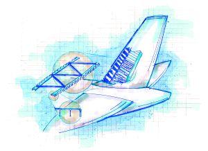
Source: Karl Reque, IllustrationSchematic of the composite rib structure in the A380 vertical tail. Made with traditional hand layup methods, they exceed the weight goal by more than 25 percent, at an acceptable cost.
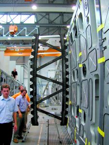
Source: HITCOThe rib truss is shown being integrated with assembly fixtures for the A380's vertical tail plain.
The world's biggest commercial airplane, due to make its first flight early next year, already has made a huge impact on the composites industry. Each Airbus A380 will carry 30 metric tonnes/66,000 lb of structural composites, about 16 percent of the total airframe weight of 170 metric tonnes. HPC has reported previously on the A380's development and overall design (see HPC September 2002, p. 14) and, since part construction began in earnest, also has spotlighted a trend, fostered by Airbus, toward the use of automation and closed-mold methods to meet cost constraints. Recent articles have examined an innovative use of resin film infusion in the molding of the rear pressure bulkhead (HPC May 2003, p. 45) and a unique prepreg pultrusion process used to fabricate structural support profiles for the aircraft's upper deck (HPC September 2003, p. 36).
As part of the A380's material down-select process, Airbus has emphasized careful selection of the most appropriate materials and most cost-effective manufacturing processes for each structural application. In the case of the rib truss structures for the A380's vertical tail plane (VTP), HITCO Carbon Composites Inc. (Gardena, Calif., U.S.A.), was able to show that hand layup of carbon/ epoxy prepreg was the preferred option. With a combination of pre-production design planning and unique tooling design, HITCO's rib trusses made with traditional methods beat Airbus' weight goal by more than 25 percent, at an acceptable cost. Recently, HPC had the opportunity to visit HITCO's facility to see the parts being manufactured.


Key part of a huge structure
The A380's tail, at 14m/45 ft high and 13m/42 ft long at the root, will be the largest commercial aircraft tail in the air. The highly loaded structure incorporates a number of composite components, including pultruded profiles, resin-infused spars and automatic tape layed outer skins. HITCO's carbon/epoxy rib trusses form the primary internal structure that supports the tail skins in the forward, lower one-third of the VTP, just behind the leading edge. Seven individual trusses make up one ship set, each one with different dimensions and curvature, which match the tail's progressively narrower leading edge as it rises in height.
"The design is essentially a simple truss, like that used for a roof or a bridge," says HITCO vice president of engineering Steven Seid Jr. "Two inner mold line (IML) curved edge profiles are connected by five rectangular struts in a transverse pattern."
The approximately 3.1m/10 ft long and 1.5m/5 ft wide trusses are curved in plan view to match the IML of the tail's left and right skins, "essentially the IML of the tail's airfoil," says Seid. Viewed edge-on, the curved outer profiles, termed "LUs" by HITCO, are L-shaped, with two additional upstanding legs or ribs. The short dimension of the "L" is shimmed and bolted to the IML of the tail skins. Five struts connect the LUs to form the truss shape. Although each of the seven trusses has different dimensions, all are similarly connected with five struts.
The trusses were designed by HITCO, with the assistance of Enabling Technologies Consulting Engineers Ltd. (ETCEL, Newport, Isle of Wight, U.K.), a structural analysis and design firm. Airbus supplied interface control drawings, which specified how the parts had to integrate with the rest of the VTP, as well as the load requirements. HITCO and ETCEL used CATIA (v. 4.2.4) from Dassault Systemes (Woodland Park, Calif., U.S.A.) to create the two-dimensional part drawings and employed NASTRAN software for the finite element analysis (FEA) modeling.
"HITCO colocated an engineer at the Airbus facility in Hamburg for nine months while the design details were worked out among HITCO, ETCEL and Airbus," notes Seid. "We put together a pre-production study showing several different part geometries, and were able to choose the one that provided the best performance at the lowest weight while, at the same time, posing the fewest manufacturing issues."
The trusses are designed to withstand the air loads imposed on the tail's OML surface. Loads are transferred from the skins and distributed into the stable truss, which resists buckling and torsional stresses. The principal design driver was weight, says Seid, and designers looked for innovative ways to achieve performance while driving down part mass. The open truss design, a classic in civil engineering, maximizes strength while minimizing needed material. Serrations machined into the outer edges of the LU profiles significantly lighten the part while allowing accessibility to fasteners for the skins. In a rather innovative twist, the rectangular struts that connect the LU profiles are hollow rather than solid, also saving weight.
"The design reduced the part weight by 26 percent while keeping the performance under design loads constant," explains Seid.
A hybrid manufacturing approach
With the part design in place, the challenge was to develop tooling that could accommodate the curved, upstanding legs that are integral to the LU profile, as well as the hollow struts.
Says Seid, "We investigated resin transfer molding [RTM], for the struts and LUs, but because of the tight schedule constraints, we chose modular layup tooling because it enabled faster production."
HITCO essentially took a hybrid tooling approach, specifying RTM-like matched metal tooling with an upper caul plate to produce the LU profiles, to ensure that final dimensional requirements were achieved. Tools were designed to allow for slight variations in the fiber areal weight (FAW) of the prepreg material. Seven Invar Nilo-36 tools, one for each of the seven LU components, were fabricated by Martinez and Turek (Rialto, Calif., U.S.A.). All of the tools were produced within a six-month period, a very aggressive tooling schedule for Invar material.
The LU tools consist of five primary metallic molds or details - one detail to define the OML of the part, three internal U-shaped mandrels that shape the LU's upstanding legs, and one base plate. Prepreg material is hand layed into the three mandrels and the OML detail. HITCO selected materials identical to those specified for the majority of the composite parts on the A380 - high-modulus carbon fiber unidirectional prepreg tape and intermediate modulus 0°/90° woven carbon prepreg cloth, both impregnated with 977-2 epoxy resin and provided by Cytec Engineered Materials Inc. (Tempe, Ariz., U.S.A. and Wrexham, Wales, U.K.). Fiber architecture of the long LU profiles is predominately unidirectional, with a total of 24 plies of prepreg tape running the length of the profile. Because of the part curvature, the material is cut into gores (wedges) to maintain proper fiber orientation during layup in the tool. A single ply of fiberglass/epoxy prepreg on the flat surface of the LUs prevents galvanic reaction between the truss and aluminum components in the VTP.
According to Seid, 10 to 13 gores are needed per ply, per tool segment, to form each LU. Once layup is complete, the mandrel details are fitted together. The tool can accommodate variations of between 6 and 8 percent in FAW. The matched metal caul plate is placed over the tool for autoclave cure, and O-ring seals prevent the migration of any resin from one mold segment to another. The caul provides compaction pressure for increased fiber volume and to maintain the tight tolerances required, says Seid. HITCO uses a reusable rubber bagging system manufactured internally to minimize consumables and touch labor typical during bagging for autoclave cure.
The layup mandrels for the struts are aluminum, and rectangular in shape. Once wrapped with prepreg, the mandrels are placed into a female caul system and bagged for autoclave cure. The higher coefficient of thermal expansion (CTE) of the aluminum means that the mandrel expands against the outer tool and provides compaction for low void content. Cured parts are easily removed due to the CTE of the aluminum and the draft angle machined into the mandrel, says Seid. The struts, common to all of the rib trusses, are made with a combination of 14 plies of uni prepreg tape and four plies of the woven prepreg cloth. Each strut is attached to the LUs with four to six pin-and-collar metallic fasteners with washers.
Layup is facilitated by an automated, computer-controlled ply cutter, supplied by Gerber Technology Inc. (Tolland, Conn., U.S.A.). A laser projection system is in the plans to further assist technicians with layup for the next generation of parts, reports Seid.
A 5-axis computer-controlled machining center cuts the edge serrations in the LUs after the parts are demolded. An assembly jig offers accurate strut location and fastening. Part inspection is accomplished with a FARO Technologies Inc. (Orlando, Fla., U.S.A.) Laser Tracker portable CMM device. Seid reports that destructive testing was conducted on the first articles, to ensure performance requirements were met. Tests included strut compression testing and photomicrographs to confirm correct fiber geometry at the laminar level. Nondestructive testing (NDT) is performed on all parts with the assistance of team member Mitchell Laboratories (Pico Rivera, Calif., U.S.A.), currently located onsite at HITCO's facility.
Each ship set consists of seven rib truss structures; the first delivery of a rib truss (Rib #5) was made in July 2003, 10 months after contract award. So far, two ship sets have been sent to Airbus in Hamburg, Germany, for assembly with the prototype VTP. HITCO president Paul Pendorf credits the entire Airbus Program team's dedication, long hours and forward- looking mentality for ensuring the program's success.
"We're able to efficiently utilize our labor force and streamline the manufacturing process for high added value," says Pendorf. In this case, design and manufacturing ingenuity successfully paired the right materials and processes with the A380's VTP requirements.


.jpg;maxWidth=300;quality=90;format=webp)

Related Content

Carbon fiber in pressure vessels for hydrogen
The emerging H2 economy drives tank development for aircraft, ships and gas transport.
Read More
One-piece, one-shot, 17-meter wing spar for high-rate aircraft manufacture
GKN Aerospace has spent the last five years developing materials strategies and resin transfer molding (RTM) for an aircraft trailing edge wing spar for the Airbus Wing of Tomorrow program.
Read More
Novel dry tape for liquid molded composites
MTorres seeks to enable next-gen aircraft and open new markets for composites with low-cost, high-permeability tapes and versatile, high-speed production lines.
Read More
PEEK vs. PEKK vs. PAEK and continuous compression molding
Suppliers of thermoplastics and carbon fiber chime in regarding PEEK vs. PEKK, and now PAEK, as well as in-situ consolidation — the supply chain for thermoplastic tape composites continues to evolve.
Read MoreRead Next

Composites end markets: Energy (2024)
Composites are used widely in oil/gas, wind and other renewable energy applications. Despite market challenges, growth potential and innovation for composites continue.
Read More
From the CW Archives: The tale of the thermoplastic cryotank
In 2006, guest columnist Bob Hartunian related the story of his efforts two decades prior, while at McDonnell Douglas, to develop a thermoplastic composite crytank for hydrogen storage. He learned a lot of lessons.
Read More
CW’s 2024 Top Shops survey offers new approach to benchmarking
Respondents that complete the survey by April 30, 2024, have the chance to be recognized as an honoree.
Read More