
Compact tension fracture toughness testing
Dr. Donald A. Adams, president of Wyoming Test Fixtures Inc. (Salt Lake City, Utah) discusses compact tension fracture toughness testing.
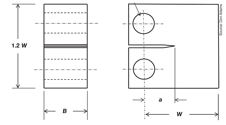
Fig. 1: Compact tension fracture toughness test specimen. Source: Don Adams
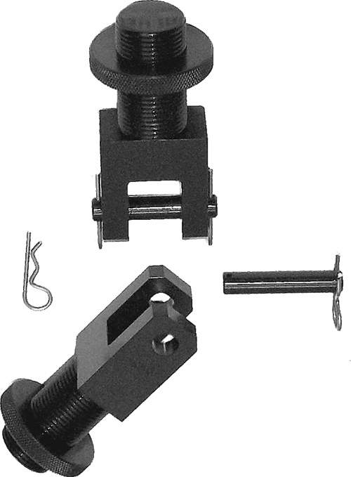
Fig. 2: A pair of compact tension tensile clevises and pins. Source: Don Adams


No specific standard yet exists for using the compact tension test method to determine the fracture toughness of composite materials, but the method has long been used for testing metals and unreinforced plastics. A number of ASTM and other standards apply for metals, and the plastics community adopted the metals method, with very little modification, in ASTM D 5045, “Plane-Strain Fracture Toughness and Strain Energy Release Rate of Plastic Materials.” This plastics standard states that its method bears many similarities to ASTM E 399, “Plane-Strain Fracture Toughness of Metallic Materials.”
Correspondingly, the compact tension specimen is used to test some types of composite materials that have limited orthotropy, including nanoparticle, particulate, whisker and short-fiber composites. For highly orthotropic (highly directionally reinforced) composites, ASTM D 5528, “Mode I Interlaminar Fracture Toughness of Unidirectional Fiber-Reinforced Polymer Matrix Composites”, is available. However, it utilizes a double cantilever beam specimen rather than a compact tension specimen.


A typical compact tension specimen is shown in Fig. 1 (second imge at left). A key parameter is the width, W, of the specimen in the direction of the starter crack relative to the thickness, B, of the specimen, since the assumption in the data interpretation is that a condition of plane strain is to be achieved. A further assumption is that the material remains linearly elastic to failure, or relatively so, as will be defined. A nominal ratio of W/B = 2 is specified in the ASTM standard. This ratio has been established in an attempt to achieve a balance between maintaining a condition of plane strain and retaining a crack tip material response that is reasonably close to linearly elastic. Thus, a ratio greater than 2 can be used if these conditions can still be maintained. For example, the standard permits using a ratio as high as 4 if certain conditions (discussed below) are satisfied.
The initial crack length, a, should be approximately equal to one-half the width, W. The ASTM standard, however, indicates that 0.45 ≤ a/W ≤ 0.55 is acceptable, that is, the “one-half” can vary slightly either way. If W is too small relative to a, plastic or viscoelastic material response at the crack tip may become significant, invalidating the test. Fig. 1 indicates a relatively wide slot in the specimen. This slot is machined into the specimen to slightly less than the desired length, a. Then a thin, sharp cutter, such as a razor blade, is carefully tapped into the end of the slot to propagate a sharp crack. This induced crack should be at least twice as long as the slot’s width. In Fig. 1, a includes the length of this induced crack. Because it is typically difficult to accurately measure a after the sharp crack is formed, it may be necessary to make the measurement after the test, when the specimen has been broken into two pieces and the fracture surfaces are exposed.
The compact tension fracture toughness test is performed by applying equal and opposite forces through the two holes in the specimen, to propagate the initial sharp crack. Tensile clevises are typically used to apply this loading. A typical pair of tensile clevises are shown in Fig. 2. ASTM D 5945 suggests the use of holes in the clevises that have flat bottoms rather than being round, so that the retaining pins can roll as well as rotate, to aid in maintaining specimen alignment. However, many of the metals standards specify round holes, and both flat-bottomed and round holes are commonly used. Even ASTM D 5945 permits the use of round holes if it can be demonstrated that the same results can be obtained.
As the tensile force is applied, a force vs. loading-point displacement curve is obtained. This displacement can be measured between the two loading pins, using an extensometer, clip gage or Linear Variable Differential Transformer (LVDT). However, simply using the testing machine crosshead displacement is usually acceptable. In any case, testing machine compliance and local deformation of the specimen at the loading pins must be accounted for, as necessary.
If the force vs. displacement plot obtained is an approximately straight line, with an abrupt drop of force to zero at the instant of crack growth initiation, indicating a material response reasonably close to linear elastic material behavior, a trial value of the critical stress intensity factor, K1c, termed KQ, can be calculated based on the maximum force attained, PQ. The value of KQ is calculated as a function of W, B, and the maximum force PQ (the formulas are given in ASTM D 5045). If the specimen was designed according to the previously discussed guidelines for selecting W, B, and a, this calculated value of KQ is almost certain to be valid, that is, K1C has been obtained. The check for validity is that B, a, and (W – a) must all be greater than 2.5(KQ/σy)2, where σy is the yield stress of the material, which is defined in the standard. Of course, if the test proves invalid, then one or more of the values (W, B, a) must be modified and the test repeated.
If the force-displacement plot is not linear, the specimen initial compliance (the reciprocal of the initial slope of the plot) is determined from the best-fit straight line for the initial portion of the curve. Then a second straight line is drawn, with a compliance 5 percent greater than the first line. The intersection of this line with the force vs. displacement curve is used to determine PQ. The remainder of the process to obtain KIC is the same as given above for the linear material response.
The strain energy release rate, GIC, can be calculated, having obtained the value of KIC, using
GIC = (1-μ2)KIC2/E
where μ is the Poisson’s ratio and E the elastic modulus of the material being tested. However, it is usually more reliable to determine GIC directly, by integrating the area under the experimentally determined force vs. displacement curve.
As this summary indicates, the procedure for determining fracture toughness and strain energy release rate using the compact tension test is relatively straightforward, even though the basic concepts of fracture mechanics sometimes seem abstract. ASTM D 5045 has a well-written tutorial on the process.


.jpg;maxWidth=300;quality=90;format=webp)


Related Content

Composite test methods (and specifications) for fiber-reinforced concrete structures
While initially focused on transitioning existing standards published by the American Concrete Institute, the relatively new ASTM Subcommittee D30.10 is developing new standardized test methods and material specifications for FRP composites.
Read More
Multi-scale 3D CT imaging enables digital twinning, high-fidelity simulation of composite structures
Computed tomography (CT) provides highly accurate 3D analysis of internal microstructure, performance simulation of carbon fiber/PEEK satellite strut.
Read More
Notched testing of sandwich composites: The sandwich open-hole compression test
A new ASTM-standardized open-hole compression test method seeks to determine the notch sensitivity of sandwich composites.
Read More
Material equivalence testing in shared composites databases
In response to traditionally proprietary polymer matrix composites (PMC) qualifications, NCAMP continues its efforts to make material property databases publicly available.
Read MoreRead Next

CW’s 2024 Top Shops survey offers new approach to benchmarking
Respondents that complete the survey by April 30, 2024, have the chance to be recognized as an honoree.
Read More
From the CW Archives: The tale of the thermoplastic cryotank
In 2006, guest columnist Bob Hartunian related the story of his efforts two decades prior, while at McDonnell Douglas, to develop a thermoplastic composite crytank for hydrogen storage. He learned a lot of lessons.
Read More
Composites end markets: Energy (2024)
Composites are used widely in oil/gas, wind and other renewable energy applications. Despite market challenges, growth potential and innovation for composites continue.
Read More