
Carbon is the choice for amphibious LSA floats
Superlight, landing-gear-equipped design gives light sport aircraft builders an option for land and water.

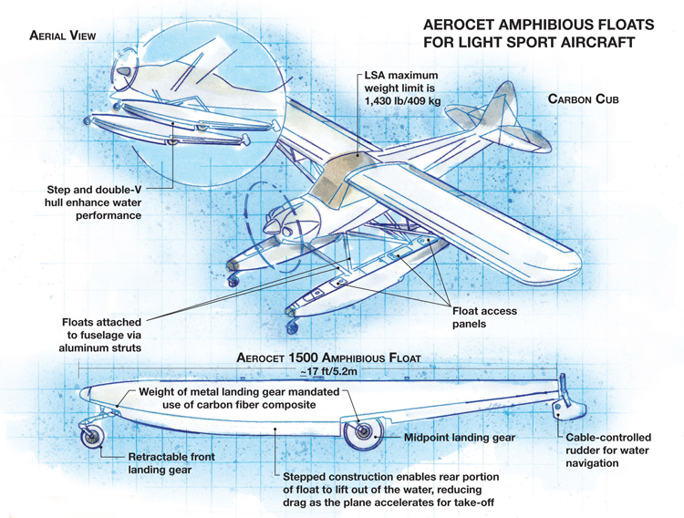
Aerocet Amphibious Floats for Light Sport Aircraft Illustration: Karl Reque
Aerocet’s jumbo 5850-series floats on a DeHavilland DHC-2 Beaver seaplane. Note that the floats on the Beaver are water only (no landing gear). Source: Fliegen Works
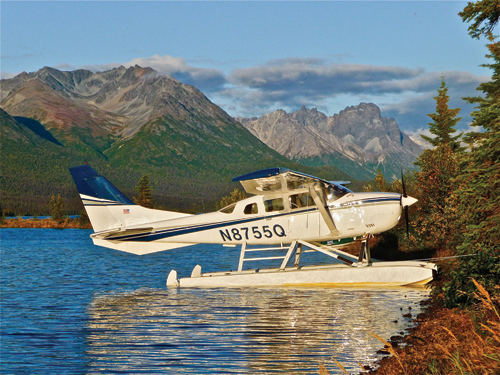
Aerocet's large 3400-series floats on a Cessna 206. Floats are sized for the individual plane model. Source: Aerocet
In this rendering of an LSA fitted with 1500-series carbon fiber-reinforced floats, the landing gear components are shown extended and compartment access panels are visible on float top surfaces. Source: Aerocet
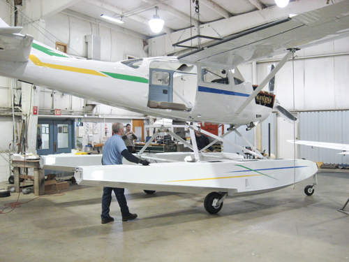
Aerocet floats are shown here in the process of being attached to an aircraft. The “step” on the float underside and the attachment struts are clearly visible. Source: MMS Aviation


Design Results:
- Lightweight carbon/vinyl ester shells meet ambitious weight target necessitated by LSA weight restrictions.
- Laminate shell design offers stiffness to withstand landing loads, even with a fully loaded aircraft.
- If damaged, lower monolithic carbon laminate can be repaired readily at room temperature.
General aviation pilots embody freedom. They have the ability to fly anytime — packing liquids and gels in containers larger than 3 oz and without removing their shoes — to anywhere, including destinations not served by commercial carriers. Pilots with amphibious planes, those equipped with floats that enable both water and airstrip landings, have their freedom multiplied a thousandfold because a float-equipped plane can access lakes and rivers, even in the remote backcountry. When those floats are made from composites, rather than aluminum, they offer freedom from corrosion in addition to weight savings that permit them to carry more cargo. And for Aerocet (Priest River, Idaho), composites also give airframers the freedom make smaller, weight-limited light sport aircraft (LSA) amphibious.


Founded in 1987 by aviation pioneer Tom Hamilton (who designed and developed the Glasair kit plane and now works with Quest Aircraft Co. in Sandpoint, Idaho), Aerocet specializes in composite floats for the general aviation community. Using aerospace-grade designs and materials, Aerocet competes head to head with traditional aluminum float designers. The company is about to release a new, smaller carbon composite float, dubbed the 1500 series, for LSA aircraft.
“We didn’t set out to reinvent the wheel,” says Aerocet’s general manager, Matt Sigfrinius, who points out that floats have been in use for nearly 100 years. “We’ve taken what we felt were the best concepts and combined them with our experience in the industry as well as customer feedback, to create our products.” The company’s designs are popular with customers who want a sleeker product without metallic corrosion. Notably, Aerocet is the only composite float manufacturer with products type-certified by the U.S. Federal Aviation Admin. (FAA), and its offerings range from the compact 1500 series up to its current development project, floats for Quest Aircraft’s heavyweight, 10-passenger Kodiak utility plane.
A complex design brief
Although a float necessarily must have a smooth and aerodynamically slippery shape, it also must provide sufficient buoyancy and stability to support the plane on the water. Therefore, its length and displacement volume must be precisely matched to an aircraft’s make and model. Stability is a function of float length, and float length is tied to the aircraft’s fuselage length. Displacement is determined by the plane’s gross weight. Simply put, the bigger the aircraft, the larger and longer the float. “One float has to be able to support the entire weight of the aircraft, plus 10 percent, in accordance with the FAA’s Federal Aviation Regulations (FAR) 23.751,” Sigfrinius points out, “so we have to really balance the competing goals of light weight vs. size for a fully loaded plane.”
The 1500’s design was targeted to fit a high-performance LSA, the Carbon Cub, a re-creation of the classic Piper Cub manufactured by Cub Crafters (Yakima, Wash.). Weight was the critical consideration, because the Cub, in float-plane configuration, is limited by the FAA’s LSA rules to a speed of 120 knots/138 mph and a maximum gross weight of 1,430 lb/650 kg. Considering that the plane’s empty weight, without floats, is about 900 lb/409 kg, and that a pilot and passenger could add 300 lb/136 kg and 20 gal of fuel would contribute another 180 lb/82 kg, carbon fiber had to be a candidate reinforcement if Aerocet was to meet a very ambitious weight goal. Further, says Sigfrinius, the decision was made to create an amphibious float — that is, to incorporate landing gear so the plane could make conventional hard-surface landings. The added weight of the wheels and hydraulic mechanisms for retracting the gear made carbon fiber an absolute necessity.
Aerocet designers also had to take into account a host of additional complicating factors: Where should metallic attachment points be placed for the aluminum struts that would connect each float to the Carbon Cub’s fuselage? How would the floats accommodate the cables that operate small, rear-mounted rudders that control the plane’s direction during water taxiing? What should be the shape and location of the “step” on the lower hull that enables the float to rise up out of the water “on plane” to minimize drag and increase speed to facilitate takeoff? Placement of the step is one more feature that must be customized to the aircraft, with specific reference to its center of gravity (CG). Because the float would be equipped with retractable gear at its front and its midpoint (see drawing, top image), small amounts of water could be forced into the float interior, so a means for extracting water was needed.
Another important consideration, Sigfrinius adds, is the angle formed between the flat upper deck of the float and the aircraft’s wing — a number that is proprietary to Aerocet. That angle can affect drag during flight and in the water. The selected angle for the Cub, a tail-dragger, determined the length of the struts that attach the floats to the plane and the cross-braces that connect the floats.
Durable and repairable
To create the 1500 float, the designers first downsized the company’s “tried-and-true” 2200-series float and reconfigured its layup to accommodate higher-stiffness carbon fiber, using SolidWorks CAD software from Dassault Systèmes SolidWorks Corp. (Waltham, Mass.). The float was modeled in two parts, top and bottom, with the top shell configured as a foam-cored sandwich. Sigfrinius explains that Cub Crafters already had provided guidance regarding where struts should be attached to the plane’s airframe. This determined both the placement of metal fastener inserts in the upper shell and the length of the aluminum tube struts.
The bottom shell, which is subjected to tensional loads during landings, was conceived as a solid, monolithic laminate to optimize durability. For buckling resistance, the design included several transverse bulkheads that divide the lower shell into discrete compartments. One compartment serves as a storage locker, and the others provide buoyancy. The two shells would be joined via adhesive bonding, with the joint located above the at-rest waterline. A thin, extruded aluminum strip would be bonded over the joint to protect it in service. The control cables for the rudders were mounted on the float’s exterior and connected to the rudder pedals in the cockpit by means of a pulley system. Small “pump-out cups” were incorporated in the upper shell for water extraction.
The modeled float concept was then subjected to finite element analysis (FEA) using COSMOSWorks software, part of the SolidWorks software suite. The software enabled virtual simulation of the float’s performance when subjected to the multiple G-forces of water landing under a variety of aircraft gross-weight scenarios before Aerocet started fabrication of a physical prototype.
After the design was optimized, and based on virtual testing of the model, production prototypes were created in fiberglass molds designed and produced in-house by Aerocet. Prepped tools were sprayed with gel coat manufactured by CCP Composites (N. Kansas City, Mo.). Then the shells were layed up with carbon fiber fabrics and, for the upper shell sandwich, a core of Divinycell foam supplied by DIAB Sales Inc. (DeSoto, Texas). The dry layups were infused with a resin supplied by Reichhold Inc. (Research Triangle Park, N.C.), followed by room-temperature cure. Says Sigfrinius, “We’ve progressed from wet layup to infusion for all of our parts, which ends up saving man-hours and weight.” A structural adhesive from ITW Plexus (Danvers, Mass.) securely bonds the two shells and is used to attach the aluminum wear strip.
The backcountry beckons
Completed prototypes will be tested to failure using hydraulic fixtures fitted with reaction pads to verify the design and modeling predictions and to comply with the FAA’s Technical Standard Order (TSO) for floats. Then the ultimate test will be actually flying a Carbon Cub outfitted with the floats. This step will ensure that the float attachment angle is correct, and it will enable engineers to fine-tune the length and angles of the struts.
“You could say that float design involves some art along with computer modeling,” observes Sigfrinius, who is a licensed pilot himself, with float-plane experience. “Because of the added weight and subsequent drag, you really can’t tell until you fly it,” he maintains, adding that if damage occurs to the underside of a float — a typical scenario is impact with a submerged log while landing or taking off — it is possible for pilots to buy materials at hardware stores and complete the repairs themselves at room temperature.
The 1500-series is now in preproduction, but Aerocet says it will be available for sale in early 2013. Expecting that the number of LSA aircraft will grow significantly, Sigfrinius sees demand for amphibious aircraft increasing for at least the next decade, as pilots seek to expand their recreational destinations. “It’s a very big market for us,” he says, “and we see consistent demand from LSA pilots over the next few years. But we need to get younger pilots involved!”


.jpg;maxWidth=300;quality=90;format=webp)


Related Content

Infinite Composites: Type V tanks for space, hydrogen, automotive and more
After a decade of proving its linerless, weight-saving composite tanks with NASA and more than 30 aerospace companies, this CryoSphere pioneer is scaling for growth in commercial space and sustainable transportation on Earth.
Read More
One-piece, one-shot, 17-meter wing spar for high-rate aircraft manufacture
GKN Aerospace has spent the last five years developing materials strategies and resin transfer molding (RTM) for an aircraft trailing edge wing spar for the Airbus Wing of Tomorrow program.
Read More
Materials & Processes: Fibers for composites
The structural properties of composite materials are derived primarily from the fiber reinforcement. Fiber types, their manufacture, their uses and the end-market applications in which they find most use are described.
Read More
Plant tour: Joby Aviation, Marina, Calif., U.S.
As the advanced air mobility market begins to take shape, market leader Joby Aviation works to industrialize composites manufacturing for its first-generation, composites-intensive, all-electric air taxi.
Read MoreRead Next

From the CW Archives: The tale of the thermoplastic cryotank
In 2006, guest columnist Bob Hartunian related the story of his efforts two decades prior, while at McDonnell Douglas, to develop a thermoplastic composite crytank for hydrogen storage. He learned a lot of lessons.
Read More
CW’s 2024 Top Shops survey offers new approach to benchmarking
Respondents that complete the survey by April 30, 2024, have the chance to be recognized as an honoree.
Read More
Composites end markets: Energy (2024)
Composites are used widely in oil/gas, wind and other renewable energy applications. Despite market challenges, growth potential and innovation for composites continue.
Read More