
Carbon composites move beyond racing yachts into commercial and military marine applications.
Marine carbon composites move beyond racing yachts into commercial and military vessels.


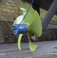
Source: QinetiQBecause they are thicker than their metal counterparts, the QinetiQ carbon-composite blades improve propulsion efficiency and decrease observability.
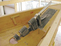
Source: GMT CompositesScheherazade's stemhead fitting withstands 195,000-lb loading with a lightweight carbon/epoxy design.
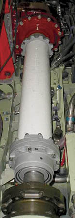
Source: ACPTCarbon-composite driveshafts on the Expeditionary Fighting Vehicle represent a new application of an established technology.
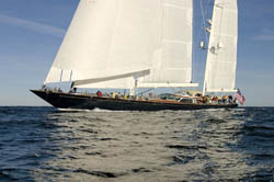
Source: Hodgdon YachtsScheherazade takes to the seas with carbon-fiber components aloft, astern, abow and otherwise.
Carbon composites are making headway into marine vessels, following a developmental pattern similar to that seen in the automotive market. Some of the earliest experiments involved components for racing boats, where high strength-to-weight ratio was absolutely critical and cost was not an issue. Carbon-composite hulls were first permitted in America's Cup racing yachts in 1992. Since then, in competitive and other high-end applications, marine designers and fabricators have gained experience and refined processing techniques. "People have been working with carbon composites for well over 20 years now," says Will Rogers, sales manager for marine fabricator GMT Composites (Bristol, R.I., U.S.A.). "We have a better database of knowledge and a greater confidence in them."
While price is still the principal factor restricting carbon fiber primarily to custom, high-end vessels, commercial boatbuilders are learning to tailor laminate designs to achieve the greatest performance with the least weight. As a result, carbon composites are now commonplace in a few highly loaded production-boat components, such as masts and spinnaker poles that support sails.


Recently, marine designers have begun to exploit carbon's potential for vibration damping and hydrodynamic tailoring, to overcome additional marine-specific challenges. As the following examples illustrate, specialized application of carbon fiber is an emerging trend in both commercial and military marine vessels.
Scheherazade
When the 273-metric tonne/300-ton Scheherazade first set sail from East Boothbay Harbor (Maine, U.S.A.) in December 2003, it was the biggest sailing yacht built in the Western Hemisphere. This 47m/154.5-ft ketch measures "eight inches shorter than a Boeing 757," reports Ted Smith, company representative of yachtbuilder HodgdonYachts (East Boothbay). The elegant vessel's interior is adorned with more than 500 hand-carved wood components, and the vessel is a showcase for Hodgdon's trademarked cold-formed wood/epoxy hull technology.
While megayachts don't face the competitive demands of America's Cup racers, their owners demand high performance, so Scheherazade's builders also employed carbon composites. In common with many newer high-performance yachts, Scheherazade's 56.4m/185-ft and 33.5m/110-ft masts, its booms and some rigging components are made from carbon/epoxy composites. But the yacht includes several uncommon applications of carbon fiber, as well.
In the largest, carbon plies make up 12 percent (by volume) of the deck's structure, which forms the top, with the hull providing the other "sides," of an integrated structure functionally similar to a box beam. The deck is built on top of Douglas fir deck beams. The sandwich construction is bonded together with epoxy. It consists of a layer of 1.25-cm/0.5-inch marine-grade plywood topped by four layers of carbon/epoxy, then 3.8-cm/1.5-inch Divinycell foam core supplied by DIAB Inc. of DeSoto Texas, U.S.A. (except in places that serve as equipment foundations, where solid Douglas fir blocking is used). Then an additional three layers of carbon/epoxy are layed down, followed by 1.9-cm/0.75-inch teak decking. To achieve the required strength at the designed weight, Hodgdon used biaxial carbon fabrics from Vectorply Corp. (Phenix City, Ala., U.S.A.) wet out with Gougeon Bros. (Bay City, Mich., U.S.A.) Pro-Set epoxy, in a vacuum bagged, room-temperature-cured layup. While always important, weight reduction is critical above the boat's center of gravity, Smith points out. "The more weight is placed away from the center of gravity, the more the boat tends to pitch or 'hobby horse,'" he explains. "So weight at the ends is bad; weight aloft is worse."
GMT Composites contributed three other major carbon structures. One was the yacht's 2.2m by 1.2m by 0.3m (6-ft by 4-ft by 1-ft) stemhead fitting assembly, which is integral to the forward part of the bow and attaches the stainless steel head stay to the hull. The head stay is the beam that extends out from the bow to support the bottom of the forwardmost sail. The fitting has a breaking strength of 88,451 kg/195,000 lb, sufficient to handle "the immeasurable shock loading when a sail boat starts knifing into seas," Smith reports, noting that the stemhead fitting weighs only 209 kg/460 lb (see photo, this page). GMT's Rogers estimates that to accommodate such loads with a metal or wooden stemhead fitting could quadruple the fitting's weight.
The stemhead fitting's four stainless steel bushings, which hold the head stay, sit on an angled composite faceplate that is supported by two web faces and a neat epoxy fillet. The plate, web faces, and bushing-surround are solid laminates individually hand layed, using unidirectional carbon/epoxy prepreg from Newport Adhesives and Composites Inc. (Irvine, Calif., U.S.A.). Fiber in the bushing surrounds is oriented at 90° to the bushing axis. In the web faces, angles are 60° and 90°; in the faceplate, angles are 0° and 90°. After vacuum bagging and oven cure at 121°C/250°F, these pieces are assembled. A secondary wet layup positions reinforcing straps over the bushings and bonds them to the faceplate. The straps are made from Gougeon Bros.'s WEST SYSTEM epoxy reinforced with biaxial fabric from SP (Burlington, Ontario, Canada). They are cured at room temperature.
The other two GMT components support the propeller shaft. The first, an 860-mm/34-inch vertical strut, extends downward from the hull to stabilize the exposed propeller shaft. The strut consists of a hydrodynamically shaped foil and a 305-mm/12-inch diameter bulb that encases the shaft. At 136 kg/300 lb, the composite strut is a mere one-sixth the weight of a conventional brass strut. Yet weight savings was not the primary design driver: Smaller than a comparable brass strut, the composite strut also decreases drag.
The strut was fabricated using wet layup and room-temperature cure. Part walls vary in thickness from 64 mm to 74 mm (2.5 inches to 3 inches), fabricated with internal layers of S-glass from Northern Fiber Glass Sales Inc. (Hampton, N.H., U.S.A.) to prevent galvanic interaction between carbon and steel components, and outer layers of SP carbon fabric all wet out with Gougeon Bros.'s 135/226 epoxy. The strut bulb is a solid laminate that was layed up on an aluminum mandrel while the strut foil also incorporated DIAB's Klegecell 75 foam core and was layed up in an open mold.
The second composite component supporting the propeller shaft is the 1,760-mm/69-inch long stern tube, which houses the shaft from the engine to the inside surface of the hull. It has an outside diameter of 305 mm/12 inches and an inside diameter of 203 mm/8 inches. It has the same basic construction as the strut bulb.
Special inserts inside the stern tube and the strut bulb accommodated the shaft bearings. To minimize voids in these critical areas, the parts were vacuum bagged, using equipment from Richmond Aircraft Products Inc. (Norwalk, Calif., U.S.A.).
Another relatively unusual structural use of carbon was in Scheherazade's pilothouse, which must endure brief loads as high as 60,000 lb when struck by waves and also serves as the attachment point for the control lines of the mainsail. Additionally, the 4.6m by 6.1m (15-ft by 20-ft) structure features large windows on all sides. Therefore top loads must be transferred to the deck through 14 mullions that divide the windows, some as narrow as 10 cm/4 inches. Furthermore, the low profile of the pilothouse (1.2m/4 ft high) means that headroom is at a premium -- so it was impractical to incorporate ceiling beams into the roof design. These factors and performance weight constraints prompted the carbon-composite design.
The pilothouse walls and top were fabricated as a unit by Goetz Custom Yachts (Bristol, R.I., U.S.A.) with a sandwich structure that was secondarily bonded to the deck floor. For aesthetic reasons, the structure's inside and outside geometries differ, making fabrication a challenge. Goetz built its male mold according to the inside geometry and layed up and oven-cured (100°C/212°F) the internal laminate. The company used SP and YLA Advanced Composite Materials (Benicia, Calif., U.S.A.) carbon/epoxy prepreg, primarily unidirectional tapes. (SP and YLA prepregs are compatible, Goetz explains, allowing his company to take advantage of the benefits of multiple suppliers.) Alcan Baltek Corp. (Northvale, N.J., U.S.A.) superlight balsa core material was bonded to this inside surface and sculpted to the outside geometry. Final geometry includes core material up to 150 mm/5.9 inches thick. Cutouts in the core accommodate load-bearing carbon/epoxy beams. These beams were layed up and cured separately, then positioned in the structure's roof. Finally, the outside laminate was layed up and cured in place.
QinetiQ propeller
Future warships may exhibit reduced underwater signatures if a propeller from QinetiQ (pronounced "kinetic," Rosyth, U.K.) moves into production. QinetiQ's prototype is the world's largest composite marine propeller with a 2.9-m/9.5-ft diameter (the largest in metal is about 9m/29.5 ft). The blades are solid laminates with centermost plies of carbon fiber. "However, we also used glass on the inner and outer surfaces to isolate the carbon from the environment and to provide some increased impact resistance on the blade surface," explains Catherine Kane, technology chief for QinetiQ Marine Structural Concepts. A tough polyurethane coating further isolates the carbon fiber. This is required because of the combination of a seawater environment and direct bolting and bonding to metal.
"The blade design was a retrofit solution which needed to be joined back
onto a nickel-aluminum-bronze hub," Kane notes.
QinetiQ developed proprietary techniques that enabled resin transfer molding (RTM) of the blades, Kane reports, "whilst maintaining structural performance in key areas, such as the leading and trailing edges." Dowty Propellers (div. of Smiths Aerospace, Cheltenham, U.K.) fabricated the blades, using RTM tools built by Delcam (Birmingham, U.K.). Reinforcement fabrics were supplied by Selcom Srl (Treviso, Italy). Huntsman Advanced Materials (Brewster, N.Y., U.S.A., formerly Vantico) provided an epoxy resin suitable for RTM. Wärtsiä Propulsion (Drunen, The Netherlands) manufactured the nickel-aluminum-bronze hub and blade stubs. The stubs have a rectangular cross-section and the hub features recesses that accommodate the blade roots. This design ensures proper load transfer from the blades.
The composite blades are expected to reduce propeller corrosion and last the full 25-year life expectancy of the ship. In that time, a nickel-aluminum-bronze blade would be replaced several times. "This was the principal driver for the project," Kane says, noting that the composite blades experience less wear from cavitation. Cavitation occurs when pressure gradients form vapor bubbles on the blade surface. Repetitive collapse of these bubbles creates unwanted noise and imparts localized stress, ultimately damaging the blades and reducing propulsive efficiency. "The use of the lighter composite material meant that the blades could be thicker without significantly adding weight to the propeller," explains QinetiQ project manager Colin Podmore. "Thicker blades offer the potential for improved cavitation performance, thus reducing vibration and underwater signatures." Furthermore, the blades weigh 35 percent less than comparable metal blades, reducing wear-and-tear on system components such as gears and bearings.
The composite propeller was designed to warship standards and installed on QinetiQ's 90m/295-ft long RV Triton trimaran warship prototype, the world's largest motor-powered triple-hull vessel. During sea trials completed in 2003, strain gauges were fitted to two of the blades and connected to a data logging system in the propeller tail cone. Gathered data will be used to validate the propeller's hydrodynamic and structural design models and to assess the acoustic performance of a rotating composite structure and evaluate the aft-end galvanic environment. The tests confirmed that the composite design provides a smooth take-up of power and reduces vibration on the main shaft compared to conventional propellers. In addition, cavitation inception speed was 30 percent higher than that of traditional, thinner metal blades. QinetiQ plans to assess and reduce the cost of composite fabrication and hopes to extend composites to the hub in future designs.
"The propeller is most likely to be taken up by minehunters, frigates and destroyers but could be adapted to any class of vessel. In addition, the technology is applicable to submarines," says QinetiQ's Gerry Hardy.
Expeditionary Fighting Vehicle
Last year, the U.S. Marine Corps (USMC) renamed its Advanced Amphibious Assault Vehicle (AAAV), dubbing it the Expeditionary Fighting Vehicle (EFV). The change reflects USMC's shift in focus from amphibious operations, primarily ferrying troops to the beach, to full sea-to-inland missions. The EFV is designed to launch forces from 37 to 46 km (20 to 25 nautical miles) at sea, transporting a crew of three and 17 combat-ready Marines to shore at speeds in excess of 37 kmh/20 knots -- three times faster than the current platform. On land, it will travel at 72 kmh/45 mph. USMC plans to purchase more than 1,000 EFVs from prime contractor General Dynamics Land Systems (Sterling Heights, Mich., U.S.A.) and will begin deployment in 2008.
These range and speed capabilities put the strength-to-weight ratio of highly loaded EFV components at a premium. Accordingly, Materials Sciences Corp. (Horsham, Pa., U.S.A.) designed two EFV components with carbon fiber. "This is unusual," notes Anthony Caiazzo, the company's technical director. "Historically, U.S. Navy composites have been limited to E-glass/epoxy or vinyl ester material systems." The parts were the 1.2m by 3m (4-ft by 10-ft) upper bow flap and the 0.6m by 3m (2-ft by 10-ft) transition flap. These flaps extend outward from the bow of the vehicle body to improve hydrodynamic performance during marine operations, but are designed to fold up during land operations.
Under U.S. Navy SBIR funding, Materials Sciences was tasked with reducing flap weight by 25 percent compared to the baseline aluminum-alloy design. Yet the company had to do so without changing the part designs or substantially increasing their cost. Additionally, the weight savings could not compromise impact resistance in the event of tool drops. "This is rather significant," Caiazzo notes, "since we are talking about tools associated with working on a 76,000-lb ground vehicle."
Initially, the company designed and prototyped an upper bow flap using S-2 glass, Caiazzo recalls, "but carbon fiber was ultimately needed to achieve the desired weight savings." The carbon upper bow flap achieved the 25 percent reduction, weighing in at just under 136 kg/300 lb. The carbon transition flap, at about 45.5 kg/100 lb, is 32 percent lighter than the aluminum alloy baseline.
Both parts were fabricated by Seemann Composites Inc. (Gulfport, Miss., U.S.A.), using the Seemann Composites Resin Infusion Molding Process (SCRIMP). Seemann used a Fabric Development (Quakertown, Pa., U.S.A.) carbon fabric woven from Toray Carbon Fibers America Inc. (Trophy Club, Texas, U.S.A.) intermediate-modulus carbon fiber. Fiberglass isolation plies were positioned wherever the flaps contact metal components. SCRIMP allows integral stiffeners, made from Vectorply stitched biaxial fabrics, to be infused and cured along with the laminates in one process. Both Alcan Baltek balsa and SP foam core materials were incorporated in the flaps. (Local loading determined where each core material was used.)
Designing a strong, lightweight hinge for flap deployment was a challenge. Materials Sciences used an integral hinge concept adapted from joining technology developed under the Modular Composite Bridge program sponsored by the U.S. Army Tank-Automotive and Armament Command (TACOM). Each hinge consists of an aluminum lug attached to the lower bow flap of the vehicle body, an aluminum pin (since redesigned in stainless steel but not yet installed), and a carbon composite lug integral to the flap. CCS Composites LLC (Benicia, Calif., U.S.A.) fabricated the composite lug from MS4A-35-1.0 carbon/epoxy bulk molding compound, supplied by YLA Advanced Composite Materials. A specialist in compression molding of carbon-reinforced composites, CCS molded 20-cm/8-inch long sections of the lug. Each section is made by placing a three-piece cavity insert in the tool (to provide the lug's pin holes) and charging the tool with a proprietary process to ensure good fiber orientation around the bore, thus maximizing structural properties. The resulting parts have near-net shape holes that are reamed to net shape during assembly. Seemann positioned the lug sections along the entire length of the flap layup. Technicians then wrapped the lug with Vectorply stitched carbon fabric. Laminates, stiffeners and wraps were infused with a toughened epoxy resin and cured.
Cost analysis has proved favorable for the transition flap, but General Dynamics will likely choose not to carry the composite upper bow flap into the next production phase. A revised aluminum upper bow flap has achieved the targeted weight at a lower cost.
The EFV's power systems also rely on carbon composites. For each vehicle, ACPT Inc. (Huntington Beach, Calif., U.S.A.) is making three carbon/epoxy driveshafts -- two marine and one automotive. The driveshafts are 70 percent lighter than steel driveshafts.
ACPT has been making composite driveshafts since 1982 for performance racing, marine and industrial applications. "For us," says marketing director James Heard, "the unique thing is that these shafts, designed for an assault vehicle, have a higher torque requirement." Compared to automotive shafts, the EFV marine driveshafts encounter about 15 times the torque.
Stress analysis begins the driveshaft design process. It determines a driveshaft diameter that ensures low torsional vibration and a resonance signature that does not interfere with operational speeds. EFV marine shafts are about 1 m/3 ft long with a diameter of approximately 15 cm/6 inches, and the EFV automotive shaft is approximately 1.2 m/4 ft long, but with a smaller diameter (around 13 cm/5 inches) because the torque is lower. Wall thickness then is ascertained to provide adequate stiffness and buckling strength under expected loads. EFV driveshafts require about four times greater thickness than typical automotive driveshafts to meet the torque requirement.
The shafts are fabricated with McClean Anderson (Schofield, Wis., U.S.A.) filament winding equipment, using an ACPT resin formulation. Cure temperature is 175°C/350°F. To prevent galvanic interactions, ACPT uses an electrical insulating material between the carbon composite and metal interface and a corrosion-resistant coating on the metal couplings and other connecting metal components. A proprietary metal flange attaches the driveshaft to the shear plate assembly and gear coupling in the drivetrain.
The shafts are assembled with a shear pin to prevent overload damage. This mechanism allows the shaft to spin freely if, for example, floating debris were to jam the waterjet(s). The driveshaft assembly also includes a center-member capture feature. This proprietary technology holds the driveshaft in place even if it is damaged in battle, preventing it from flying out and endangering the vehicle occupants.
ACPT is currently working on the next generation of these driveshaft assemblies, which will further reduce weight by consolidating metal components. The composite shaft will be lengthened slightly because the new metal parts will span a shorter distance. The new designs also will accommodate alterations made in the transmission systems and waterjets, which have undergone several iterations of change during two years of development.
Nine Operational Assessment Vehicles and one Live Fire Vehicle are being built during the EFV's System Development and Demonstration phase, and several already are undergoing field tests. Carbon composite components will be proving their mettle during these trials.
The now and the not yet
Carbon composites have extended their reach into marine-vessel applications, but volumes remain small. For the foreseeable future, marine applications are regarded as a strong market for glass-reinforced composites, expected to yield only specialized applications to carbon. Nevertheless, these applications should represent substantial sources of business for marine manufacturers with carbon fiber expertise.


.jpg;maxWidth=300;quality=90;format=webp)
Related Content

Plant tour: ÉireComposites, Galway, Ireland
An in-house testing business and R&D focus has led to innovative materials use and projects in a range of markets, from civil aerospace to renewable energy to marine.
Read More
Time Bicycles to modernize composite bicycle manufacturing
With the aid of KraussMaffei, Clemson University and SC Fraunhofer USA Alliance, Time anticipates a transition to HP-RTM for more efficient carbon fiber bike frame manufacture, plus a new facility in South Carolina.
Read More
Materials & Processes: Fabrication methods
There are numerous methods for fabricating composite components. Selection of a method for a particular part, therefore, will depend on the materials, the part design and end-use or application. Here's a guide to selection.
Read More
Materials & Processes: Resin matrices for composites
The matrix binds the fiber reinforcement, gives the composite component its shape and determines its surface quality. A composite matrix may be a polymer, ceramic, metal or carbon. Here’s a guide to selection.
Read MoreRead Next

Composites end markets: Energy (2024)
Composites are used widely in oil/gas, wind and other renewable energy applications. Despite market challenges, growth potential and innovation for composites continue.
Read More
From the CW Archives: The tale of the thermoplastic cryotank
In 2006, guest columnist Bob Hartunian related the story of his efforts two decades prior, while at McDonnell Douglas, to develop a thermoplastic composite crytank for hydrogen storage. He learned a lot of lessons.
Read More
CW’s 2024 Top Shops survey offers new approach to benchmarking
Respondents that complete the survey by April 30, 2024, have the chance to be recognized as an honoree.
Read More