
Big Blades Cut Wind Energy Cost
Rapid growth rate of composite-intensive conversion systems drives market competition and innovation.


Source: Global Energy ConceptsThirteen tons beats the weight bogey for a 54m blade in this plotted trend for commercial blades.
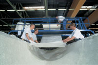
Source: LM GlasfiberSpecial materials handling device simplifies layup of multiple plies of fiberglass fabric into big molds for vacuum infusion processing.
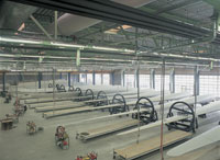
Source: LM GlasfiberPatented automated handling equipment transports blades between stations for secondary processing and provides easy worker access to the blades.
The first electricity-generating wind turbine was erected, it is said, in 1891, in Askov, Denmark, to benefit village farmers. More than 100 years later, the global cumulative installed wind turbine capacity, measured in megawatts (MW), increased over a five-year period at a compound annual growth rate of 32.6 percent, from 6,070 MW at the end of 1996 to 24,927 MW at the end of 2001. As of September 2002, the European Wind Energy Assn. (EWEA, Brussels, Belgium) reported worldwide, cumulative wind energy installed capacity as 27,257 MW, of which 74 percent (20,284 MW) is in the European Union. Wind energy now accounts for 18 percent of national electricity consumption in Denmark and 4 percent in Germany, according to the EWEA, which notes that about 80 percent of all wind turbines sold worldwide are manufactured by European companies. Rapid growth has driven continuous innovation and intense competition among wind turbine manufacturers.
Blades, which typically represent between 15 and 20 percent of the total cost of a wind turbine, are designed to capture the greatest possible energy from the wind. The blades connect to the rotor hub, mounted atop the tower within the nacelle, along with the drive train, gear and generator that convert the captured energy into electricity.


Two different control technologies are used to control the wind loads placed on the blade and turbine during excessive wind speeds: pitch control and stall control. Pitch control is used for most of the largest turbines, where the blade pitch, or angle into the wind, is varied to exploit wind speed to the best advantage. In high winds, the blades can be turned to reduce the impact of wind forces on the blades and protect the drive train from excessive spikes of energy. The blades turn around their longitudinal axis to change pitch and control their aerodynamic properties. Stall control is used for smaller blades. In this case the blades attach to the hub at a fixed angle, which ensures a proper limitation of the power generated by the rotor.
LONGER BLADES INCREASE POWER, ECONOMY
In today's highly competitive wind energy market, manufacturers of wind turbine blades are extending their reach to give power companies the greatest possible generated power at the lowest cost. Longer blades harvest a larger wind area and are installed on taller towers, placing them in a better position to capture the greater wind speeds typically found farther up from the ground. Since power generated by wind is proportional to the cube of the wind speed, even a slightly higher wind speed can dramatically increase electricity generation. For example, a 16 miles per hour (mph)/26 kilometers per hour (kph) wind speed will generate nearly 50 percent more electricity than wind at 14 mph/22.5 kph. Longer blades, together with advances over the past 20 years in rotor controls, generators, composite materials and blade design, have boosted wind turbine generating capability from 25 kilowatts (kW) using a 10m/33-ft diameter rotor, to 1.5 MW, with a 72m/236-ft diameter rotor. (Rotor diameter is approximately the length of the blade doubled, plus the diameter of the rotor hub. Rotor radius is one-half the diameter.) Historically, the cost of generated kilowatt hours (kWh) drops exponentially with increased power, an important element in the economics of wind energy. This is particularly dramatic when small and large wind farms are compared. For example, the American Wind Energy Assn. (AWEA, Washington D.C., U.S.A.) estimates the cost per kWh for a 51-MW project is 40 percent less than the cost for a 3-MW project. The economics for wind farm operators and power companies clearly point to bigger blades. Equally clear is the necessity for advanced technology and production economics in the manufacture of big blades.
LM Glasfiber (Lunderskov, Denmark) began blade production in 1978 and by the end of 2001 had captured 40 percent of the global market share of all blades. Steen Broust Nielsen, group marketing manager, attributes its success, in large part, to its integrated design and manufacturing approach. "We have under the same roof aerodynamics, structures, materials, manufacturing and testing expertise and facilities," Nielsen says. "Our main goal is a turbine that can provide the lowest possible cost of energy per kWh. Manufacturability of our designs is a critical element in achieving this goal and manufacturing engineering works closely with LM's in-house design engineers in R&D and throughout all projects." LM designs and builds its blades for a 20-year life cycle.
In general, LM's larger blades are designed for pitch control and smaller blades for stall control. For stall control in high wind speeds, LM uses a tip brake system that turns the tip to a 90° angle to the blade surface. When deployed, the angled tip brake slows down the rotor and brings it to a safe condition, using LM's own lightweight filament wound carbon shaft for the turning mechanism. LM's longest pure stall-controlled blade with a tip-brake system is its 31.2m/102 ft blade series. In some cases, a stall system is used with a turnable blade, called an active stall blade. The company's longest active stall blade is 36.8m/121 ft.
Reflecting the trend toward bigger blades, the company has increased its standard blade length from 19.1m/63 ft for 600 kW turbines produced in 1996, to 44.8m/147 ft for 2.75 MW turbines, which were recently put into production. In 2001, blades for turbines larger than 1,300 kW accounted for 30 percent of LM's revenue. This share increased to 49 percent in the first half of 2002, illustrating the increasing size of rotor blades.
Offshore development is driving the size of the turbines today, Nielsen says, due primarily to installation costs offshore. By increasing the size of turbines to 5 MW, for instance, fewer turbines are needed to generate the same capacity as greater numbers of smaller turbines. Design and construction of wind farms in water 17m/56 ft to 20m/66 ft deep can be extremely expensive, and installing fewer numbers of larger turbines results in significant savings in construction costs for tower foundations, power electronics and cabling from the shore.
BLADE LENGTHS GROW TO 54m AND 61.5m
In first quarter 2003, LM Glasfiber will introduce a 54m/177-ft long fiberglass composite rotor blade, providing a wind-sweep area of nearly 10,000m2/11,960 yd2 and a yet to be specified MW power capacity. A 61.5m/202 ft blade for a 5 MW turbine also is in development, with the prototype scheduled for the end of 2003.
The 54m/177 ft blade weighs 13 metric tonnes (13,000 kg/28,660 lb), which is below the curve for its length, as plotted by Dayton A. Griffin, engineering project manager for Global Energy Concepts LLC (GEC, Kirkland, Wash., U.S.A.). The plotted trend for commercial blades predicts a weight of 15 to 16 metric tonnes/33,069 to 35,274 lb for a 54m/177 ft blade, as shown in the chart above. In the plotted graph, Griffin adjusted all blade dimensions to a nominal rotor radius, estimating the radius of the 54m/177 ft blade at 56.8m/186 ft. The exact rotor diameter and radius are not given for the 54m/177 ft blade and Griffin's estimate assumes that the hub diameter is five percent of the rotor diameter (or hub radius is five percent of rotor radius).
Weight, or mass, is critical in a wind turbine, primarily due to gravity-induced bending loads. These loads fully reverse during each rotational cycle of the turbine rotor, placing considerable dynamic stress on the blade. "Reducing the gravity-induced bending loads is where decreased mass is of greatest importance," Griffin explains. The impact of gravity-induced bending loads is magnified in systems of 1 MW or greater and for such large turbines weight can become a critical design issue. "A lower blade mass for these sizes mitigates the need for additional reinforcements or planform modifications that might otherwise be needed to improve the load path between the inboard regions of the blade and the rotor hub."
MAKING A BIG BLADE THAT MAKES MONEY
Nielsen puts it this way: "Making a big blade is not that difficult; the trick is to make a big blade and still be competitive." He says LM's "smart engineering" pushes the envelope on standard, inexpensive materials and fast throughput in the manufacturing process.
LM product design and process development are concurrent and circular, in that development of a new composite rotor blade calls on an extensive database gathered over years of testing previous blade prototypes. The blades are physically tested to a lifetime equivalent of 20 years of operation, and the test results are fed back into FEA and material design software tools. Strain gauges mounted on the blades measure material performance during the tests and highlight both the strengths and limitations of the materials and the dynamics of changes in blade length and configuration.
LM has recently been accredited by Dansk Akkrediering (DANAK), the Danish national body for accreditation of services and products under the Danish Ministry of Economic and Business Affairs, to perform in-house testing of its blades.
DEFINING THE BLADE'S GEOMETRY
LM engineers first determine the external characteristics of the blade, using the company's proprietary FEA system and aerodynamic calculation software. In this phase, bending, noise generation, lightning protection, types of controls and other elements that affect the outside geometry are considered. The ability to manufacture composite materials in an unbroken, aerodynamic surface, to virtually any shape, is a tremendous advantage for tailoring the configuration of wind energy blades.
LM designs its blades so that they are pre-bent towards the wind (patent pending). In operation, the wind loads flex the blades so they become nearly straight, which is the best configuration for optimum performance. If the blades start out straight, they flex backwards, toward the tower, losing some of the clearance between the blade tip and the tower.
The blade bending mode — the frequency at which the blade bends — is also critical to the design. Frequency is the number of vibrations per second, expressed in Hertz (Hz), with 1 Hz equal to 1 cycle per second. The first (lowest) edgewise frequency causes the greatest edgewise bending deflections, usually deforming the blade in a continuous curve from tip to root. If the blade edgewise bending frequency is the same as the rotor rotational frequency, the combination can set up a dynamic resonant frequency that could damage the blade even before any wind bending load is applied. Therefore, the blade configuration should produce a blade bending mode frequency that is well above the rotor's rotational frequency.
To further improve the dynamics of the wind turbine, LM employs both a structural and a liquid damper system. The structural damper is a wide band of structural fiberglass composite incorporated into the layup. It extends from the tip of the blade along the leading edge about two-thirds of the length of the blade. In addition, a lightweight composite U-shaped channel is filled with a liquid designed to damp the edgewise vibrations of the blade and minimize fatigue loads.
Noise reduction is another design factor. In addition to noise from the gears, generator and other drive system elements, the airflow around the blade creates aerodynamic noise. LM Glasfiber's technical director Frank Nielsen says the company achieves greater noise reduction than is required by the decibel regulations of various countries and regions. He points out that the most critical issues regarding noise emission are aerodynamic tip design and the thickness of the trailing edge. Rotor blades are subject to three-dimensional airflows that present a considerable challenge to calculate and model. LM therefore launched an extensive field sound measurement program. The company gathered data with microphones mounted on multiple turbines and towers, measuring decibel emission under various conditions and blade configurations. In addition to field measurements, extensive wind tunnel experiments were conducted, Frank Nielsen says. The resultant design tapers to the thinnest possible trailing edge and a thin, pointed curve at the tip. "The strict tolerances applied to the blade tip and the thickness of the trailing edge make LM blades particularly silent," Frank Nielsen says.
The blade tip also must be protected from lightning. "An unprotected rotor blade is vulnerable to being struck by lightning," Frank Nielsen says. "When this occurs, an electric arc is created, which extends from the point of contact via other conductive components down to the root flange at the hub. This arc can reach a temperature of up to 30000°C/54032°F. The effect is an explosive expansion of the air contained within the blade. When lightning strikes a rotor blade without lightning protection, the resulting effects include surface damage, pressure damage, delamination, cracks in both the leading and trailing edges and melting adhesive. An unprotected blade also can suffer hidden damage from a lightning strike that may lead to serious long-term problems and significantly reduce the working life of the blade," says Frank Nielsen.
To avoid lightning damage, LM embeds one or more highly conductive metal alloy receptors in each blade. Receptors connect to rods or wire, which carry the lightning to the steel towers, where it goes to ground.
In shorter blades, a single receptor is located about 10 cm/4 inches from the tip. However, in the larger blades used in offshore installations and some on-shore wind farms, multiple receptors are spaced evenly lengthwise from the tip to the middle of the blades. A multiple-receptor system is currently in operation on LM's 36.8m/121 ft blades in the Middelgrunden offshore wind park, near Copenhagen.
CALCULATING THE LAMINATE DESIGN
Once the geometry is defined, all the operational characteristics of the rotor blade in terms of frequencies, rotational speed/frequency, type of controls, required mechanical strength, physical properties and other technical specifications are fed into LM's own laminate design program. "LM Blades is a proprietary CAD software program that assists us in calculating the optimal laminate design more quickly and precisely," Frank Nielsen says. The LM Blades' database incorporates the results of the company's years of prototype testing, an important tool in defining the best and most cost-effective materials, fiber architecture and ply schedule for each application.
Wing and rotor blade construction is typically a box spar design, in which upper and lower blade skins are molded separately and then bonded together, with the structural box spar bonded between the skin laminates. Heavy spar caps and shear webs in the box spar usually provide most of the required stiffness and strength. However, LM achieves strength and weight goals by a variant of the box spar design that relies on the skin, a balsa-core sandwich structure, as the primary load-bearing element.
FORMED WITH FIBERGLASS — FOR NOW
Research into the use of carbon fibers in large-scale rotor blade manufacture is underway, but "we do not use carbon in any of our mass-produced blades at the moment," Frank Nielsen says. "We have seen no reason, so far, with the current blade sizes to use a more expensive material than glass fiber, when it is fulfilling our requirements. Our current glass fiber materials are giving us high value. We are meeting strength goals as well as cost goals using these materials — all with the aim of providing the lowest possible cost of wind energy."
When all factors are entered and variables accounted for, the LM Blade program models a proposed laminate design. Based on the computer model, a prototype is fabricated and tested to failure. Frank Nielsen delineates procedures applied to every prototype: First, a static load test takes the blades to expected ultimate loads. Then dynamic testing simulates the fatigue loads a blade will experience over a 20-year life span (5 million cycles under load for five to six months). After this, it undergoes another static load test.
The design is tweaked according to the results. In some cases, testing indicates an over designed laminate, which means material can be removed to reduce weight and cost without sacrificing strength. The new design is modeled and another complete prototype is made and tested to failure in the same sequence, according to certification test standards; the process continues until engineers are satisfied they have identified the most cost-effective and lowest-weight design to meet the specified requirements.
The LM Blade program transfers the final design parameters to LM's in-house mold facility, where it is used to expedite development of the molds and other tooling for large-batch manufacture.
PROCESSING WITH VACUUM INFUSION
LM still makes some small blades by hand layup and open molding, but has switched most production to vacuum infusion, especially for larger blades. Fiberglass prepregs were considered but were judged unsuitable for cost-effective production. "Prepregs are more expensive and difficult to handle, especially for huge blades in the sizes of 40, 50, 60m/131, 164, 197 ft," Frank Nielsen says. Resin infusion was found to be more cost-effective and to provide better control over the materials than prepregs. "We determined that infusion was the best option for long blades. Key R&D points have been mold and tooling design and refining the process — developing optimum viscosity and flow characteristics of the resin, cure temperature, resin inlets and distribution media for thorough wetout."
In vacuum-assisted resin infusion molding (VARIM), dry reinforcements are layed up in a one-piece, gel-coated open mold and are then infused with resin by means of a vacuum-assisted process. Reinforcements are arranged in the mold in the number of plies and architecture designated by the design. The applied vacuum pulls the resin in through special inlets in the mold and presses the resin into the reinforcements. Proper inlet design and efficient distribution of the resin for thorough wetout of the reinforcements is critical to the success of the process. Compaction of the laminate squeezes air and excess resin out of the laminate and increases the fiber content.
After the top skin and bottom skin are molded and cured, the box spar is bonded onto the bottom skin while it is still in the mold. Adhesive is applied to the top side of the spar flange and to the skin bonding areas. The mold with the top skin is placed over the bottom mold/skin/box spar assembly and the bond is allowed to cure while the assembly is still in the mold. After the bond cures, the top mold is removed and the whole blade is demolded.
Patented automated handling equipment transports the cured part to a series of stations for de-flashing and grinding the bond line, addition of lightning protection and other finishing work. Since the blades are gel-coated in the mold, they do not require painting, which would involve an additional step.
LM has automated some handling systems and expects to implement more automation in the near future.
Through the entire process, cost-effective fiberglass composites are turning in high value in both cost and performance. Nielsen says LM has refined its design approach and manufacturing process to the extent that production rates can keep pace with the demands of this high-growth industry.
THE FUTURE: 12 PERCENT BY 2020
The EWEA recently launched its industry strategy, Wind Force 12: A blueprint to achieve 12 percent of the world's electricity from wind power by 2020. Its ambitious goal is based on installed wind power capacity by 2020 of 1,261,000 MW. The blueprint projects meeting this goal will result in cumulative savings of 11,768 million tons of CO2 and creation of 1.475 million jobs. No technical, economic or resource limitations are seen to prevent realization of this goal, but EWEA acknowledges that political and policy changes are required for the industry to reach its full potential. Wind Force 12 outlines installation of 230,000 MW of wind energy worldwide by 2010, a global wind power market worth (as of Dec. 14, 2002) a cumulative 133 billion Euros/~$130 billion (USD), which to the composites industry, represents a significant windfall.


.jpg;maxWidth=300;quality=90;format=webp)
Related Content

One-piece, one-shot, 17-meter wing spar for high-rate aircraft manufacture
GKN Aerospace has spent the last five years developing materials strategies and resin transfer molding (RTM) for an aircraft trailing edge wing spar for the Airbus Wing of Tomorrow program.
Read More
Thermoplastic composites welding advances for more sustainable airframes
Multiple demonstrators help various welding technologies approach TRL 6 in the quest for lighter weight, lower cost.
Read More
Composite rebar for future infrastructure
GFRP eliminates risk of corrosion and increases durability fourfold for reinforced concrete that meets future demands as traffic, urbanization and extreme weather increase.
Read More
Sulapac introduces Sulapac Flow 1.7 to replace PLA, ABS and PP in FDM, FGF
Available as filament and granules for extrusion, new wood composite matches properties yet is compostable, eliminates microplastics and reduces carbon footprint.
Read MoreRead Next

CW’s 2024 Top Shops survey offers new approach to benchmarking
Respondents that complete the survey by April 30, 2024, have the chance to be recognized as an honoree.
Read More
From the CW Archives: The tale of the thermoplastic cryotank
In 2006, guest columnist Bob Hartunian related the story of his efforts two decades prior, while at McDonnell Douglas, to develop a thermoplastic composite crytank for hydrogen storage. He learned a lot of lessons.
Read More
Composites end markets: Energy (2024)
Composites are used widely in oil/gas, wind and other renewable energy applications. Despite market challenges, growth potential and innovation for composites continue.
Read More