
Automating the CH-53K’s composite flexbeams
Accudyne doubles the part production rate and eliminates layup errors through stepwise automation of this primary structure’s complex hand layup process.

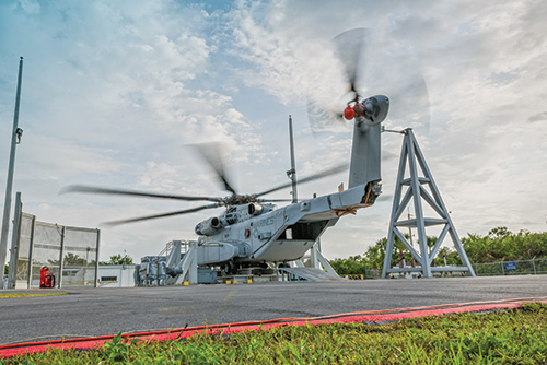
Sikorsky’s CH-53K heavy-lift helicopter will replace the U.S. Marine Corps’ active CH-53E rotorcraft. Here, the Ground Test Vehicle spins the main and tail rotor blades as part of a rigorous two-year test program. Accudyne Systems (Newark, Del.), worked with the Naval Air Systems Command (NAVAIR, Patuxent River, Md.) to develop automated methods for manufacturing the composite flexbeam, a flight-critical structure in the tail rotor. Source: Sikorsky
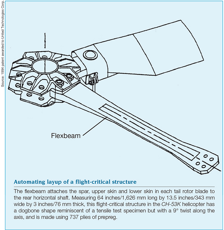
The flexbeam attaches the spar, upper skin and lower skin in each tail rotor blade to the rear horizontal shaft. Measuring 64 inches/1,626 mm long by 13.5 inches/343 mm wide by 3 inches/76 mm thick, this flight-critical structure in the CH-53K helicopter has a dogbone shape reminiscent of a tensile test specimen but with a 9° twist along the axis, and is made using 737 plies of prepreg. Source: 1994 patent awarded to United Technologies Corp.
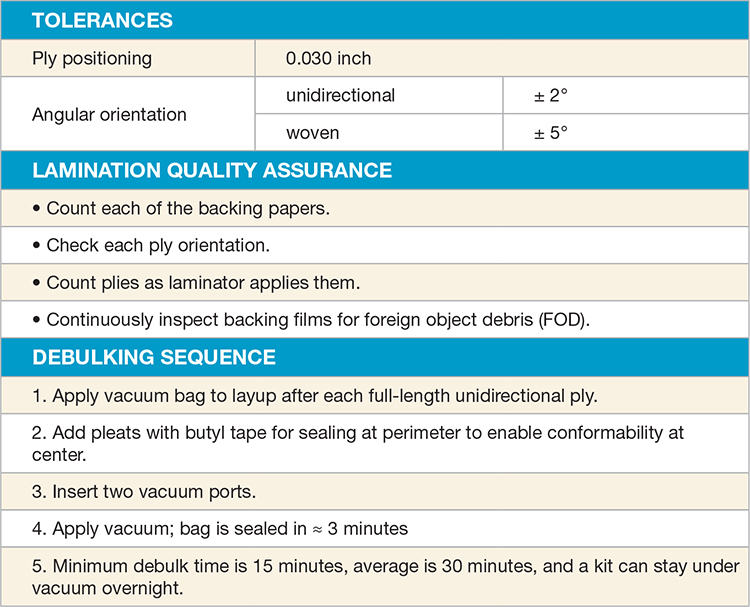
TAbel 1: Flex beam manufacturing tolerances, QA and manual debulking steps
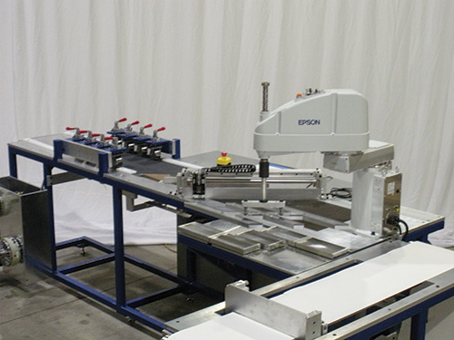
Fig. 1: Accudyne developed automated equipment to cut incoming 0° uni prepreg at a 45° angle and place it on backing paper to make a continuous roll of 45° unitape without stitching. Source: Accudyne
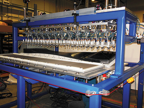
Fig. 2: To automate layup, Accudyne developed this conformable head with suction cup fixtures to pick up and deposit pre-cut plies. Source: Accudyne
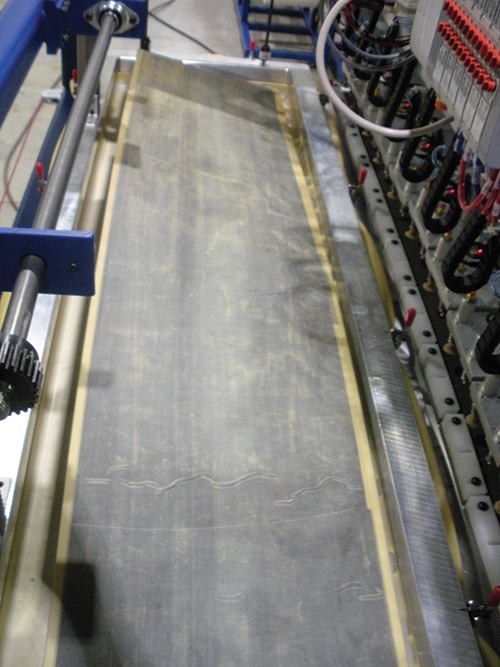
Fig. 3: For debulking, an elastomeric bladder was laid flat over the flexbeam layup, extending beyond the tool to seal against the table on which the tool sat. Vacuum was then applied through openings in the table surface, and supplied the pressure to conform the prepreg plies to the tool and to smooth any wrinkles that may have occurred during placement. Source: Accudyne
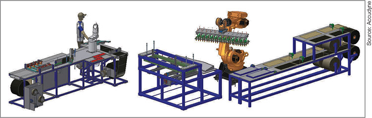
Fig. 4: Accudyne is in the process of completing and testing the modifications that will result in the finalized Concept 4 automated flexbeam production cell, including development of the cutting cell that will feed out materials from rolls and integration of a six-axis industrial robot. Bladder actuation will be conducted by a device on the gantry frame behind the table (see the dark grey mechanism behind the light grey wedge-shaped tool). Source: Accudyne


Scheduled for first flight this year and entry into squadron service in 2019, the U.S. Marine Corps’ (USMC) CH-53K heavy-lift helicopter is designed to raise the maximum gross weight ceiling of the currently used CH-53E to 88,000 lb (39,916 kg) without increasing its basic size. The operational goal is a three-fold increase in external load-carrying capacity, to more than 27,000 lb/12,247 kg over a mission range of 110 nautical miles/204 km. The extended payload capacity will be partially enabled by composites that include 35-ft/10.7m long fourth-generation rotor blades and a new, hybrid metal-composite airframe, which the OEM, Sikorsky (Stratford, Conn.), claims is more than 75 percent composite.
One of the enabling composite structures is the flexbeam, a flight-critical tail-rotor component that attaches the spar, upper skin and lower skin in each rotor blade to the rear horizontal shaft. The structure, 64 inches long by 13.5 inches wide by 3 inches thick (1,626 mm by 343 mm by 76 mm), has a dogbone shape reminiscent of a tensile test specimen, but with a 9° twist along its axis.


Each flexbeam incorporates 737 plies of prepreg. The USMC has ordered 200 aircraft. That’s a lot of hand layup. Worse, the current layup process involves multiple ply cutting, placement and debulking steps, which not only require extensive man-hours and inflate production cost, but also present health and safety concerns, because some of the steps are ergonomically challenging. In 2011, therefore, the Naval Air Systems Command (NAVAIR, Patuxent River, Md.) awarded a Phase II Small Business Innovation Research (SBIR) contract to custom manufacturing solutions developer Accudyne Systems (Newark, Del.), to automate layup.
For the CH-53K’s composite flexbeams, NAVAIR had made its goals clear:
- Accelerate production and cut labor cost by reducing cycle time from 40 to 10 hours per flexbeam.
- Eliminate operator ergonomic issues.
- Improve quality by laying 737 plies with no errors.
Theoretically, automation could minimize these risks, given the consistency of programmed machines in combination with continuous inline inspection via computer-based vision systems. Practically, Accudyne had the expertise and experience to provide the solution. The company had previously developed part-specific automated tape laying (ATL) and automated fiber placement (AFP) machines (that is, optimized for a single part or series of similar parts) and complete manufacturing cells. Further, it had developed a range of mechanized solutions for a wide variety of other operations, including preforming, robotic pick-and-place, ply consolidation and resin transfer molding (RTM), as well as noncomposites solutions to manufacturing and physics problems, such as a 75-ton “air crane” (lighter-than-air cargo transport), the world’s fastest lithium foil windup system for battery manufacture, and a six-station rotary cell that fabricates door windows.
Given NAVAIR’s brief and Accudyne’s history, it’s noteworthy that, rather than proceed directly to full automation, Accudyne adopted a graduated approach designed to validate, progressively, the ability of key automated system components to meet production rate and quality targets before its client had to commit to investing significant capital in a fully automated system.
Heavy man-hours for heavy-lift part
That decision was the result of a careful investigation. Development of equipment and process steps to meet NAVAIR’s production requirements was preceded by an analysis of the flexbeam’s manual layup process. Accudyne discovered that most of its plies are cut from 48-inch/1.2m wide unidirectional tapes supplied by Hexcel (Stamford, Conn.), roughly 60 percent IM7 and 40 percent S-2 Glass, both using 8552 epoxy resin. A smaller amount of IM7 fabric/8552 is used in 50 woven plies on the thick end of the flexbeam and 35 plies on the thin end. These pieces are cut and labeled automatically on a ply-cutting machine at Hexcel, assembled into 25 kits of approximately 25 plies each, and then stored in a freezer until lamination. To achieve the beam’s dogbone shape, plies that span the full length of the flexbeam are interspersed with short plies on the ends. In the center “neck” section, the plies are cut to one-third of the starting width and layed side-by-side, comprising three separate but adjacent plies and one full-width layer. These so-called “zebra” plies present a significant challenge in the already complex layup.
The manufacturing tolerances, the quality assurance tasks that ensure conformity to them, and debulking steps (required every 25 to 30 plies) add man-hours and extend cycle time (see Table 1, at left). Further, the monotony of manually laying similar plies offers significant potential for mistakes in sequencing. An incorrectly placed ply must be pulled up and a replacement cut. This is a time-consuming digression: The new material must be thawed, which can require an overnight wait. The new material itself might have defects and require replacement, further lengthening the delay.
One step at a time
“Many of our customers want to delve straight into fully automated production equipment,” notes Accudyne project engineer Tracy Dolan. “But NAVAIR was very cautious about jumping to that level from no automation at all.” Dolan also points outs, “without intermediate steps, it is hard to validate the increased production, improved quality and cost reductions needed to justify the investment in automation.” NAVAIR and Accudyne agreed that a step-wise approach would be best.
Based on its analysis, Accudyne developed nine automation concepts. Of these, four were selected and presented to NAVAIR (see Table 2, at left). “These were the most promising,” explains Dolan. “The ones in between [not shown] were hybrids.” NAVAIR, however, decided the best combination of low risk and high reward was to focus on the first two of the four Accudyne selected, beginning with Concept 1 and building to Concept 4. Accudyne would take graduated steps toward automation, automating first the process steps that require the most labor and time and present the highest risk for error: 45° laminating, conforming plies to the curved mold, and debulking.
45° unis on a roll
“There is no commercially available unitape with only +45° or only -45° fibers on a roll without stitching,” says Dolan. So Accudyne’s first undertaking was to build a 45° tape-making machine. Eight clamps engage the incoming roll of 0° unitape prepreg, which has already had its backing paper removed automatically. The unitape is then pulled, using a pneumatic system, and cut at a 45° angle with a knife. A robotic head supplied by EPSON Robots (Carson, Calif.) then places the 45° ply onto white backing paper (see Fig. 1, at right). “To make the continuous roll,” Dolan recounts, “we overlapped two half-thick 45° sections to enable a transition with a full thickness.” Accudyne had to show that the equipment could produce that joint within the ply thickness tolerance for the part. “The result is similar to film splicing, and produces a continuous roll of 45° unitape on backing paper,” she relates.
Automated ply placement and debulk
In Concept 1, the operator still manually cuts the lengths of 0° and 45° unitapes and stacks two plies at a time so a robot can pick them up and place them onto the curved flexbeam tool. “Our challenge,” explains Dolan, “was to develop a head that would pick up a ply layup, which could actually be two plies of short length or one full-length 64-inch ply, from a flat belt and place it onto a double-curved tool in the right location and without wrinkles.”
Accudyne had already developed an innovative pick-and-place robotic system for manufacturing T- and Z-stringers, which can integrate insertion of precut plies with shape forming for more than 160 different stiffener geometries. This system had reduced per-stringer cycle times that previously ranged from 30 to 60 minutes to a mere eight minutes. That system also alleviated the difficulty in aligning the ply packs by hand, which had previously resulted in excessive scrap and caused inconsistencies in dimensional integrity.
For the CH-53K flexbeam, the conformable head uses dozens of suction-cup fixtures to pick up the plies (see Fig. 2, at left). Dolan clarifies that the full production machine will have this conformable head attached to the end of a six-axis robot (see Fig. 4, at left). Accudyne’s prototype did not yet incorporate a fully actuated robotic arm because it first had to demonstrate that the conformable head could pick up plies (see the gray-and-white tray in the foreground of Fig. 2) and place them onto the curved mold (see the black flexbeam layup directly beneath the suction cups in Fig. 2).
For debulking, an elastomeric bladder was laid flat over the part and tool, extending beyond the tool edge to permit operators to seal it against the table on which the tool sat (see Fig. 3). Vacuum is pulled through openings in the table surface. This conforms the prepreg plies to the tool and smoothes small wrinkles that might occur during placement. In the fully automated production equipment, the bladder will be positioned on the table and removed by a device mounted on a separate gantry frame located behind the tool table (see Fig. 4).
“In the beginning, we thought debulking would be our high-risk area of this work cell,” Dolan relates, “but it became less so as we understood the requirements and nuances.” In the manual process, debulk was necessary every 25 to 30 plies and consumed 15 to 30 minutes each time. Dolan recalls that Accudyne looked at many alternatives, including using two layup tools and debulking according to the manual process specs but nesting certain tasks within the automation. “In the end,” says Dolan, “we realized we could debulk as part of the automation while the machine maneuvered to grab the next set of plies to place.” In this scenario, debulking is performed every one to two plies, but each debulk lasts only one minute.
Prototype testing
After the two machine prototypes were built, Accudyne tested them to define the process parameters and verify process outputs and cycle times. “There were so many questions to answer,” recalls Dolan. “How easy is it to run the machines? How accurate is the overlap joint in the 45° unitape maker? How accurate is the pick-and-place head? How much debulking is enough?”
It was during these tests that Accudyne developed its process for making a complete flexbeam. “We corrected our estimates of the timing for various steps and established how fast this automated process could make one full beam,” says Dolan. “We had already reduced the cycle time to 10 hours, but then we were able to go further, to eight hours per beam.”
Accudyne also identified modifications and improvements. “For example, we originally anticipated that operators would hand place the zebra plies. But we learned from running the prototype machines that the pick-and-place should be able to place those as well,” says Dolan, pointing out that this will save an additional 30 to 60 minutes.
“The prototype machine couldn’t do this, so I had to do it,” Dolan recalls, admitting, “It was tortuous. That was when we figured out how to modify the machine,” she quips.
When the pick-and-place head’s suction cups lifted the one-third-width zebra plies, the material would droop, depending on where it was on the cups, so it couldn’t be placed flat on the curved tool. The key, then, was cup arrangement. “If we place the cups differently,” she asserts, “we can eliminate the sagging, enabling the head to place the plies correctly.”
Progress to date
Dolan says Accudyne has demonstrated that Concept 1 meets NAVAIR’s goals and has identified what further developments are needed to fully achieve Concept 4. These include not only modifying the suction cup spacing to accommodate the zebra plies but also enabling debulk after every ply without operator involvement, and fully automating the rebacking of the 45° material. Accudyne also will need to design, build and trial the cutter assembly that will feed material from rolls and present it to the 6-axis robot (see the station at right in Fig. 4). “We need to integrate the conformable head onto a robot and integrate that into the cutter assembly and debulk station,” Dolan sums up. “All of the major components have been examined. It’s simply a matter of integrating them.”
Future directions
Accudyne is in discussions with NAVAIR about the path forward for the modifications, final integration and nondestructive and destructive validation. “Several beams will need to be loaded to failure and to simulate flight conditions,” explains Dolan. After that, she says the goal will be to work with NAVAIR’s contractors to put Concept 4 into production. “We’ve already proven Concept 4 can operate just as accurately as the more automated systems [Concepts 7 and 9], though perhaps not quite as quickly, but then the investment into the ATL heads is not required.” In the end, the OEM and its Tier 1 suppliers will make the final trade-off analyses and decisions.
Accudyne is pleased with its automation concepts and stepwise approach, thus far, and Dolan believes the latter can be applied readily elsewhere. “While this particular part had some exceptionally challenging geometric features,” she observes, “the … methods we employed could improve consistency, quality and cost for a wide range of structures. This step-wise approach … enables affordable investment and offers the ability to increase automation as part volume and program needs grow.”


.jpg;maxWidth=300;quality=90;format=webp)


Related Content
Highly tunable, woven lattice reinforcements target automotive structures
CAMX 2023: Startup Weav3D will be demonstrating its two collaborative automotive demonstrator parts and present two conference papers.
Read More
Materials & Processes: Fibers for composites
The structural properties of composite materials are derived primarily from the fiber reinforcement. Fiber types, their manufacture, their uses and the end-market applications in which they find most use are described.
Read More
Biteam introduces 3D Noodle International AB spin-off for 3D fabric noodles
Biteam 3D’s third spin-off implements its proprietary 3D weaving technology to produce a variety of carbon, ceramic and other fiber 3D fabric noodle preforms.
Read More
Braskem demonstrates PP solutions using Weav3D composite lattice technology
Partnership combines Braskem’s polypropylene sheets with Weav3D Rebar for Plastics technology to address new structural, automotive applications requiring high-strength, lightweight material solutions.
Read MoreRead Next

Composites end markets: Energy (2024)
Composites are used widely in oil/gas, wind and other renewable energy applications. Despite market challenges, growth potential and innovation for composites continue.
Read More
CW’s 2024 Top Shops survey offers new approach to benchmarking
Respondents that complete the survey by April 30, 2024, have the chance to be recognized as an honoree.
Read More
From the CW Archives: The tale of the thermoplastic cryotank
In 2006, guest columnist Bob Hartunian related the story of his efforts two decades prior, while at McDonnell Douglas, to develop a thermoplastic composite crytank for hydrogen storage. He learned a lot of lessons.
Read More