
ATL and AFP: Signs of evolution in machine process control
Improved machine-control software, placement accuracy and design simulation have made automated fiber placement and tape laying machines truly production-worthy. The evolution, however, still continues.


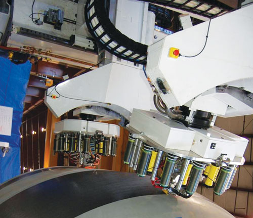
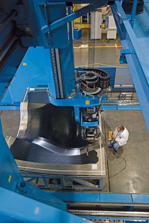
Goodrich Aerostructures used to rely on manual fiber placement in the manufacture of the inner fixed structure for the GEnx and Rolls-Royce Trent 1000 engines used on the 787 (see inset). Goodrich is migrating to an Ingersoll dual-gantry, two-head AFP machine that Goodrich hopes will speed production and provide structures of consistent quality. The company has a similar contract to provide the same part for the Airbus A350 XWB. Source: Goodrich Aerostructures
Newcomer ElectroImpact first studied the strengths and weaknesses of AFP and decided that machinery uptime was critical to productivity. It then designed this dual-head AFP to maximize uptime and machinery efficiency. Source: Electroimapct
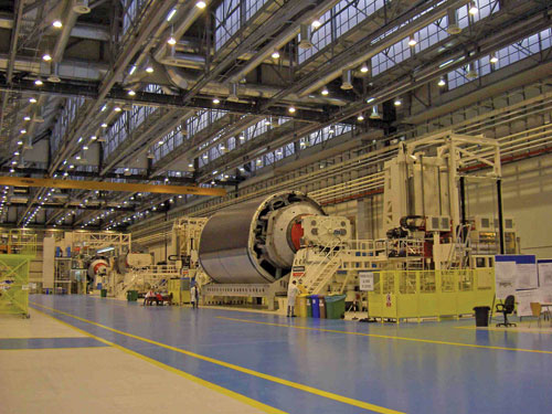
Alenia Aeronautica, a partner-supplier to Boeing for the 787, uses a massive Ingersoll tape layer to produce Section 44 of the Dreamliner fuselage. Tape layers are ideal for long courses that allow machinery to reach maximum speed. Most fiber placement projects, however, require a larger quantity of short courses, which is where AFP excels. Source: Ingersoll Machine Tools
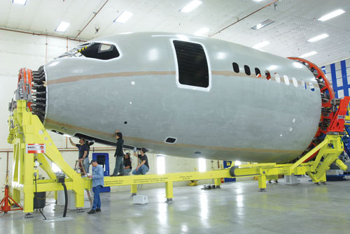
At least one ElectroImpact machine will soon be used by Spirit AeroSystems to manufacture the forward fuselage section of the Boeing 787 Dreamliner (inset). ElectroImpact believes that AFP could become the preferred method for automated placement processes. Source: Electroimapct
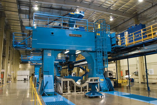
Software and hardware advances associated with automated tape laying (ATL) and automated fiber placement (AFP) equipment, such as this AFP system developed by Ingersoll Machine Tools, have enabled the production of large, carbon fiber-reinforced structures that previously were simply unattainable. According to AFP/ATL machine manufacturers, even more changes are on the way. Source: Ingersoll Machine Tools
Source: Goodrich Aerostructures
In the July issue of HPC we explored current machinery offerings from suppliers of automated tape laying (ATL) and automated fiber placement (AFP) equipment (see "Learn More," at left). In the last decade, software and hardware advances associated with these critical composites manufacturing processes have enabled the production of large, carbon fiber-reinforced structures that previously were simply unattainable. As a result, ATL and AFP equipment has enabled the development of The Boeing Co.'s (Seattle Wash.) 787 Dreamliner and will soon make possible the manufacture of Airbus' (Toulouse, France) forthcoming A350 XWB as well as a host of other applications in aerospace and other high-performance markets, where manufacturers are eager to take advantage of the speed and accuracy these systems can provide.
As is true in much of the composites industry, however, ATL and AFP- despite the technical strides of the last few years — are still experiencing tremendous change. The question facing suppliers and processors today is how placement technology will continue to evolve and where that evolution will lead the composites industry. HPC talked to several suppliers and users of ATL and AFP equipment and compiled the following report.
ATL vs. AFP
Conventional wisdom says that AFP, be-cause tows are narrower and more easily manipulated than tape, is most effective when placing material on a curved or contoured surface. It is limited by the number of tows allowed, the total width of those tows and the length of the courses being placed. The same conventions dictate that ATL is most effective when placing large amounts of material over a relatively large flat or minimally contoured surface, and it provides high-speed laydown in such an environment. However, a large, flat surface, even if it allows for large sections of continuous tape, almost always re-quires the strategic placement of shorter courses of tape or fiber in a variety of different locations.In practice, it has been generally assumed that ATL will be the speedier of the two processes if parts exhibit little complexity or surface irregularity. Randy Kappesser, VP/GM of MAG Cincinnati (Hebron, Ky.), which makes AFP and ATL machines, notes that ATL, when first introduced in the 1980s, was asked just to get the material onto the tool. Then, it had to do so reliably. Now, he says, "the focus is on productivity. It's all about pounds per hour." AFP, ostensibly the slower process, is assumed to be the better choice for parts where duplication of complex contours outweighs the need for production speed.
There are some signs, however, that this thinking might be changing as new material, hardware and software technologies allow the use of fiber and tape systems in new and unconventional ways. In this fluid, changing environment, suppliers are developing ATL and ATP systems that prove there is more evolution to come.
AFP ascendant?
ElectroImpact Inc. (Mukilteo, Wash.) is a relative newcomer to the automated fiber placement market, having developed its machinery primarily since 2003. The company's chief engineer, Peter Vogeli, says the foundation of ElectroImpact's technology grew out the company's analyses of the fiber and tape placement processes, assessing the ability of each to quickly and effectively produce parts. What ElectroImpact has discovered has helped shape the company's business plan and led the firm to focus exclusively on fiber placement, using a modular head concept that focuses on maximizing productivity.Vogeli says his company has discovered that while most projects have some long courses, at which ATL clearly excels, all projects are dominated by shorter courses. "You'd be shocked at how short the average course is for a part," he says. "Even the largest parts out there have very short course lengths." Average course length, he says, is usually no longer than 2m/6.5 ft. "Conceptually, many structures have long courses, but when it comes to designing, there are thickened sections and other variations that demand shorter courses." For example, notes Vogeli, on the nose fuselage section of the 787 Dreamliner, built by Spirit AeroSystems (Wichita, Kan.), only eight courses run continuously along the full length of the fuselage. The remaining 70 courses are much shorter and are designed to accommodate window openings, antennae, and other features.
"Part design drives a lot of things," explains Mag Cincinnati's Kappesser, pointing out that a highly contoured part will require narrower tape or smaller tow and will take longer to produce.
Although it is the slower process, automated fiber placement, according to Vogeli, achieves greater precision than ATL equipment and, thus, is best suited for short courses and patterns that demand a machine to be able to change fiber band widths quickly to accommodate a variety of design requirements. Speed, however, is not a variable easily separated from the others involved in ATL and AFP.
Although AFP clearly outperforms ATL in terms of the complexities of short course placement, Vogeli points out that there is nevertheless room for improvement in production speed. As courses get shorter, an AFP machine spends proportionally more time completing tasks that are not directly involved in the placement of fiber on the tool: accelerating and decelerating through the course, cutting fibers at the end of a course and turning around before beginning the next row of fiber placement. Another factor is machine stoppage. When the width of the fiber course (number of tows) or the fiber type needs to be changed, even more valuable production time is lost. "What we need to do is recognize that downtime is really significant on fiber placement machines," Vogeli contends. Conversely, ATL's proclivity for long courses and higher speeds is not as dependent on uptime for productivity. Because it lacks the raw speed that ATL provides, AFP must emphasize uptime as its most critical measure of machinery productivity.
The question is whether or not AFP can, eventually, bridge the speed gap and ultimately provide the greatest overall productivity, considering both laydown and scrap rates. "There's much disagreement in the aerospace industry about this, but I think the deposition rates of fiber will be as good as tape rates," he contends, thanks primarily to the ability of AFP machines to lay down 24 and even more tows in a single course. "The real difference will be scrap rates," Vogeli believes. The scrap rate when using tape, he says, can reach 30 to 40 percent because the machine must cut the end of each tape to trim it to fit the next course.
In a similar camp is David Champa, U.S. director of marketing for ATL manufacturer MTorres (Santa Ana, Calif.). Speaking at the Society of Manufacturing Engineering's (SME) Composites Manufacturing conference in April, he reported that both Boeing and Airbus have identified AFP as the most productive solution for fuselage skin lamination. Champa, while noting that ATL has traditionally been used to build wingskins because it was assumed to be the faster process on those relatively flat surfaces, suggests that AFP can and is challenging that assumption and should be considered for use in producing not only wingskins but stringers and spars as well.
In its analysis of test stringers produced using AFP, MTorres found that because the parts were composed chiefly of long, narrow ply shapes layed down in short courses, the parts were ideal for fiber placement. The result was higher productivity and a scrap rate one-third to one-quarter that of ATL. Similarly, when AFP was tested in production of flat skins, the process proved to be more efficient than ATL and generated one-half to one-third of the scrap. Champa notes that rules and guidelines of AFP and ATL use are changing rapidly and that shape alone no longer dictates whether AFP or ATL is chosen. It is not possible, he says, to use past business case standards in new programs.
At Forest-Liné (Paris, France), which makes ATL and AFP machines, Patrick Rousseau, senior composite project manager, notes several factors currently working in tape's favor: handling one piece of tape is easier than handling 32 tows of fiber; fiber tows break more easily than tape; and he believes that fiber placement systems, in general, are not as reliable as tape systems today. However, he says, if any of these benefits of ATL become compromised because of advancements in AFP, he foresees a greater ascendancy for AFP. Plus, he notes that a fiber placement machine can build any part a tape layer can but a tape layer can't build every part a fiber placement machine can.
ROI and the need for speed
Setting aside the ATL vs. AFP debate, any processor that considers adoption of these processes will find two relatively large barriers to entry when it comes to integration of either into its composites manufacturing environment: high cost and a formidable learning curve. The capital investment in an ATL or AFP machine, depending on size and capability, can range from a few hundred thousand to more than a million dollars. Vogeli points out that a Tier 1 aircraft manufacturer can spend $10 million to $12 million (USD) on a fuselage mandrel, plus $10 million to $15 million on the machinery to manipulate the mandrel and place the carbon fiber. On top of that, each technology requires massive knowledge acquisition: Designers must learn to design structures that work and integrate with ATL and AFP software, engineers must learn the fundamentals of automated fiber and tape placement and how it works with the design, while machine operators must be trained to use the equipment.Negotiating these education barriers involves hands-on experience, which takes time and inevitably involves production of flawed parts, particularly during the earliest and steepest portion of the learning curve. For these reasons, any decision to adopt ATL and AFP must be preceded by a realistic and careful analysis of the actual cost of acquisition (including downtime and waste during the learning curve) and a careful calculation of the effects that upfront and after-acquisition costs, savings realized as a result of the technology's use, and expected payback time will have on the company's return on investment (ROI). For all of the capabilities of ATL and AFP, every processor must evaluate the structures on which the technology will be used, taking into consideration the part's size, volume, complexity and application as well as ply requirements and other variables that influence process selection.
Rousseau believes that the future of ATL and AFP will be tied to designers. Speed likes long courses, he observes, but designers like short courses that enable them to place fiber only where needed to save weight. He adds, however, that the designer's preference for shorter courses does not mean that ATL and AFP processes will migrate to production of smaller parts. "There are just too many other processes, like RTM and vacuum infusion, that show promise and are better suited to small-parts production," he says. "I expect fiber and tape placement will continue to be used in the production of relatively large parts."
Ultimately, part design and process compatibility boil down to one over-riding variable that is central to the viability of any automated composites manufacturing process: speed. But not machine speed. Instead, it depends on the speed or rate of actual material laydown, which encompasses downtime, the impact of short vs. long courses and other variables that affect production efficiency. When carbon fiber plies are hand layed, the most capable worker has difficulty exceeding a laydown rate of 2.5 lb/hr. Mike Blair, VP of business development at ATK (Brigham City, Utah), made some waves in aerospace circles in 2007 when he announced at the SME Composites Manufacturing conference in Salt Lake City, Utah, that ATK would like to see AFP machinery achieve a consistent laydown rate of about 25 lb/hr to meet his company's ROI goals. At the time, he reported, ATK had AFP laydown rates of about 5 lb/hr, with near-term improvement to 14 lb/hr on the horizon. For ATL, he said the company is targeting, eventually, a 60 lb/hr laydown rate.
As for the 60-lb/hr ATL laydown rate, MAG Cincinnati's Kappesser says, "That's a place we'd like to get to, but a lot of that depends on the part." Yet Tino Oldani, president and CEO of Ingersoll Machine Tools (Rockford, Ill.), which makes ATL and AFP equipment, already has established rough benchmarks of current AFP speed capabilities: 50 lb/hr for a cylindrical part of 240 inches in diameter, or for a wing or a stabilizer panel (32 tows of width 0.5 inch/12.7 mm); 15 to 25 lb/hr for a part built in a complex female tool.
When it comes to speed, the biggest opportunities for improvement are available with the large parts — fuselage and wing skins, wing boxes, tail skins — that have been the focus of much AFP/ATL work over the last five years. This low-hanging fruit, however, has been well picked, and even on an aircraft like the 787 or A350 XWB, there remain few obvious and large candidates for conversion from metal to composites. In fact, the future of ATL/AFP could be headed more toward smaller, more complicated applications and structures, like engine cowls, nacelles, stringers, and airframes.
"What we see today is only the tip of the iceberg," says Oldani. "Fiber placement is still applied to parts that are relatively 'easy' and, almost exclusively, in the aerospace industry. The near future will bring many leaps forward that will make the fiber placement process the manufacturing process of choice. Airplanes will be designed by exploiting the characteristics of the carbon fiber and not using it as a black aluminum."
Forest-Liné's Rousseau cites several variables that he thinks have the greatest impact on speed of tape or fiber laydown productivity: average tape course length, prepreg behavior, and having a robust process. "Usually tape courses are not long enough to let you use all of the speed in your tape layer." Prepreg behavior during laydown relies most of all on how well the machine copes with tackiness of the tape and resin buildup on different machine components and how easy it is for operators to clean accumulated resin from those components and maintain them free from buildup. Predictability of the process harkens back to average course length: as courses shorten, a machine's ability to manage acceleration, deceleration and jerk (changes in acceleration) is critical to overall process speed.
Manual-to-automated conversion
One notable and recent example of AFP's capabilities can be seen in a manual-to-automated process conversion that is taking place at Goodrich Aerostructures (Chula Vista, Calif.). The thrust re-verser inner fixed structure (IFS) is manufactured at its Riverside, Calif., facility for the GEnx engine and the Rolls-Royce Trent 1000 engine used on the 787. Each IFS, which provides the air wash surface for the engine thrust reverser, measures about 120 inches wide by 96 inches long by 40 inches deep (3,048 mm by 2,438 mm by 1,016 mm). The part is layed up in a concave-shaped tool the surface of which features a variety of complicated contours. One engine uses two IFSs; therefore, each plane requires four."We're not winding a barrel. We're going inside a concave surface," says Jeff Rogers, VP of new programs/product and process design at Goodrich, of the female tool. "The head has to be much smaller than what you'd find on a 787 fuselage partner machine. It has to be more nimble to work in tight spaces and corners." Rogers says the most challenging aspect of the structure and its tool are its compound contours.
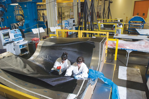
Until a few months ago, Goodrich had been manufacturing these structures by hand, a process that required employees to crawl into the tool to lay up some of the carbon fiber fabric plies. Rogers says the company considered the ergonomic challenges of having employees crawling inside a 12,000-lb tool and also did the math on output requirements, and they realized quickly that a manual layup process would not meet the volume target of 40 inner fixed structures per month set by Boeing. Plus, Goodrich has won a similar contract to produce the IFS for the A350 XWB. "What's driving us is cost targets," says Rogers. "We had a real case for action just looking at our combined volumes."
Goodrich started first by evaluating machine type — gantry-type vs. moving tool-type AFP systems — and opted for two Ingersoll 8-axis machines that are configured in a dual gantry layout in which they share a common rail. The first machine was installed in spring 2007, followed by the second in April of this year. Although the manufacturing process is still being fine-tuned, the two machines will work together to produce an IFS: One AFP builds the outer skin, placing in the female tool 0.125-inch/3.18 mm wide tows comprising HexTow AS4 prepregged carbon fiber/epoxy supplied by Hexcel (Dublin, Calif.). This skin is cured at 350°F/170°C in an in-house-built autoclave. Next comes installation of a honeycomb core, adhesively bonded to the outer laminate. The other Ingersoll machine then places the inner laminate, using the same HexTow material, followed by another cure cycle. The finished IFS is ~1.75 inches/~44.5 mm thick. Each machine can perform either of the two tasks and, working simultaneously, they greatly increase part production.
Rogers says the cost of the machines has already been justified. "From a quality standpoint, it's going to be a more consistent-quality product coming out of the machine," he says. He adds that Goodrich is evaluating other parts, such as fan cowls, that could be made via AFP.
Despite the massive strides made by ATL and AFP over the last decade, it's clear that these high-speed machines have much room to grow to meet the evolving demands of high-performance composites production. The next five years or so are likely to reveal much about how AFP and ATL will be im-proved, where they will be used and which machine type, if any, will establish itself as the preferred technology.


Related Content

Materials & Processes: Resin matrices for composites
The matrix binds the fiber reinforcement, gives the composite component its shape and determines its surface quality. A composite matrix may be a polymer, ceramic, metal or carbon. Here’s a guide to selection.
Read More
MFFD thermoplastic floor beams — OOA consolidation for next-gen TPC aerostructures
GKN Fokker and Mikrosam develop AFP for the Multifunctional Fuselage Demonstrator’s floor beams and OOA consolidation of 6-meter spars for TPC rudders, elevators and tails.
Read More
RUAG rebrands as Beyond Gravity, boosts CFRP satellite dispenser capacity
NEW smart factory in Linköping will double production and use sensors, data analytics for real-time quality control — CW talks with Holger Wentscher, Beyond Gravity’s head of launcher programs.
Read More
Materials & Processes: Fabrication methods
There are numerous methods for fabricating composite components. Selection of a method for a particular part, therefore, will depend on the materials, the part design and end-use or application. Here's a guide to selection.
Read MoreRead Next

Composites end markets: Energy (2024)
Composites are used widely in oil/gas, wind and other renewable energy applications. Despite market challenges, growth potential and innovation for composites continue.
Read More
CW’s 2024 Top Shops survey offers new approach to benchmarking
Respondents that complete the survey by April 30, 2024, have the chance to be recognized as an honoree.
Read More