
Are Hybrid Designs the Future for Composite Bridge Decks?
Teaming composites with traditional materials may be the future direction for cost-effective infrastructure replacement.


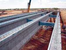
Source: University of WisconsinThis bridge in Waupun, Wis. is the first to use composite reinforcing elements in a concrete bridge deck supported by prestressed concrete girders.

Source: University of Southern QueenslandThe Coutts Crossing Bridge in New South Wales, Australia has one segment made from fiberglass and carbon box beams with a polymer concrete cap and wearing surface.
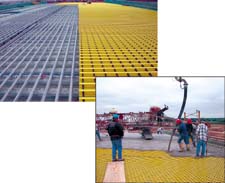
Source: University of WisconsinBack picture: Composite rebar from Hughes Bros. and a pultruded bidirectional bar grid from Strongwell are installed over the forms. Note the coarse limestone aggregate already in place on the forms, the key to good adhesion between the forms and the deck concrete. Front:The concrete is poured into the composite-reinforced deck. The pour was faster on the composite bridge deck, compared to the conventional deck, saving labor cost and time.
More than 25 percent of all highway bridges in the U.S. are considered deficient today, unable to handle traffic loads and meet basic safety standards. The biggest contributor to bridge deterioration is corrosion - if the concrete cracks, water can contact the reinforcing steel, which causes it to rust. As rust develops, the degrading steel expands, exerting pressure on the surrounding concrete, causing more cracking, greater water intrusion and increasing rust, in an escalating cycle of destructive cause-and-effect.
Composite bridges have been advocated as a means to break this cycle of deterioration in aging infrastructure, based on proven corrosion resistance, light weight and speed of installation. Yet, while many composite bridges are in place and functioning well (see "How Are Composite Bridges Performing?" in CT December 2003, p. 16) the pace of installation has slowed significantly. Engineers and departments of transportation still are not comfortable with all-composite designs. In addition, it is likely that up-front material costs for composite decks always will be higher than the costs of traditional materials. Further, new high-performance concrete admixtures and high-strength steels now make traditional concrete replacement decks look more attractive.


While composite reinforcing bars and grids have been used as a substitute for steel for years, a promising solution is to combine one or more composite elements together with concrete, to achieve a bridge deck system with the best characteristics of each type of material. The composites can be used to impart lightweight and corrosion-free reinforcement appropriate for the application, yet the design also can retain the very low cost and the traditional techniques of concrete construction. In addition, the greater ease of handling and faster installation that results from using composites can reduce labor, making the overall capital cost of a hybrid deck comparable to a traditional deck.
"All-composite bridge decks were the first generation," says Scott Hemphill, president of Hardcore Composites LLC (New Castle, Del., U.S.A.), whose company made many of the composite bridge decks now installed in the U.S. "Now our industry needs to evolve along with the construction industry and what the engineers and owners want. In my opinion, the next generation is some kind of hybrid approach."
In this article, CT take a look at three examples of hybrid deck system designs.
"Composite Action" for Composites
Recently, the hybrid approach was employed in twin bridges on U.S. Rte. 151, north of Waupun, Wis. by a team consisting of the Wisconsin Dept. of Transportation (DOT), the Federal Highway Admin. (FHWA), Alfred Benesch and Co. (Chicago, Ill., U.S.A.) and researchers from the University of Wisconsin (U of W). FHWA's Innovative Bridge Research and Construction (IBRC) program funded the project. To facilitate a cost/benefit comparison between the composite hybrid and conventional construction, the northbound deck was reinforced with composites, while the adjacent southbound deck was made with traditional steel-reinforced concrete, says U of W lead investigator Larry Bank. Both bridges are 12.75m/43 ft wide with two equal spans of 32.7m/107 ft, for a total length of 65.4m/214 ft. Decks are supported by five prestressed concrete girders, spaced at 2.6m/8.6 ft on center.
The composite-reinforced bridge incorporated three elements: 1) pultruded stay-in-place deck panels manufactured by Diversified Composites (Erlanger, Ky., U.S.A.) for Composite Deck Solutions LLC (Dayton, Ohio, U.S.A.); 2) standard fiber-reinforced plastic (FRP) rebar made by Hughes Bros. Inc. (Seward, Neb., U.S.A.) and 3) a bidirectional FRP pultruded bar grid manufactured by Strongwell (Bristol, Va., U.S.A.). The fiberglass/vinyl ester deck panels, 457 mm/1.5-ft wide by 2,350 mm/7.8-ft long, incorporate two hollow, square stiffening ribs that run the length of the panel's long dimension. Panels were designed to span the distance between the girders, but not meet at the center of the girder (thus explaining their shorter dimension). The panels form the lower tensile reinforcement for the deck in the transverse direction. Edges of the panels were overlapped by several inches, and a bead of silicon together with epoxy-coated screws held the panel's lapped joints together during construction, to contain the concrete. Black pigment was added to the HETRON vinyl ester resin, supplied by Ashland Specialty Chemical Co. - Composite Polymers Div. (Columbus, Ohio, U.S.A.), to give the panels better ultraviolet (UV) resistance, says Diversified's Lee Burch. To prevent concrete from flowing into the panels' hollow ribs, the rib ends were filled with polyurethane foam.
A key construction detail ensured good adhesion between the panels and the concrete poured into them. Coarse limestone aggregate was adhered to the panels with a coating of construction epoxy paste. Panel/concrete adhesion is critical to developing "composite action," a non-materials-related term used by civil engineers to describe the way the girders, the stay-in-place deck panel forms and the concrete work together to share the applied loads.
"The Waupun bridge is the first application of composites in a 'composite-action' bridge deck system, and the first to use composites with prestressed concrete girders," says U of W's Bank. A similar hybrid deck was installed by Composite Deck Solutions in Dayton, Ohio on the Salem Ave. bridge, but the support girders were steel.
Once the panels were installed and coated, composite rebar was placed in accordance with American Concrete Institute (ACI) standards. The rebar provided additional stiffness in the area of the bridge located over the center support pier, as well as temperature and shrinkage reinforcement elsewhere. Three rebar sizes were used - 13 mm, 19 mm and 25 mm (0.50 inch, 0.75 inch and 1 inch) diameter - all of which had a fine sand texture and a helical surface finish for improved bonding with the concrete.
The pultruded bidirectional grid was placed directly above the rebar. The grid consisted of 50 mm/2-inch deep I-bars spaced 100 mm/4 inches apart and was held together with pultruded 13 mm/0.5-inch round rods running through holes drilled in the bars. The grid sections, oriented with the I-bars perpendicular to the underlying composite rebar, were held in place across the width and length of the deck with simple plastic connectors. The grid was designed as the top reinforcement in the deck, carrying tensile stress over the girders, says Bank.
Haunches were required for proper elevation of the stay-in-place forms above the girders, to maintain uniform deck thickness. The haunches, which elevated the composite deck panels slightly above the top flange of the concrete girders, were constructed of rigid polystyrene foam, attached to the edges of each girder with an epoxy adhesive (except for the outer girders, which had conventional plywood forms in place for the overhanging parapet). According to Bank, the design team was concerned that the poured concrete might not be able to flow into the gap between the tops of the girders and the bottom of the deck panels, to achieve permanent deck form support. To prevent this potential problem, the gap was filled with a flowable grout - essentially neat concrete without reinforcement - that was cured prior to the pouring of the main concrete deck.
The construction documents included special provisions that defined specifications for the three different FRP materials, following a model recently developed for the FHWA by U of W and others. The specifications required each material manufacturer to submit certified test reports, confirming that the parts possessed the defined strength, stiffness and physical properties. In addition, U of W conducted quality assurance trials on representative material samples, including tests for longitudinal tension, longitudinal short beam shear, fiber volume fraction, water absorption, dimensional tolerance and aggregate distribution. Once satisfactory test results were received, the materials were approved for use by the construction engineer. Bank notes that performance testing capability is a must for composite material suppliers who wish to participate in infrastructure projects. "We believe that testing should be written into the project specifications," he says. "It's important to the DOT, and ties in with the FHWA's goal for standard specifications for composites in highway and bridge construction."
The concrete pour commenced at 6:00 a.m., June 11, 2003 and was completed four hours later. Standard concrete was used, but with maximum 0.75-inch diameter aggregate rather than the usual maximum 2-inch aggregate, to ensure that the concrete would flow through the grid and into the formwork. "The composite I-bar grid is very stiff and would not bend to form the center crown," says Bank, "so an additional inch of concrete had to be poured to allow for the required top cover at the bridge's center, over the support pier."
The final material tally for the composite-reinforced bridge was $632,718, compared with the cost of the steel-reinforced bridge at $419,566. The cost of the composite elements was $164,970 for the deck panels, $66,150 for the grid and $22,950 for the rebar, for a total of $254,070 as compared to the cost for the steel reinforcement at $36,401. But, all of the composite components were light enough for one or two construction workers to carry and put in place, a factor that accelerated construction of the composite-reinforced deck. "Several workers commented on the ease of working on the level composite grid as opposed to the uneven rebar on the steel-reinforced deck," says Bank.
Installation and removal of the concrete formwork on the steel-reinforced bridge consumed 585 man-hours, while only 206 man-hours were required to place the composite panels and foam haunches in position on the composite-reinforced deck. Further, the steel grid was in place after 128 man-hours, but the composite rebar and grid took only 104 hours. The concrete also poured more quickly on the composite deck, at a rate of 44.7 m³/58.5 yd³ per hour compared to 29 m³/38 yd³ per hour for the steel-reinforced deck. The quicker pour was likely a combination of the smaller aggregate size and the fact that the composite grid made an easier and more efficient work surface, comments Bank.
The project was completed successfully, according to Bank, because of close communication between the designers, material suppliers, owners, the construction project manager, CH2M Hill, and the bridge construction company, Lunda Construction. "Coordination of all parties is absolutely critical, because composite products require innovative thinking that may be different from conventional design details," he says.
Both bridges will be tested under service loads over the next five years, using strain gauges installed on various parts of the composite grid and deck panels and comparable components on the steel-reinforced span. Because he believes the tests will confirm that the composite design not only offsets the higher up-front material cost and speeds construction but also improves deck durability, Bank concludes, "Composites can play an important role in enhancing the current technology. With this project, we get the best of both worlds. We're hopeful that this will inspire other, similar bridge projects."
Alternative Design Down Under
Another hybrid design prototype was developed, put into service and has proven to be exceptionally durable under heavy truck traffic at a rock quarry in New South Wales, Australia - the first Australian vehicular bridge to incorporate composite materials. Researchers at the University of Southern Queensland (USQ) collaborated on the project with the Queensland Dept. of Main Roads, the Roads and Traffic Authority New South Wales and Wagners Pty. Ltd. (Toowoomba, Queensland, Australia). USQ's Prof. Gerard Van Erp explains that the initial design concept featured a traditional concrete beam reinforced with steel. "The main disadvantages of steel-reinforced concrete are the potential for corrosion and the high self-weight," says Van Erp, explaining, "When you look at the fact that 75 to 80 percent of the material that contributes to the weight - that is, the concrete itself - does not directly contribute to the load-carrying capacity of the beam, it's an inefficient and wasteful design."
Rather than simply substitute FRP for steel reinforcement, however, Van Erp's team devised a 350 mm/14-inch wide, 450 mm/18-inch deep hollow fiberglass/polyester pultruded box beam with a 100 mm/4-inch thick concrete cap. Multiple beams, when arranged side-by-side and bonded together with epoxy adhesive into a single unit, are designed to function as both support girders and deck. The beam design incorporates unidirectional carbon fiber into the bottom or tensile flange. The carbon fiber was supplied by Zoltek Corp. (St. Louis, Mo., U.S.A.). Glass fibers are oriented at +45° and -45° in the vertical webs to carry shear forces in the beam and the top horizontal web. The top flange has a proprietary fiber architecture that imparts added compression capacity. Wagners Fibre Composite Technologies (a subsidiary of Wagners Pty. Ltd.) pultruded the hybrid beam cost-effectively in a single profile, at one-third the weight of a traditional concrete beam. Several fiberglass/polyester diaphragms are adhesively bonded inside the beam at the ends to help carry the loads from the beams into the bridge abutment foundations and prevent crushing of the box, says Van Erp.
The prefabricated concrete beam cap is reinforced with chopped polypropylene fibers for increased failure strength and functions as a compression flange, says Van Erp. The caps, which run the length of the beams, are poured and allowed to cure for several weeks, and then they are bonded to the composite beams with an epoxy adhesive.
"By design, the earliest signs of failure will be cracks in the concrete cap, a condition much easier to detect during inspection than cracking or delamination in the composite beam itself," explains Van Erp. "The beam can still carry additional load after crushing of the concrete, as a safety factor."
Extensive laboratory testing of beam prototypes showed that the hybrid beam has considerable excess strength, because the design was governed by a maximum deflection requirement of the span length divided by 500 under normal traffic loading. Even after the concrete cap crushed and failed during testing, the box still had an ultimate design moment capacity of nearly 700 kNm, at a deflection of 550 mm/22 inches. This overdesign is desirable in the face of traffic loads imposed by the all-to-frequent occurrence of overweight trucks in Australia, known as "road trains," particularly on rural roads.
In 2002, 14 beams were bonded together to form a plank-type bridge over a 10m/32-ft single span at the quarry operated by Wagners' parent company. A variety of heavy trucks were driven over the bridge, and strain gauges and deflection monitoring showed that the bridge handled the loads "extremely well," says Van Erp. At one point, a 75 tonne (165,000 lb or 82 ton) fully loaded mining truck was driven over the span - a load nearly four times the legal limit for the bridge. Measured deflection was 18 mm/0.72 inch, consistent with modeled predictions. "This load would have to be increased by at least five times to approach the strength limit state of the structure," Van Erp maintains.
Since the quarry installation, a second hybrid-beam deck has been installed by Wagners Composite Fibre Technologies on an existing wooden vehicular bridge near Grafton in northern New South Wales. According to Van Erp, roughly one-quarter of the approximately 40,000 existing road bridges in Australia are of timber construction, the majority built prior to 1940. Natural degradation and increased loads from modern vehicles have, in many cases, reduced margins to unacceptable levels.
The composite beams replace one 12m/39-ft segment of the 90m/292-ft Coutts Crossing timber deck. Two sections of 10 beams each were joined along the center with bolts, to form a deck with a total width of 7m/22.75 ft and a slight crown. Four bolts hold the beams in place against the concrete abutment. "The bridge is very light and wants to float when submerged, so we employed the bolts in the eventuality of a flood," says Van Erp.
The material cost for the hybrid beam bridge segment was about twice that of a traditional steel-reinforced concrete bridge deck. However, the deck installation, which included removal of the old timbers, took only five days, resulting in a shorter road closure and lower labor costs, which effectively made the bridge less expensive, says Van Erp. "We expect this new concept to play a major role in Australia's bridge replacement program."
More to Come?
Perhaps the most high-profile hybrid composite/concrete concept is the long-awaited I-5/Gilman Advanced Technology Bridge at the University of California, San Diego (UCSD). The concept, which first emerged in late 1993 and since has undergone several redesigns, will span Interstate 5, to connect the two segments of the UCSD La Jolla campus. Construction may begin during summer 2005, following a prototyping phase.
If built, the I-5/Gilman bridge will be steel cable-stayed with an eccentric (off-center) pylon support (current plans call for a few of the cables to be made with carbon fiber). Pylon legs will be filament-wound carbon fiber/epoxy tubes, filled with concrete. Two concrete-filled, filament wound longitudinal carbon fiber/epoxy tubes will support the deck. According to UCSD's Prof. Frieder Seible, who heads the project, the concrete provides compression force transfer, stabilizes the thin shell against buckling and allows for the anchorage of connection elements.
The two longitudinal tubes will support transverse E-glass and carbon-reinforced pultruded hollow box beam girders. The girders, in turn, will support composite stay-in-place panels, which will snap into place in composite stirrups on the girders. The panels will support a poured deck of concrete reinforced with polypropylene fibers. CT will continue to follow the I-5 project and other hybrid projects and report on new developments.
"If the composites industry wants to be in the bridge construction business, there is low-hanging fruit out there," says Hardcore's Hemphill. "Hybrid projects give us a chance to introduce composites in value- and time-saving ways."


.jpg;maxWidth=300;quality=90;format=webp)

Related Content

Henkel receives Airbus qualification for European aerospace manufacturing facility
The adhesive company’s Montornès, Spain, plant has been approved as a standard and raw materials supplier for various Airbus platforms, adding to its work in lightweighting, fuel efficiency and automation.
Read More
Pro-Set named official materials supplier for New York Yacht Club American Magic
Competitive sailing team prepares for the 37th America’s Cup beginning in August 2024 with adhesives, resins and laminate testing services for its AC75 monohull construction.
Read More
Scott Bader ATC begins Crestabond MMA structural adhesive production
Scott Bader’s Drummondville, Canada, facility has begun manufacturing and supplying composites-applicable adhesives to its North American customers.
Read More
Scott Bader acquires Satyen Polymers, enhances commitment to Indian customers
Under the agreement, India-based Scott Bader Pvt. Ltd. will assume responsibilities for direct sales and marketing for all resin and gelcoat products, bring composites and adhesives to Indian market.
Read MoreRead Next

Composites end markets: Energy (2024)
Composites are used widely in oil/gas, wind and other renewable energy applications. Despite market challenges, growth potential and innovation for composites continue.
Read More
CW’s 2024 Top Shops survey offers new approach to benchmarking
Respondents that complete the survey by April 30, 2024, have the chance to be recognized as an honoree.
Read More
From the CW Archives: The tale of the thermoplastic cryotank
In 2006, guest columnist Bob Hartunian related the story of his efforts two decades prior, while at McDonnell Douglas, to develop a thermoplastic composite crytank for hydrogen storage. He learned a lot of lessons.
Read More