
Fair winds for offshore wind farms
Innovations in blades, turbines and foundations are helping spur growth in a very big way.

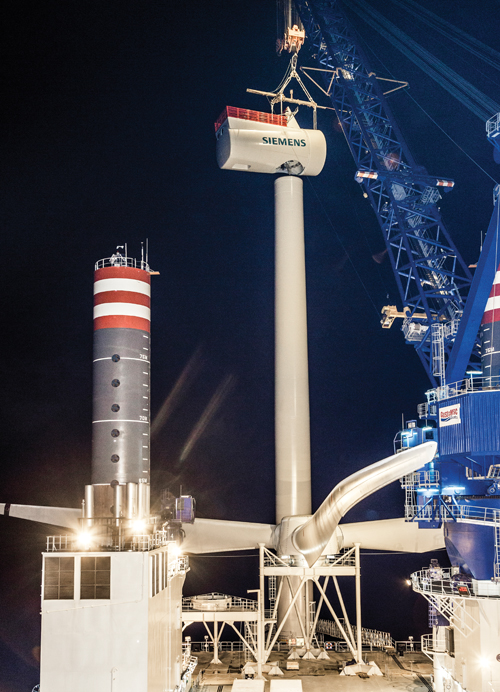
Siemens (Munich Germany) recently installed this new 6-MW turbine in the English Channel for testing. Its lightweight, all-glass 75m/244-ft long blades from Siemens are molded in one piece. New turbine and blade improvements are making mammoth blades more manufacturable. Source: Siemens
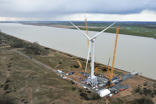
LM Wind Power supplied the 73.5m/240-ft long blades for this Alstom (Paris, France) 6-MW Haliade offshore turbine, shown here during tests near the shoreline at Carnet, France. The new turbine/blade combo will be deployed in three wind farms offshore of France. Source: Alstom
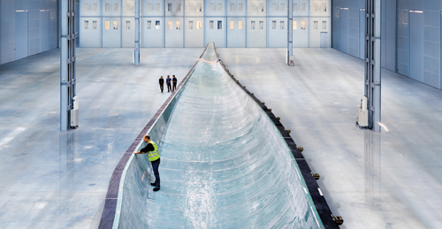
Siemens produces its one-piece 75m/244-ft megablades in a one-shot closed molding process. One half of the massive mold tool is shown here. Source: Siemens

A 75m blade, in transit over public roads. Blade Dynamics (Cowes, Isle of Wight, U.K.). hopes to make blade transport less burdensome with its segmented approach to blade construction. Source: Siemens


Despite economic and political uncertainties, weakening investments, grid connection issues and a dip in the U.S. onshore wind energy market, offshore wind around the world continues its momentum. The European Wind Energy Assn. (EWEA, Brussels, Belgium) says 132 offshore wind turbines in 13 wind farms (523.2 MW of capacity) came online in the first six months of 2012 — an increase of 50 percent from the same period in 2011. EWEA also reports that as of June 2012, 4.3 GW of offshore turbines had been installed off the European coast, and conservative estimates are that the total could grow to 25 GW by 2020. In Japan a huge new 1-GW offshore wind farm — the world’s largest to date — was announced in January to replace the nuclear power capacity lost in the March 2011 earthquake and tsunami. Although the U.K. (the world’s leader in installed offshore units), Germany, Belgium, France and Italy lead the offshore surge, China’s offshore wind industry is reportedly poised for huge growth. Moreover, Morocco and Tunisia have active developments, and in 2014, Egypt will begin work on a 200-MW wind farm in the Gulf of Suez. In fact, the offshore wind analysts at 4C Offshore (Suffolk, U.K.) are tracking 1,301 offshore wind projects in 38 countries with a total nameplate power capacity of 3.6 GW (for more information, see first editor's note at the end of this article).
What is propelling this growth? The Global Wind Energy Council (GWEC, Brussels, Belgium) cites offshore wind’s as-yet unrealized potential and its advantages over land-based wind systems. The latter include higher wind speeds, less turbulence, fewer environmental constraints and the fact that most urban centers are located on coastlines. In the U.S., for example, Cash Fitzpatrick, an energy R&D engineer with the U.S. Department of Energy’s (DOE) Wind and Water Power Program, says, “Twenty-eight coastal and Great Lakes states use 78 percent of the U.S.’s electricity. We project the U.S. offshore wind market to grow substantially and reach $2 billion by 2020.”


Growth, however, will require belt tightening and technical innovation. The GWEC points out that offshore technology is still new enough to present significant opportunities for both. Indeed, market analyst Dan Shreve of Make Consulting (Chicago, Ill., and Boston, Mass.) warns against business as usual: “Traditional wind turbine designs have their limitations, and continued evolution of an existing design will eventually lead to diminishing returns,” he says. “In order to expand the market of current low-wind-speed turbines into higher-speed wind environments, innovation is required, and innovation requires investment — which is sometimes difficult to justify in a difficult market environment.”
Cost-saving innovations, in fact, are already proliferating, and many center around composite materials. New blade and turbine designs include segmented blades and pultruded spars. Notably, floating systems are already in the works to enable affordable turbine installations over deep water.
Still betting on behemoth blades
Perhaps the best-known design driver for wind blades is the fact that an increase in blade length nets a fairly dramatic increase in swept area and, therefore, energy capture. “There is no upper bound on the size of offshore turbines,” Fitzpatrick points out. “We can foresee a 10-MW machine or even, eventually, a 20-MW machine. The sky’s the limit.”
Blade mass (and cost), however, grows at a faster rate than energy production. But blade manufacturers have not let the challenges of scale stop steady progress toward bigger offshore blades, despite transportation issues, manufacturability and the sheer volume of materials required. Material-based measures can be taken to reduce the growth of blade mass, such as replacing glass fiber with lighter, stronger carbon fiber (see "Wind turbine blades: Glass vs, carbon fiber," under “Editor's Picks,” at top right). But longer, leaner blades also can be produced by optimizing designs and streamlining manufacturing processes.
Todd Griffith, a researcher in the Analytical Structural Dynamics department at U.S. energy technology incubator Sandia National Laboratories (Albuquerque, N.M.), has been involved in a study to develop ultralong blades for a theoretical 13.2-MW horizontal axis turbine. At lengths of 100m/325 ft or more, the blades would be significantly longer than any commercial blade produced to date. Using geometric scaling models and conventional aerodynamic shapes, Griffith and his team developed a “baseline” 100m all-glass blade (SNL100-00) as a starting point to investigate design tweaks that might reduce mass and improve aerodynamic performance.
According to Griffith, the baseline design, with a reported mass of 114,172 kg/251,178 lb, exhibits tip deflections and spanwise strains that are within specifications, verified by Sandia’s NuMAD finite element modeling blade code, and satisfies all international design standards for loads and materials — clearly demonstrating that all-glass blades are feasible even at this extreme length. “There are promising design opportunities, such as changes in airfoil architecture and material lay-ups, jointed blade designs, load alleviation concepts and blade platform innovations, that we plan to evaluate to overcome the logistical challenges of these very large blades,” says Griffith.
LM Wind Power (Kolding, Denmark) has always relied on all-glass designs, and its 73.5m/240-ft long blade, currently the world’s longest, was developed in collaboration with Alstom Group (Paris, France) to power Alstom’s new Haliade 150, a 6 MW offshore turbine. Alstom broke ground on Jan. 21 for the first of two manufacturing facilities in France, near the project site. One, within the harbor zone of Saint-Nazaire, on the west coast of France, will produce turbine components and nacelles. Alstom says the site will turn out 100 turbines per year. Ground will be broken on a second complex in Cherbourg on the northern coast next year. Blade and tower production will begin there in 2016 at a rate of 100 sets per year.
The 6-MW Haliade, capable of supplying power to 5,000 homes, employs a gearless direct-drive design that diverts unwanted bending stresses from the blades directly into the tower and reduces the number of moving parts for better reliability.
Alstom collaborated with LM Wind Power’s blade designers, says Alstom’s offshore platform director, Daniel Castell, “to design a blade specially for the Haliade to optimize the power production.”
LM Wind Power’s VP of sales and marketing, Ian Telford, notes, “Our technology enables us to design and manufacture a relatively lighter glass fiber/polyester blade for the length, and we have been able to handle the industrialization of these blades, which is not easy.” The 73.5m blade is an outgrowth of LM’s new GloBlade research program. It has an optimized, thinner aero profile and proprietary “innovative features” developed after extensive wind tunnel testing and validation. (See, for example, “Redefining the root,” below.) Its larger swept area captures as much as 14 percent more energy than older blades.
After several rounds of in-house testing, the LM design was installed on a prototype Haliade turbine located onshore in Le Carnet, near Saint-Nazaire, and tested at full power throughout 2012 by Alstom (see “Learn More”). Data were collected to verify models and design specifications. According to Alstom, the Haliade blade and turbine combination, with a rotor diameter of 150m/488 ft, generates 40 percent more electricity per kilogram of material than existing offshore turbines and will improve annual energy production by 15 percent, compared to existing offshore farms. A second offshore installation of the Haliade will occur in mid-2013 in the Belwind wind farm near Ostend, 45 km/28 miles off the coast of Belgium, at a depth of 35m/114 ft.
Although Alstom’s offshore installations will be on fixed platforms in relatively shallow water, the company has been considering how to tackle deepwater wind for many years. It has collaborated on R&D with others, including the Massachusetts Institute of Technology (MIT, Cambridge, Mass.), on floating turbine platforms for deeper water in the Atlantic and, possibly, the Mediterranean Sea. Alstom’s Castell says, “We are definitely considering the use of composite materials in our floating foundation design.” Although design details have not been revealed, the target for installation of a floating prototype is mid-2015.
Production innovations for even bigger blades
On Oct. 6, 2012, trials began at a test station in Østerild, Denmark, for another big, all-glass blade built by Siemens (Munich, Germany) for the company’s new SWT-6.0, a 6-MW offshore wind power turbine. On a three-blade rotor, the 75m/244-ft B75 blades will span 154m/500 ft, with a swept area of 18,600m2/200,200 ft2.
To produce the B75, Siemens uses its patented IntegralBlade process — which infuses the entire blade, including the root and integral spar, in one shot, within a closed mold — to create a blade without any bonded joints (see “Learn More”). An inflatable bladder produces consolidation pressure inside the mold during cure. Materials include glass, epoxy resin and balsa core. “Blades produced in this manner are extremely robust, which significantly improves the cost efficiency of wind turbines,” says R&D manager Christian Hvejsel. “They have to withstand very high loads and moments.”
Air loads range as high as 200 metric tonnes (440,925 lb) at a 10m/32.8-ft-per-second wind speed. Siemens’ patented QuantumBlade design process yields a blade that weighs 20 percent less than conventionally produced blades, claims Hvejsel. He says success is due, in part, to specially designed aero profiles shaped in a way that deliver maximum rotor performance under a range of wind speeds. As a result, nacelles, towers and foundations also can be made lighter to reduce overall facility cost. Says Henrik Stiesdal, the company’s chief technological officer of wind power, “With a larger rotor comes more energy, but also greater loads and more cost. It’s a matter of finding the right balance.”
The first two 6-MW turbines from Siemens (equipped with standard 60m/197-ft rotor blades) are now being installed and tested at the Gunfleet Sands III wind farm in the English Channel. During the next several years, DONG Energy (Fredericia, Denmark) plans to install 300 6-MW Siemens wind turbines, equipped with the B75 blades, in the U.K.
The longest wind turbine blade produced to date, at 83.5m/271 ft, comes from 12-year-old SSP Technology A/S (Kirkeby, Denmark). The massive blade was developed for Samsung Heavy Industries’ (Seoul, South Korea) newly announced 7-MW offshore turbine design, destined for an upcoming South Korean offshore project near Jeju Island.
“We are more unconventional than other blade producers,” says SSP CEO Søren Brouer of its modular approach in which the root and spar are fabricated separately then assembled with the blade shells in a resin infusion process. The company invented and patented its root and spar designs, which reportedly enable production of very long, yet strong, blades. “Our design allows a larger load with a smaller bolt circle diameter, which leads to overall cost savings,” adds Brouer (see “Redefining the root,” under "Editor's Picks").
The unconventional box spar concept is where most of the blade’s material is concentrated. “The aero shells are just profiles, since the spar does the work — it allows us to make the blade shells much lighter,” explains Brouer. The spar is fabricated separately in upper and lower female mold halves, with wide edge flanges, and it is built up using glass/epoxy prepreg and cored with balsa on the two vertical sides to enhance shear performance. The spar halves are joined with adhesive that’s applied along the overlapping flanges. Notably, one mold can be used to create a variety of spars for different customer blade designs, simply by changing the number of plies and the core thickness in the layup. The use of a female mold ensures that the spar cap has a smooth and precisely formed contact surface when it is bonded to the aero shells.
SSP also differs from other blade makers in that its molds are designed and produced in-house using a honeycomb-cored glass/epoxy prepreg sandwich construction. Because they weigh much less than a comparable metal blade mold, they can be turned and closed more easily, and no overhead cranes are required.
SSP lays up dry reinforcements in the shell molds, including prepreg materials in key areas, then places the already cured root joints and spars in the molds, closes the mold halves and then infuses the entire assembly with epoxy resin. The cured blade is then coated to customer specifications. For some applications, says the company, blades could be shipped in two halves and assembled on site, reducing transport costs.
SSP firmly believes that its modular approach enables faster processing and greater part quality, the latter because the coefficient of thermal expansion (CTE) of the composite tool is compatible with the CTE of the blade parts. Therefore, Brouer claims, “We are able to achieve very high part accuracy with very little post-cure finishing,” adding that for the 83.5m blade, the tolerance was ±0.5 mm/0.02 inch.
Breaking blades down?
In view of the fact that blades will inevitably get bigger, some advocate making blade production more manageable through segmentation. Although others question the need, several suppliers have moved ahead with practical designs, among them a U.S. start-up called Modular Wind Energy (Huntington Beach, Calif.) and a five-year-old U.K. firm called Blade Dynamics Ltd. (Cowes, Isle of Wight). The latter’s design and research center is in the U.K., but its main manufacturing facility is located at the former NASA Michoud Space Shuttle external tank assembly plant in New Orleans, La.
“It’s very hard to ensure quality and aerodynamic accuracy in these gigantic, full-length blades if they are molded at full length. Tooling costs become very high and transport [is] a logistical nightmare,” says Blade Dynamics’ senior technical manager, David Cripps. “We’re able to make all blade moldings in smaller, more cost-effective molds and assemble them, similar to an aircraft manufacturer, for improved part quality.”
The company’s segmented concept includes the box spar, which is made with carbon/epoxy. Its profile changes along the length of the blade. Although other details aren’t available, such as the length of each blade segment or precisely how each blade is fabricated then joined, Cripps reveals that assembly requires no mechanical fasteners (to avoid stress risers) and uses a “bonded approach” that is “perfectly workable.” In a 2011 CT article about wind blades (see “Wind over deep water," under "Editor's Picks”), the concept is described as an elongated spar to which multiple skin panels are attached along the blade’s length; each shell panel is made with an integral bulkhead to support it on the box spar with no additional ribs. Cripps says the shell parts can be made via infusion and typically include a variety of core materials. This method will permit the company to outsource segment production to reputable composites molders close to where the blades will be deployed, and it will allow for faster ramp-up and offset requirements for a particular country, if applicable. Because segments are molded on smaller tools, capital expenditures for tooling are reduced. Further, many of the blade segments can fit in a standard shipping container for easier and less expensive transport. And blade segments can be assembled near the wind farm site.
The company also took a “clean sheet” approach to its root redesign in an attempt to eliminate the thick, massive laminate of conventional blades (see “Redefining the root”).
Notably, U.K.-based Energy Technologies Institute (ETI, Loughborough, U.K.) feels so strongly about the advantages of Blade Dynamics’ approach that it recently funded a £15.5 million ($23.6 million) project and took an equity stake in Blade Dynamics. The goal is a blade demonstrator up to 100m/325 ft in length for an 8-MW to 10-MW offshore turbine in collaboration with an as-yet unnamed turbine supplier. With extra funding from the U.K. government, several large engineering companies (including Rolls-Royce, Caterpillar and petroleum giants Shell and BP) and electrical utility partners, ETI says the new blades should be ready to enter production by late 2014.
Getting into deep water
In an effort to jump-start offshore wind in the U.S., former Energy Secretary Steven Chu announced seven offshore wind project awards on Dec. 12, 2012. The awards of up to $4 million each for engineering and design, selected from more than 70 competing proposals, will support offshore installations in state and federal waters, eyeing commercial operation by 2017. Three projects will receive additional funding as they advance to the follow-on design, fabrication and deployment phases toward the goal of commercial operation. Each will be eligible for up to $47 million over four years, subject to congressional action on appropriations.
Two projects are overseen by the Maine Department of Energy (Maine DOE) and are located where deep water along the state’s coastline makes it impossible to install turbines on typical fixed, monopile foundations. “We’ve got some challenges, including the need for floating turbines, costly grid connections and the current low wholesale price of power that we’re competing against,” reports Paul Williamson, director and industry coordinator of the Maine Wind Industry Initiative (MWII, Portland, Maine). “But, we’re confident that cost savings can come from a floating foundation concept.”
One of the two Maine DOE projects is headed by Statoil North America (Stamford, Conn.) and funded by its Norwegian parent, energy company Statoil (Stavanger, Norway). The company plans to deploy four 3-MW turbines on floating spar-buoy structures tethered to the seabed in 460 ft/140m of water about 12 to 15 miles (19.3 to 24.1 km) south of Boothbay Harbor. The Maine public utilities commission recently approved the plan (despite the governor’s reservations), and turbines could be up and running by 2016.
The second project, a consortium headed by the University of Maine’s (UMaine, Orono, Maine) Advanced Structures and Composites Center, will start with a scaled-down prototype on a semisubmersible platform that incorporates composites. UMaine’s floating turbine foundation research has been covered in CT (see “Wind over deep water," under "Editor's Picks”). Dr. Habib Dagher, director of the Advanced Structures and Composites Center and the consortium leader, says the current Maine DOE project team selected and patented a foundation concept. Last month a one-eighth scale model was deployed of what will eventually be a full-scale 6-MW turbine and tower. Dubbed VolturnUS, the model was towed to a testing area near Castine, Maine, in Penobscot Bay, moored to undersea anchors that were already in place and connected to a subsea electrical cable. UMaine purchased a turbine with a 30-ft/9.2m diameter rotor, which students rebuilt and instrumented. While exact details of the 40-ft/12.3m tall tower and its semisubmersible platform weren’t available at CT press time, Dagher says it incorporates “advanced materials not used in this manner previously.”
Ershigs (Bellingham, Wash.), one of the consortium members, reportedly developed the model’s all-composite tower, which is designed to reduce mass above the water, says Dagher; he revealed that the foundation comprises three widely spaced pontoons, called columns, that provide riding moment stability even in turbulent sea conditions. “The purpose of this smaller version of the full-scale project is to de-risk the project,” he explains. “We’re using the same design and the same materials as envisioned for the larger unit. This is a pretty big deal.”
Dagher says that for a decade the concept has been tested at a small scale in a wave/wind basin that simulates hundreds of ocean and meteorological conditions. “The floating concept has survived everything we could throw at it.” When the one-eighth scale test is complete, the team envisions two full-scale turbines/foundations placed near Monhegan Island by 2017. The project’s key goal, he adds, is to sell electricity to the grid for $0.10 per kW: “We believe this is attainable with our technology, since turbine deployment is easier. We don’t need the heavy equipment such as jackup barges and heavy vessels to install these turbines on the sea floor. That’s why the DOE selected our project.” Dagher concludes, “We can cut the cost of offshore wind power significantly.”
Much more to come
Future offshore wind developments are too numerous to cover completely here. But projects to watch include a collaboration between Gamesa (Zamudio, Spain) and Northrop Grumman (Falls Church, Va.) on an offshore 5-MW turbine in waters near Virginia in the U.S.; a new 80-turbine wind farm in the German Baltic Sea by Energie Baden-Wuerttemberg AG (Karlsruhe, Germany), with Siemens providing the turbines and blades, which reportedly will cost €1.2 billion ($1.56 billion); and a huge floating wind farm near Fukushima, Japan, with 143 wind turbines that will generate 1 GW of power (see “Learn More”). For these and other concepts on the horizon, the demand for composite materials and the scale of the parts required will be massive.
Editor's notes:
To access an interactive global map of offshore wind farm sites, visit http://www.4coffshore.com/windfarms.
Siemens has posted a video on YouTube that depicts B75 blade construction | http://www.youtube.com/siemens?x=en/player/video=UN83zG7jHIk/author=Siemens.


Related Content

Materials & Processes: Resin matrices for composites
The matrix binds the fiber reinforcement, gives the composite component its shape and determines its surface quality. A composite matrix may be a polymer, ceramic, metal or carbon. Here’s a guide to selection.
Read More
Materials & Processes: Fibers for composites
The structural properties of composite materials are derived primarily from the fiber reinforcement. Fiber types, their manufacture, their uses and the end-market applications in which they find most use are described.
Read More
Forvia brand Faurecia exhibits XL CGH2 tank, cryogenic LH2 storage solution for heavy-duty trucks
Part of its full hydrogen solutions portfolio at IAA Transportation 2022, Faurecia also highlighted sustainable thermoplastic tanks and smart tanks for better safety via structural integrity monitoring.
Read More
JEC World 2022, Part 1: Highlights in sustainable, digital, industrialized composites
JEC World 2022 offered numerous new developments in composites materials, processes and applications, according to CW senior editor, Ginger Gardiner, most targeting improved sustainability for wider applications.
Read MoreRead Next

Redefining the root
As part of a radical redesign effort that has produced a segmented blade, Blade Dynamics Ltd. (Cowes, Isle of Wight, U.K.) developed a thinner, less weighty root than that seen in conventional blades.
Read More
Thermoplastic Wind Blades: To be or not?
Will future wind blades incorporate thermoplastic composites? It depends on whom you ask.
Read More